


 Интернет
 Английский язык
Похожие презентации:


")


System сonfiguration (iPECS-MG)
1.
System ConfigurationBusiness Enabled Communications
2.
Contents• iPECS-MG System Capacity
• Board Configuration
• Logical Slot Assignment
• IP Phone Registration
• SIP Phone Registration
• MPB Software Upgrade
• Device Software Upgrade
• VM Prompt Upgrade
• VM System Greeting
3.
iPECS-MG System CapacityItems
iPECS-MG 100
iPECS-MG 300
KSU No.
2
3
Slot No. per KSU
6
6
414
(if IP Phone/DECT not included)
Total Port (Station + CO line)
* Time Slot No : 138 (/KSU)
200
Number of Station Port
120
324
Number of Station Number
180(STA 120 + DN 60)
648(Ext 324 + DN 324)
Number of CO Line
80
240
CO Group No.
24
72
Numbering Plan
Extension
564 (CO 240 + STA 324)
(if IP Phone/DECT included)
: 8 Digits
Extension
: 8 Digits
Feature Code: 8 Digits
Feature Code: 8 Digits
Number of SMDR Records
5000
5000
Station Group
20 (50 member/Group)
50 (50 member/Group)
Pickup Group
20 (100 member/Group)
50 (100 member/Group)
Digit Restriction
(Toll Table)
COS: 16
Allow/Deny Entry per COS: 100
COS: 16
Allow/Deny Entry per COS: 100
Digit Conversion
(Applied for DID Conversion Table)
Table No: 9 (300 entry per 1 Table)
Number of Digit: 16
Table No: 9 (300 entry per 1 Table)
Number of Digit: 16
4.
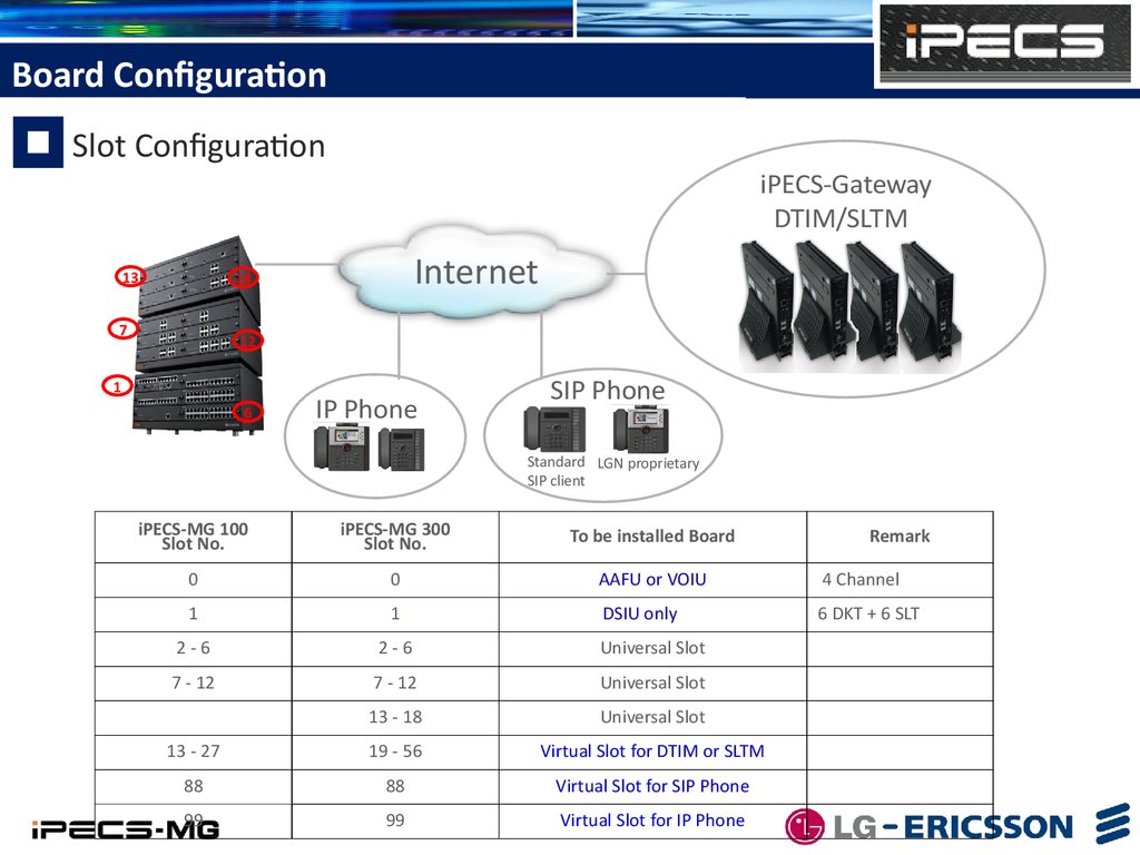
Board ConfigurationSlot Configuration
13
iPECS-Gateway
DTIM/SLTM
Internet
18
7
12
1
6
IP Phone
SIP Phone
Standard LGN proprietary
SIP client
iPECS-MG 100
Slot No.
iPECS-MG 300
Slot No.
To be installed Board
0
0
AAFU or VOIU
4 Channel
1
1
DSIU only
6 DKT + 6 SLT
2-6
2-6
Universal Slot
7 - 12
7 - 12
Universal Slot
13 - 18
Universal Slot
13 - 27
19 - 56
Virtual Slot for DTIM or SLTM
88
88
Virtual Slot for SIP Phone
99
99
Virtual Slot for IP Phone
Remark
5.
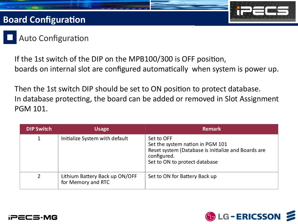
Board ConfigurationAuto Configuration
If the 1st switch of the DIP on the MPB100/300 is OFF position,
boards on internal slot are configured automatically when system is power up.
Then the 1st switch DIP should be set to ON position to protect database.
In database protecting, the board can be added or removed in Slot Assignment
PGM 101.
DIP Switch
Usage
Remark
1
Initialize System with default
Set to OFF
Set the system nation in PGM 101
Reset system (Database is initialize and Boards are
configured.
Set to ON to protect database
2
Lithium Battery Back up ON/OFF
for Memory and RTC
Set to ON for Battery Back up
6.
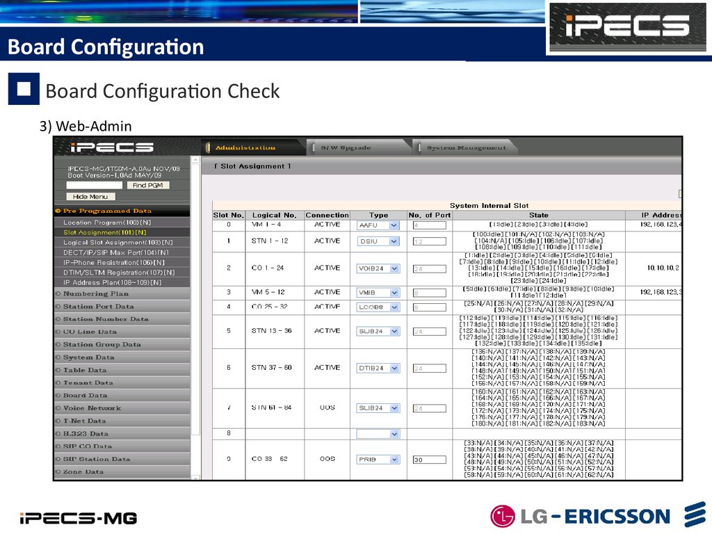
Board ConfigurationBoard Configuration Check
User can check board configuration through RS232, telnet or Web-Admin.
1) RS232
- Connect Serial Cable between PC
and Com Port on MPB.
- Set Baud Rate 115200.
- Enter maintenance Mode
- bs or bc
2) Telnet
- Connect with IP-Addr & 5003 port
(Default System IP = 10.10.10.1
It can be assigned in PGM 108)
- Enter maintenance password
(Can be assigned in PGM 226/Btn 3)
7.
Board ConfigurationBoard Configuration Check
3) Web-Admin
8.
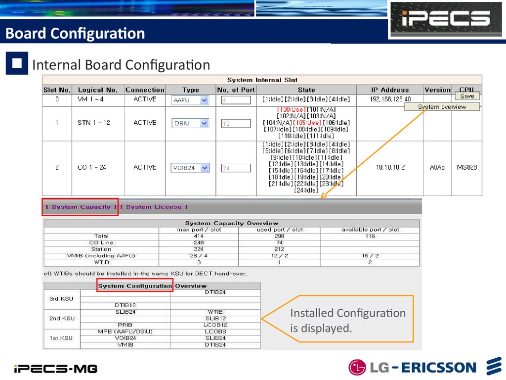
Board ConfigurationInternal Board Configuration
Installed Configuration
is displayed.
9.
Board ConfigurationIPECS-MG Gateway Configuration
IP Phone/SIP Phone Configuration
Add MAC Address to DTIM/SLTM Registration
Table (PGM 107), Then if GW tries to register. It
is registered without system reset.
10.
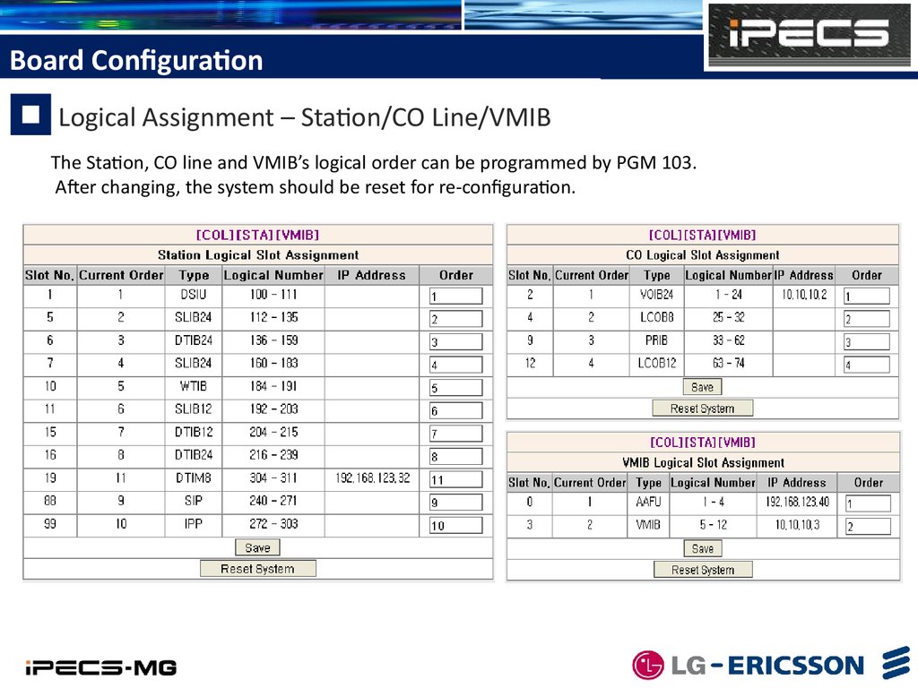
Board ConfigurationLogical Assignment – Station/CO Line/VMIB
The Station, CO line and VMIB’s logical order can be programmed by PGM 103.
After changing, the system should be reset for re-configuration.
11.
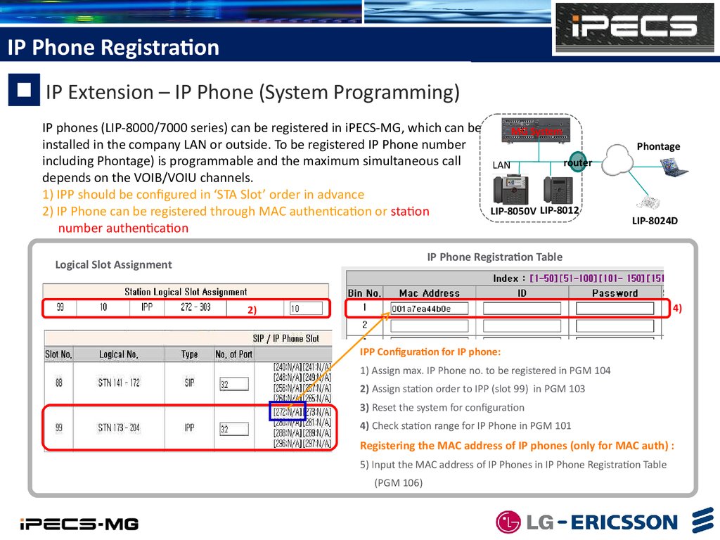
IP Phone RegistrationIP Extension – IP Phone (System Programming)
IP phones (LIP-8000/7000 series) can be registered in iPECS-MG, which can be
installed in the company LAN or outside. To be registered IP Phone number
including Phontage) is programmable and the maximum simultaneous call
depends on the VOIB/VOIU channels.
1) IPP should be configured in ‘STA Slot’ order in advance
2) IP Phone can be registered through MAC authentication or station
number authentication
MG System
Phontage
LAN
router
LIP-8050V LIP-8012
LIP-8024D
IP Phone Registration Table
Logical Slot Assignment
4)
2)
IPP Configuration for IP phone:
1) Assign max. IP Phone no. to be registered in PGM 104
2) Assign station order to IPP (slot 99) in PGM 103
3) Reset the system for configuration
4) Check station range for IP Phone in PGM 101
Registering the MAC address of IP phones (only for MAC auth) :
5) Input the MAC address of IP Phones in IP Phone Registration Table
(PGM 106)
12.
IP Phone RegistrationIP Extension – IP Phone Configuration
IP Phone should be programmed on the phone.
1)Install the IP Phone and Cabling
2)Setting the Mode as Remote (iPECS-MG only supports remote mode.)
3)Setting the IP address of system (MPB)
4)Setting the IP address of IP Phone : At home => DHCP mode , at company => Fixed or DHCP
5)Setting the INPUT DEVICE NUMBER(only for STA number auth) : this is the STA number of iPECS-MG system
6)Rebooting. IP Phone tries to connect to the system and connected.
NO RESPONSE FROM MFIM[L]
SET[*] - RETRY[#]
MODE[R/L]
[REMOTE] - CHANGE[#]
2
MFIM IP ADDRESS(DOT:*)
192.168.123.40
3
4-a
DHCP ?
[DISABLED]
1
CHANGE[#}
4-b
2) The following message will be shown. Leave the
mode as “Remote” as default set. Move the menu
to the next by using Volume up/down button.
To change (Toggle) the value press “#”.
PHONE NET MASK(DOT:*)
255.255.255.0
3) Input the IP Address of system (MPB).
Press “Hold/Save” button to save. Press “Speaker
ROUTER IP ADDRESS(DOT:*)
150.150.131.254
4-a/b) Set DHCP enabled or input fixed IP address for
the IP phone. In general, DHCP mode at home
and Fixed IP mode at office.
5) Enter station number to be assigned if STA number
registration. Station number allocated for IPP should
be entered.
6) Upon completion, press “Hold/Save” then press
“Speaker. It will be rebooting to get connected to
the system.
PHONE IP ADDRESS(DOT:*)
150.150.131.166
INPUT DEVICE NUMBER
273
REBOOTING…
AFTER SETTING
1) Power on the IP Phone. the following message will
be displayed on LCD. Press”*” to enter the setup.
If password requested, press “1 4 7 *” by default.
5
6
13.
IP Phone RegistrationIP Phone Voice Connection
When IP phone talks to Digital Phone or accesses CO line,
The voice is connected to the associate device through VOIB.
VOIB Channel is allocated to IP Phone from his Zone’s VOIB Resource.
The signaling between system and IP/SIP phone is communicated through MPB IP Address.
But the RTP is communicated through VOIB.
This rule is applied to SIP voice connection.
IP Phone/SIP Phone’s Zone
Zone Attribute
MPB
VOIB
router
LAN
LIP-8050V
RTP
Signaling
14.
SIP Phone RegistrationSIP Extension - SIP Phone (System Programming)
Standard SIP phones can be registered in iPECS-MG, which can be installed in
the company LAN or outside. To be registered SIP Phone is programmable
and the maximum simultaneous call depends on the VOIB/VOIU channels.
1) SIP should be configured in ‘STA Slot’ order in advance
2) SIP Phone can be registered through ID & Authentication ID
& Password authentication
MPB
VOIB
MG System
LAN
Standard
SIP client
Standard
SIP client
router
LGN
proprietary
LGN proprietary
SIP Station Basic Registration Table
Logical Slot Assignment
2)
4)
SIP Configuration for IP phone:
1) Assign max. SIP Phone no to be registered in PGM 104.
2) Assign station order to IPP (slot 88) in PGM 103
3)
3) Reset the system for configuration
Check station range for SIP Phone in PGM 101 after system booting
4) Input the ID/Auth/PSWD of SIP phones in SIP Station Basic
Registration Table. (Web Admin, SIP STA Base Registration)
15.
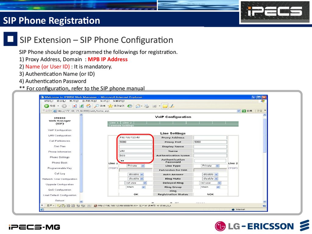
SIP Phone RegistrationSIP Extension – SIP Phone Configuration
SIP Phone should be programmed the followings for registration.
1) Proxy Address, Domain : MPB IP Address
2) Name (or User ID) : It is mandatory.
3) Authentication Name (or ID)
4) Authentication Password
** For configuration, refer to the SIP phone manual
16.
MPB Software UpgradeS/W Upgrade – Web-Admin
System Software can be upgraded through Web-Admin
1)
1) Select [S/W Upgrade]
2) Click File Upload
3) Select ‘S/W File’ to upgrade
2)
3)
4)
4) Click [Upload]
If file upload succeeds,
a success page will be displayed.
5) Reset the system
Then uploaded s/w is applied.
17.
MPB Software UpgradeS/W Upgrade – USB
The Attendant can upgrade system through USB memory.
Before upgrading, a user have to save system Rom file
(GS55(56)MXXXX.rom) in USB memory
To upgrade from Attendant;
1) Save system Rom file (GS55(56)MXXXX.rom) in USB memory
2) Insert the USB memory to the USB port in MPB board.
3) Press the [PGM] button and Dial ‘091’, the Attendant Station Program code.
MOUNT USB MEMORY
PLEASE WAIT…
5) Number of system Rom file in USB memory is displayed.
ROM FILE NUM : TOTAL 2
PRESS 0-1 TO VIEW FILE
6) Dial Number of system Rom file to display system Rom file name.
0: GS56MA0Aa.rom
PRESS HOLD TO UPGRADE
7) Press the [HOLD] button to upgrade system.
8) After some minutes, result of upgrade is displayed and Keyset goes to IDLE state.
SOFTWARE UPGRADE
USB UPGRADE SUCCESS
9) Restart the System.
USB
18.
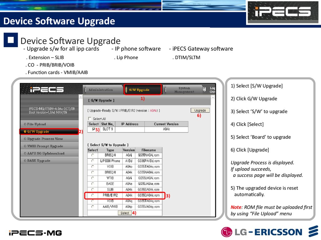
Device Software UpgradeDevice Software Upgrade
- Upgrade s/w for all ipp cards
. Extension – SLIB
. CO - PRIB/BRIB/VOIB
. Function cards - VMIB/AAIB
- IP phone software
- iPECS Gateway software
. Lip Phone
. DTIM/SLTM
1) Select [S/W Upgrade]
2) Click G/W Upgrade
1)
6)
2)
3) Select ‘S/W’ to upgrade
4) Click [Select]
5)
5) Select ‘Board’ to upgrade
6) Click [Upgrade]
Upgrade Process is displayed.
If upload succeeds,
a success page will be displayed.
3)
4)
5) The upgraded device is reset
automatically.
Note: ROM file must be uploaded first
by using “File Upload” menu
19.
VM Prompt UpgradePrompt Upgrade – VMIB/AAIB/AAFU
- All Language Prompts are uploaded to MPB when MPB is produced from factory.
- 1 VM board supports 3 Languages.
- Language selection is programmable per station & CO line Base
1) Select [S/W Upgrade]
1)
7)
3) Select ‘Prompt’ to upload
6)
2)
2) Click VMIB Prompt Upgrade
5)
4) Click [Select]
5) Select ‘Board’ to upgrade
& Prompt Index
6) Click [Upgrade]
Upgrade Process is displayed.
If upload succeeds,
a success page will be displayed.
3)
4)
20.
System Greeting Upload/DownloadSystem Greeting Upload/Download
- VM System Greeting can be recorded by [Sound Recorder]
- Each S/G can be uploaded or downloaded
- Recorded S/Gs can be downloaded as one merged file
- One merged S/G file can be uploaded to another VMIB/AAIB/AAFU
- AAFU : Up&Download through Web-Admin
- VMIB/AAIB : Up&Download through board Web
21.
VM System Greeting Upload/DownloadSystem Greeting (Individual) – AAFU
1) Each S/G can be uploaded with wav file format
1)
If a user want to upload
to type #3 System greeting 25,
1. Select “Third”
2. Upload file name should be
25.wav or 3_25.wav
2)
• Wave File Format : CCITT A-Law, 8000KHz, 8 bit, Mono)
2) Each S/G can be downloaded as wav file format
If a user click 1.wav,
file name is 1_1.wav.
(1 means type #1)
22.
VM System Greeting Upload/DownloadSystem Greeting (All) – AAFU
1) ) S/Gs can be uploaded as one merged file
1)
2)
If a user want to upload
to type #3 whole System
greeting,
1. Select “Third”
2. Upload file name
should be
SGTYPE1.rom
SGTYPE2.rom
SGTYPE3.rom
2) Recorded S/Gs can be downloaded as one merged file
File name :
SGTYPE1.rom,
SGTYPE2.rom,
SGTYPE3.rom
example)
1.wav, 21.wav, 71.wav
=> SGTYPE1.rom
23.
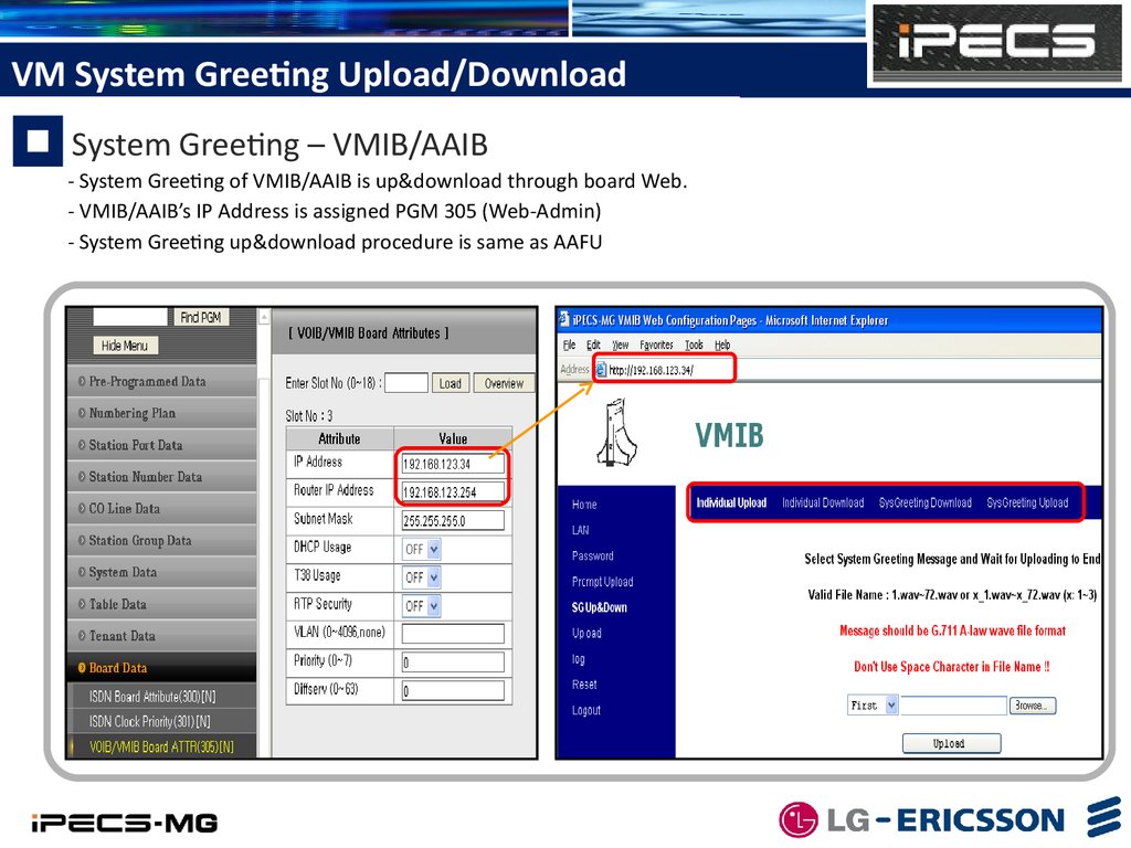
VM System Greeting Upload/DownloadSystem Greeting – VMIB/AAIB
- System Greeting of VMIB/AAIB is up&download through board Web.
- VMIB/AAIB’s IP Address is assigned PGM 305 (Web-Admin)
- System Greeting up&download procedure is same as AAFU