


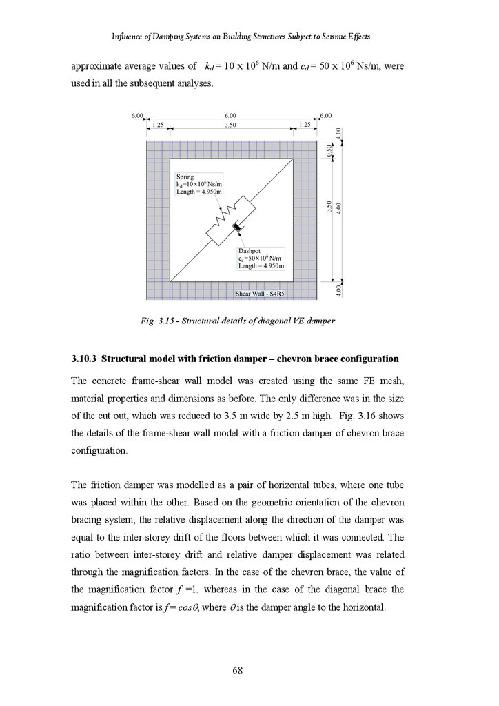
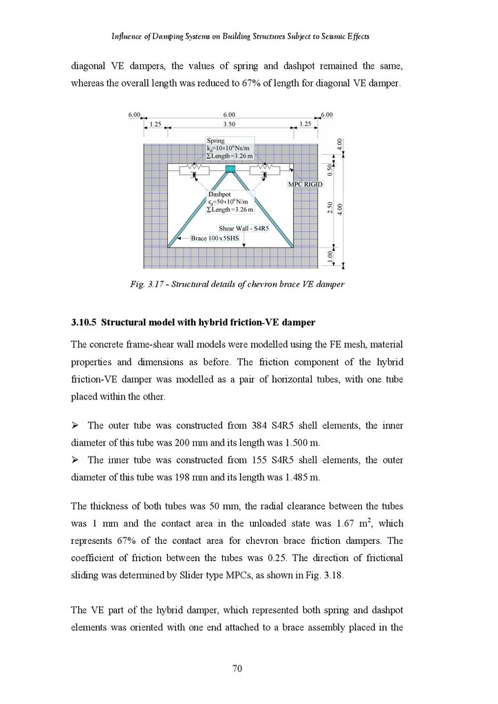
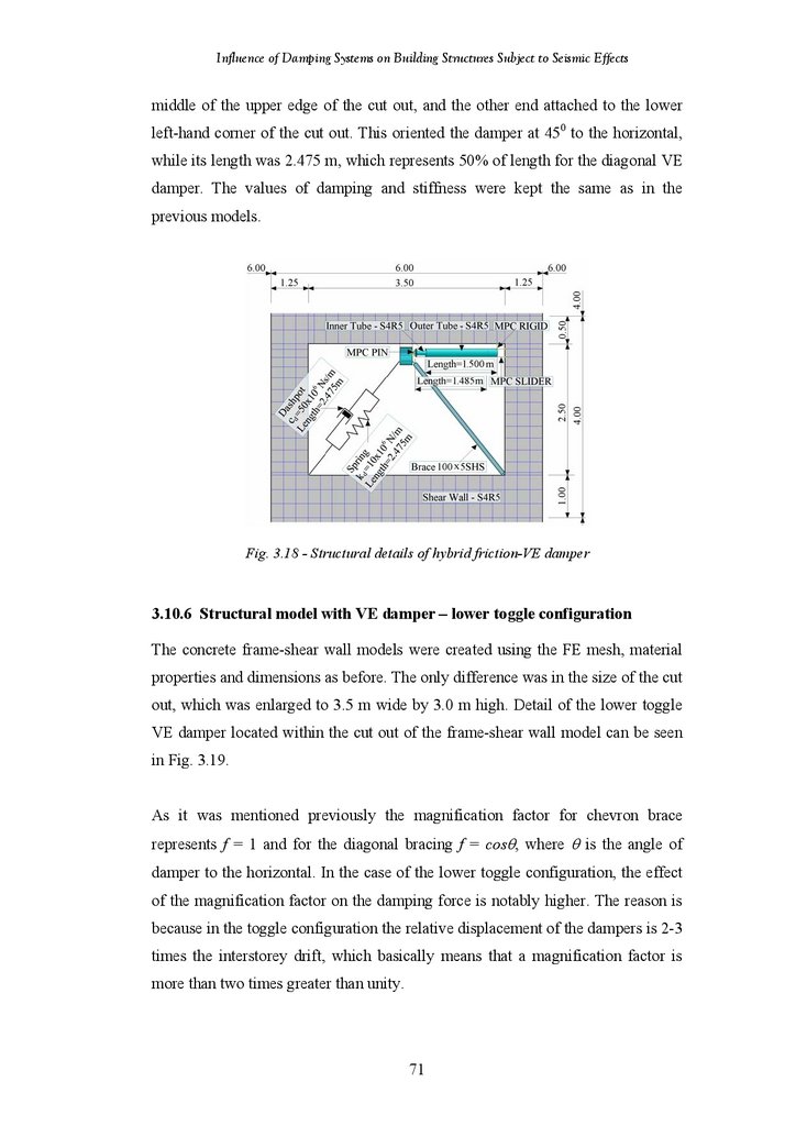


 Строительство
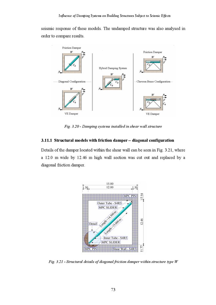
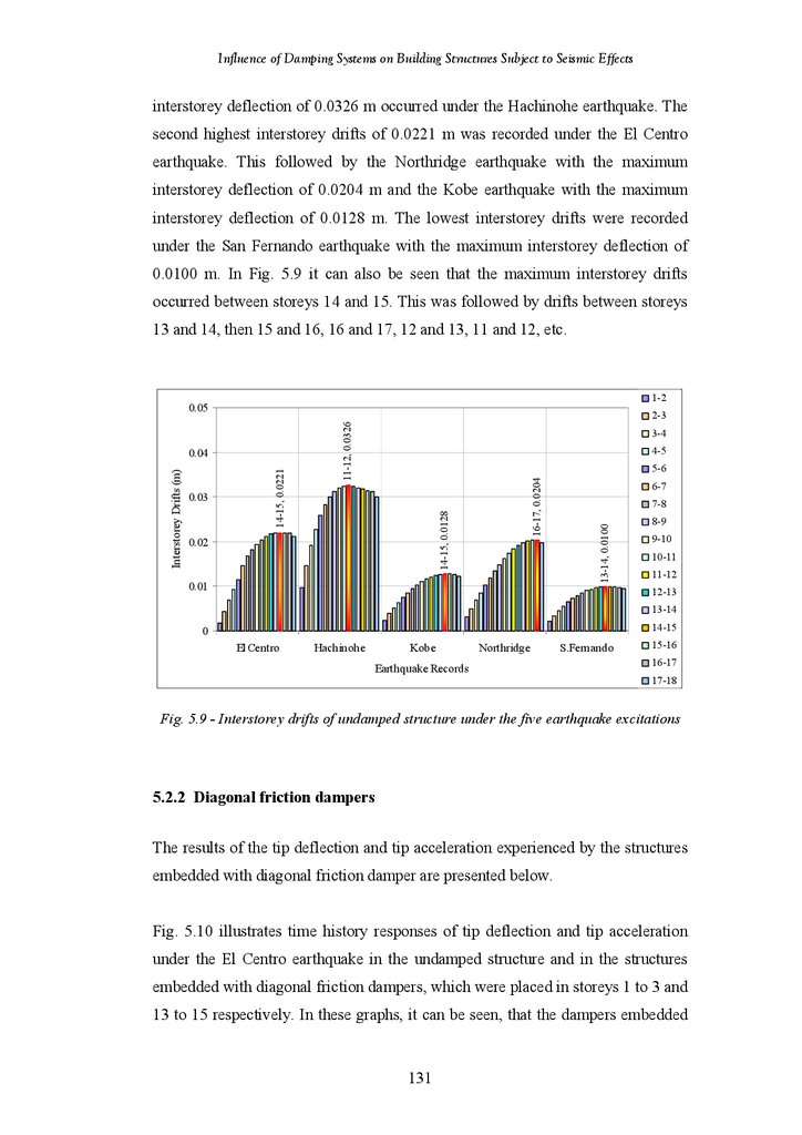
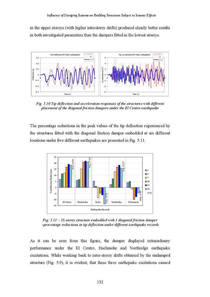
Похожие презентации:
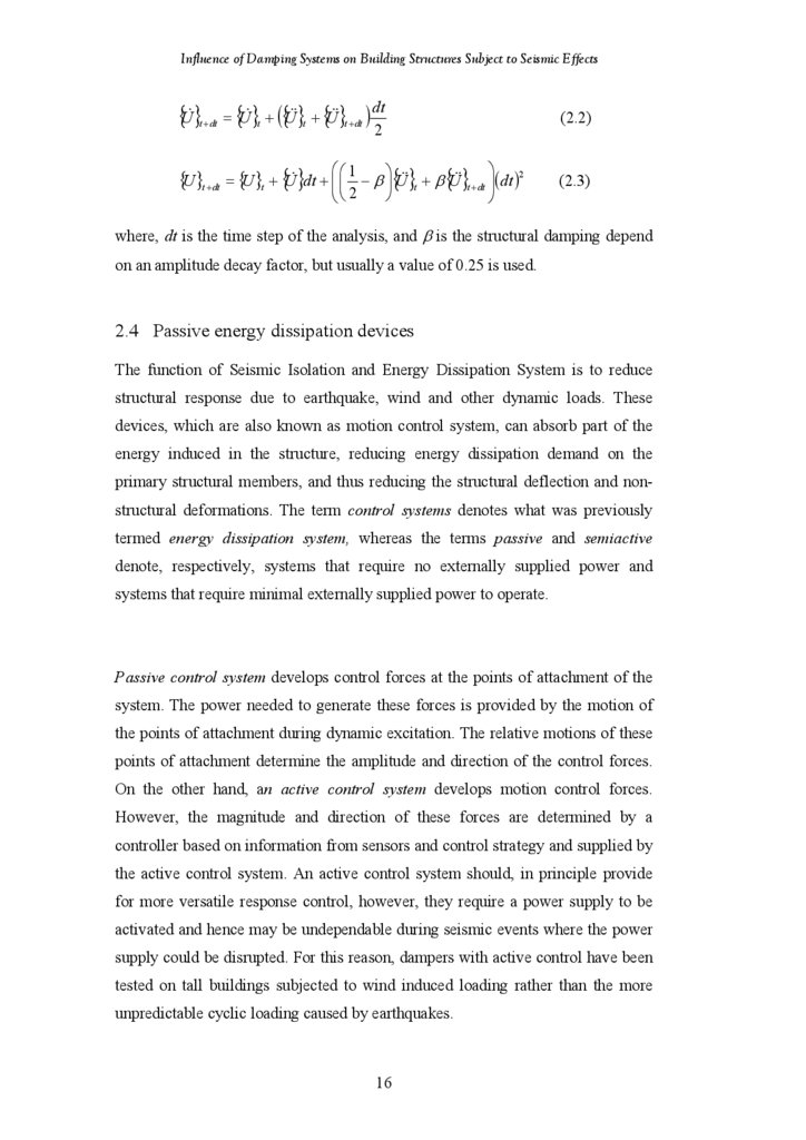
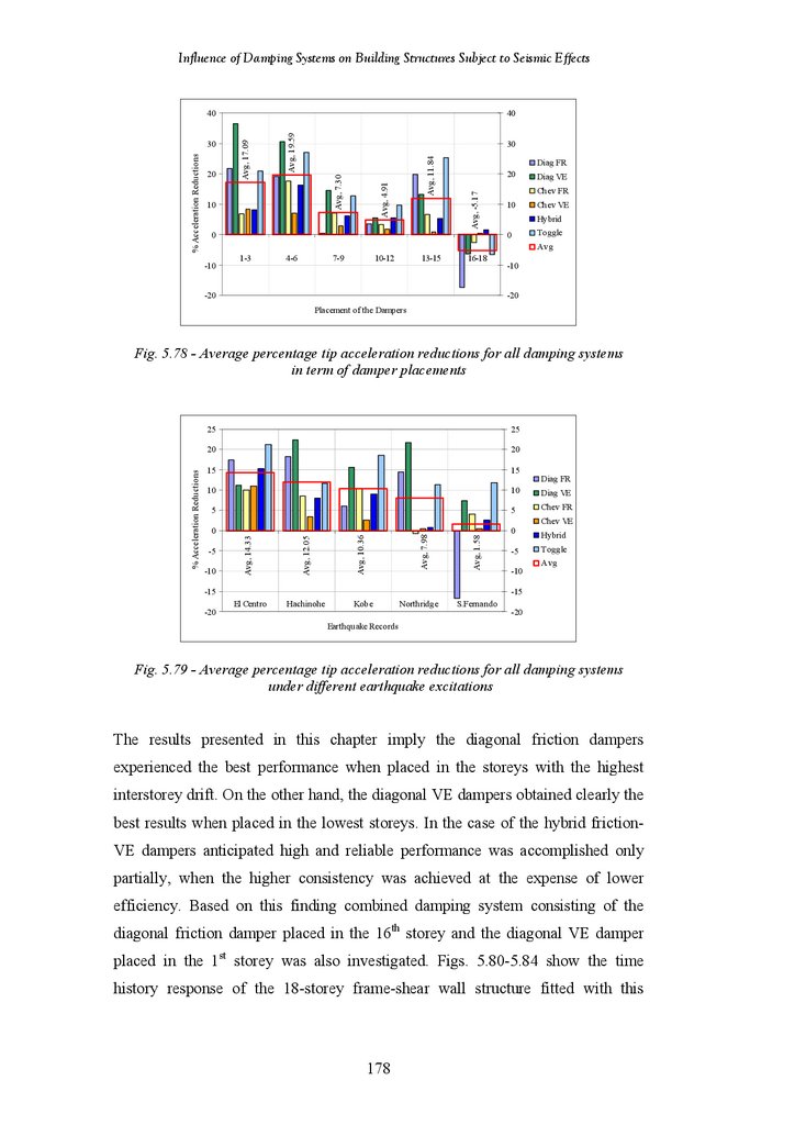
")


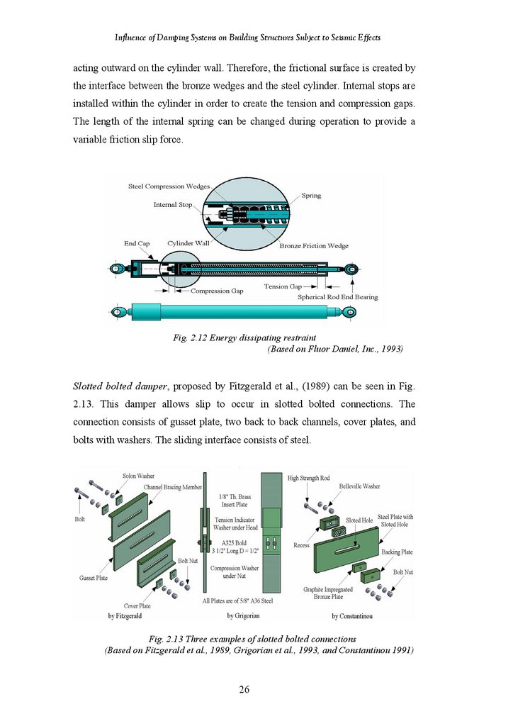
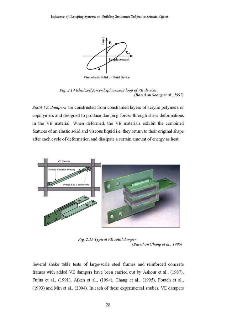
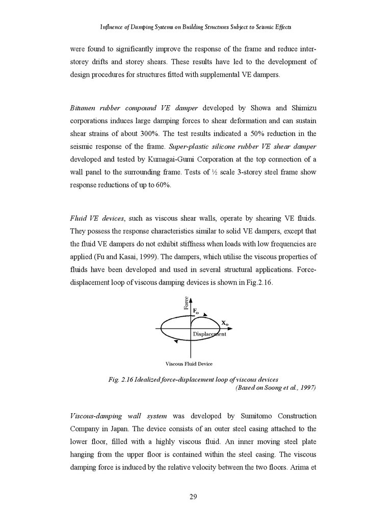
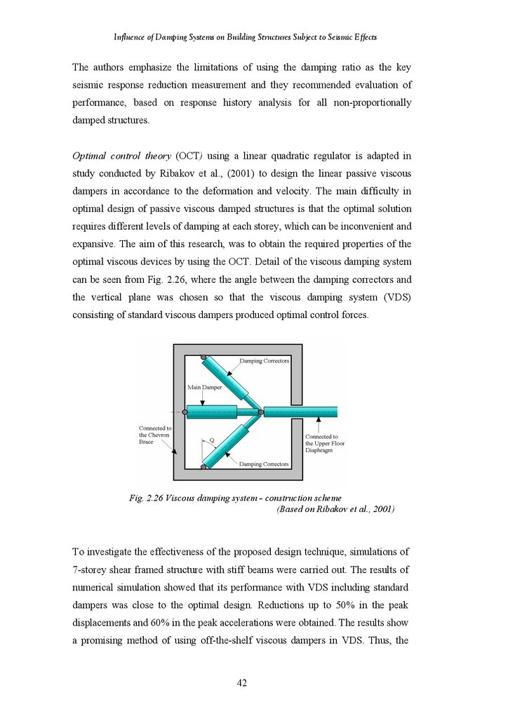
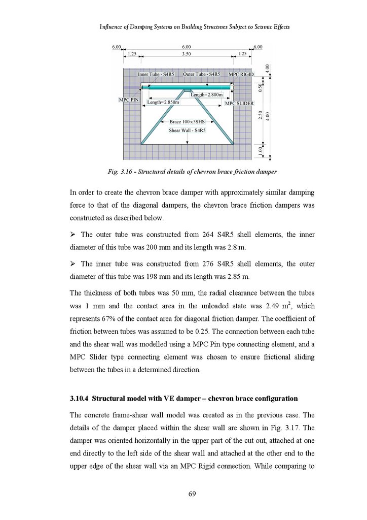
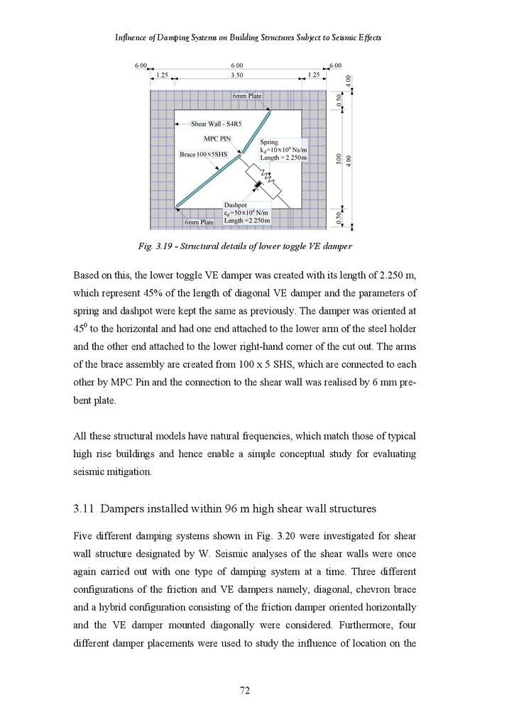
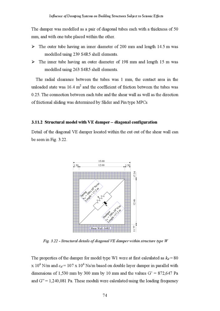
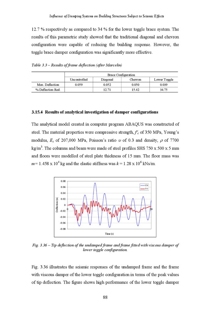
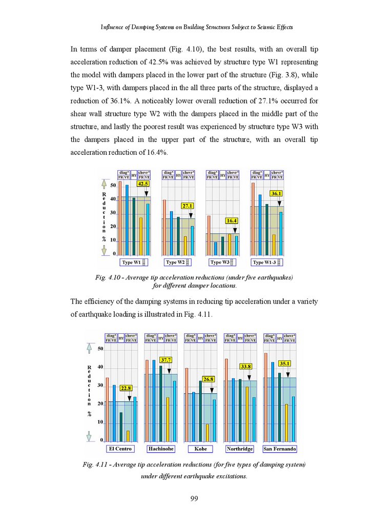
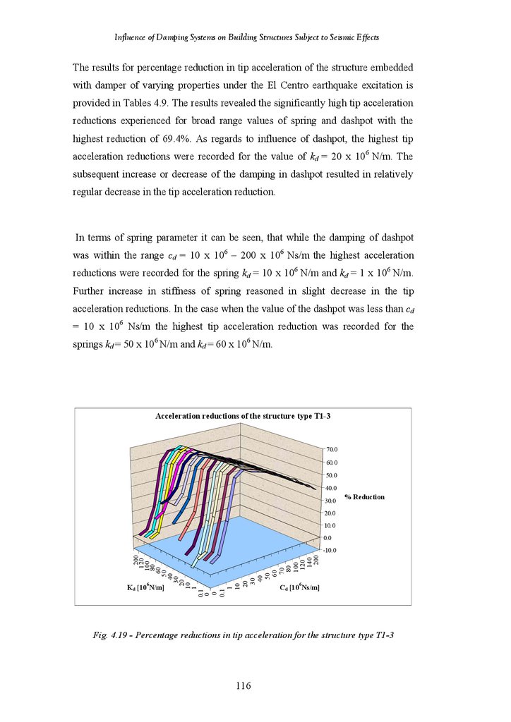
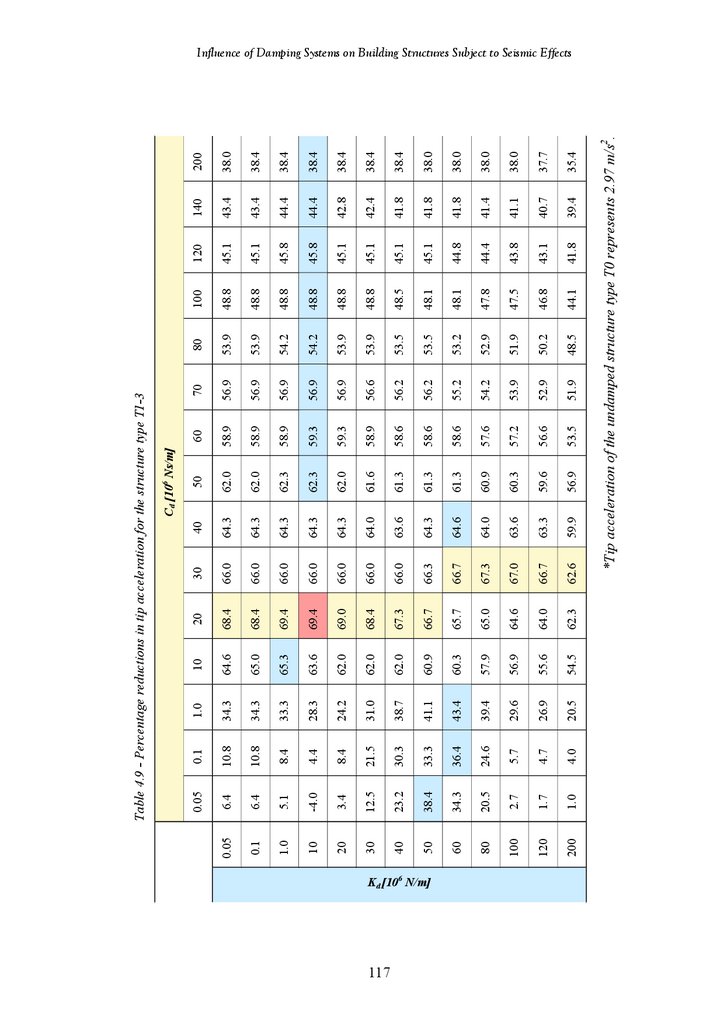
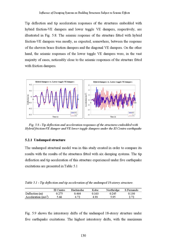
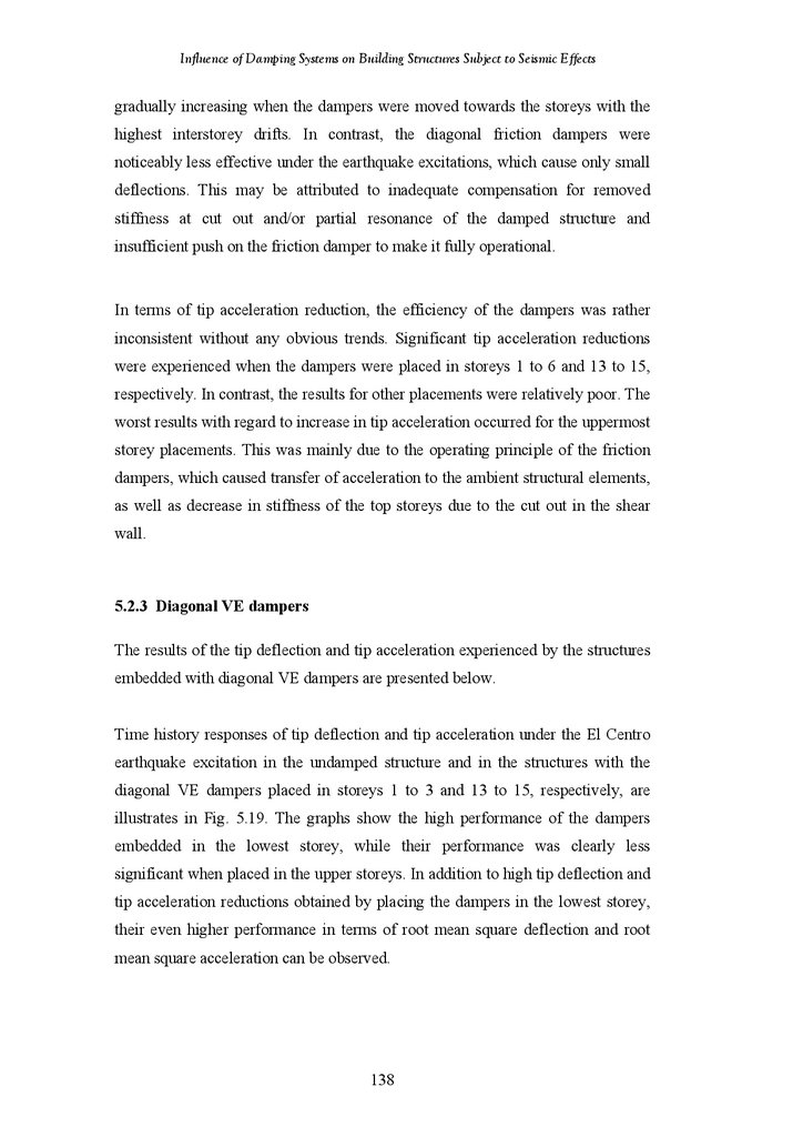
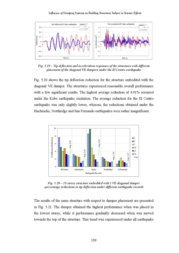
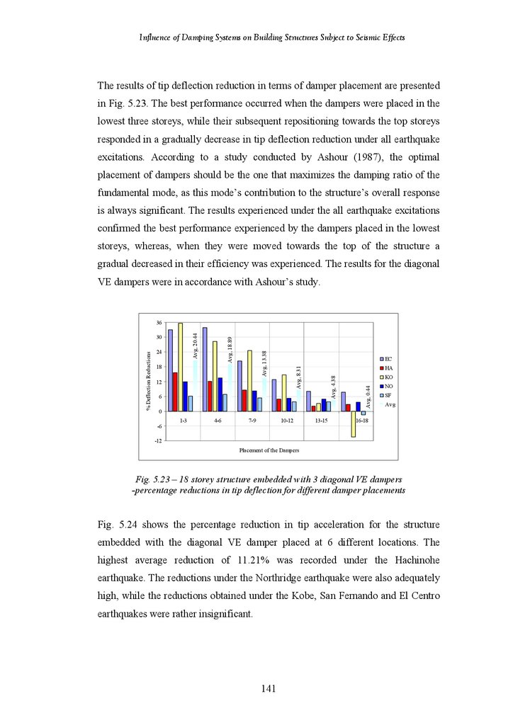
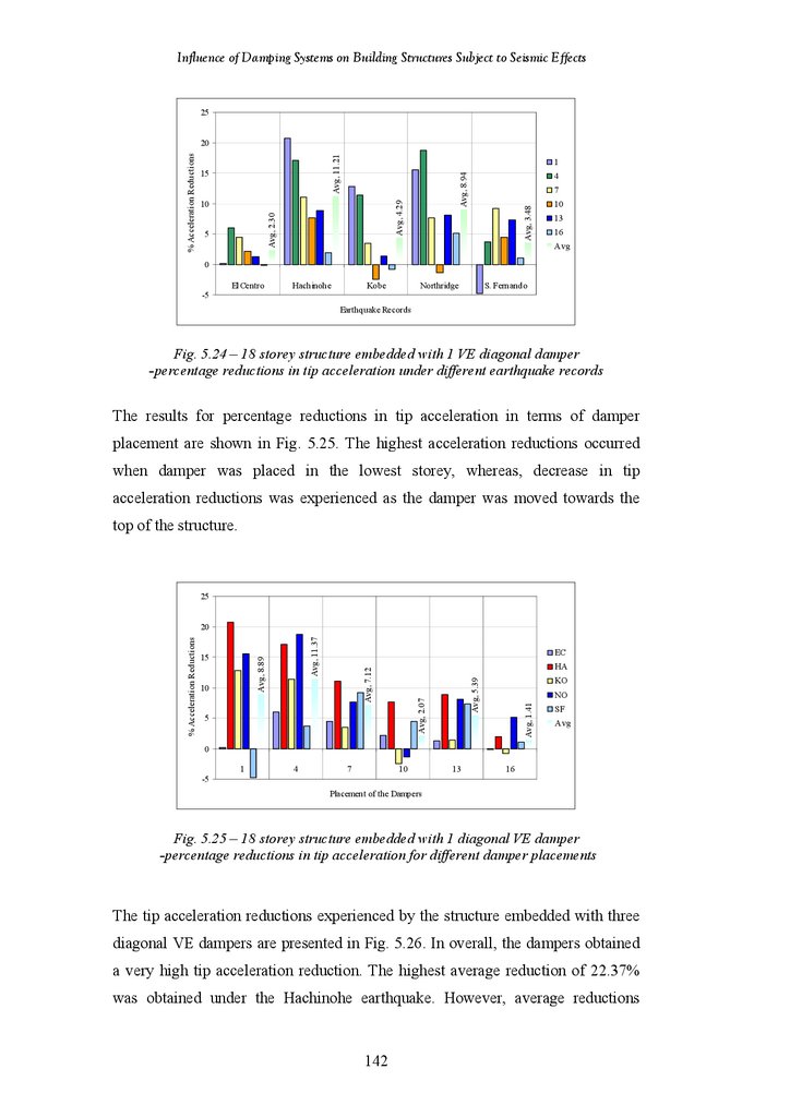
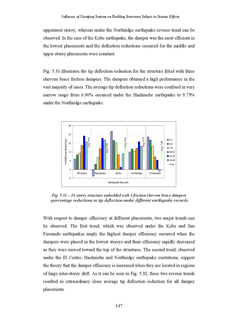
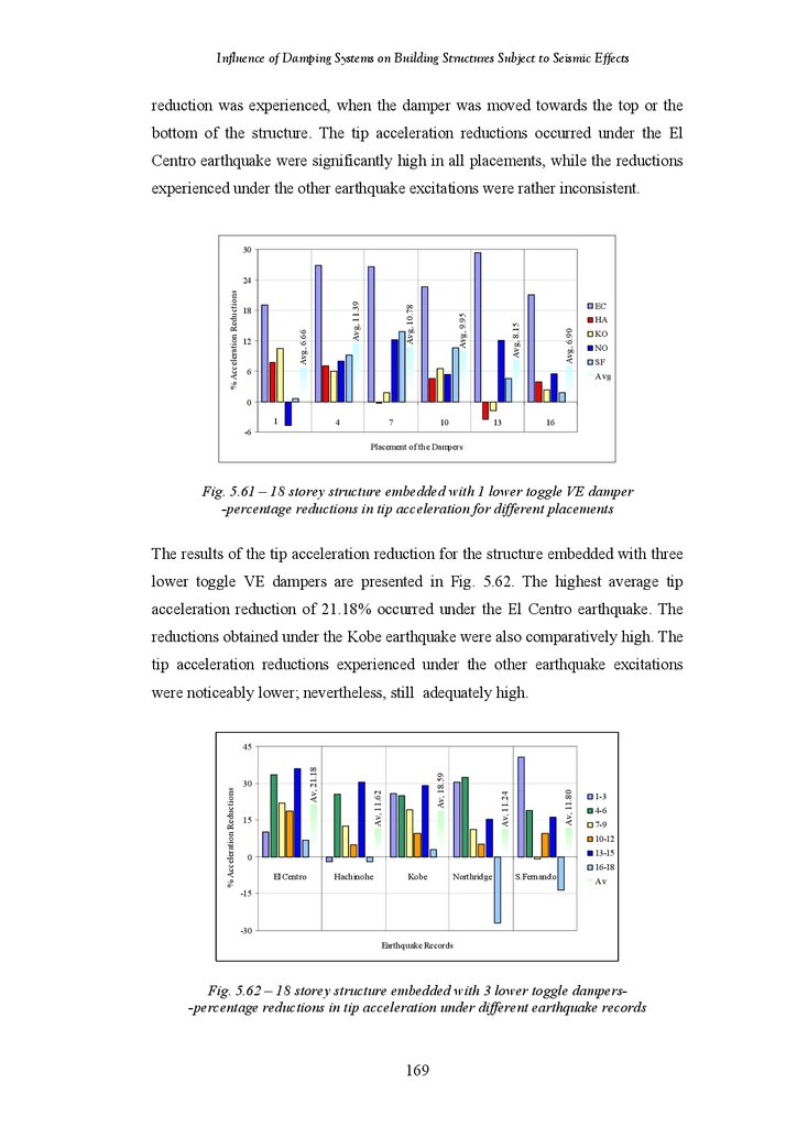
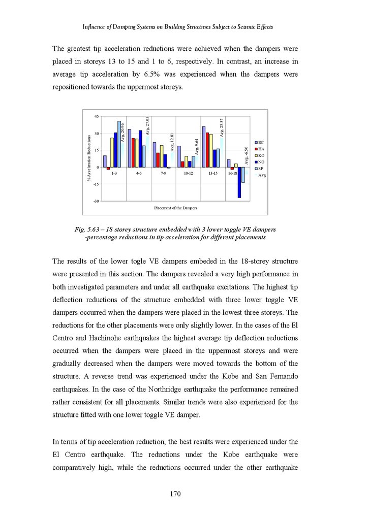
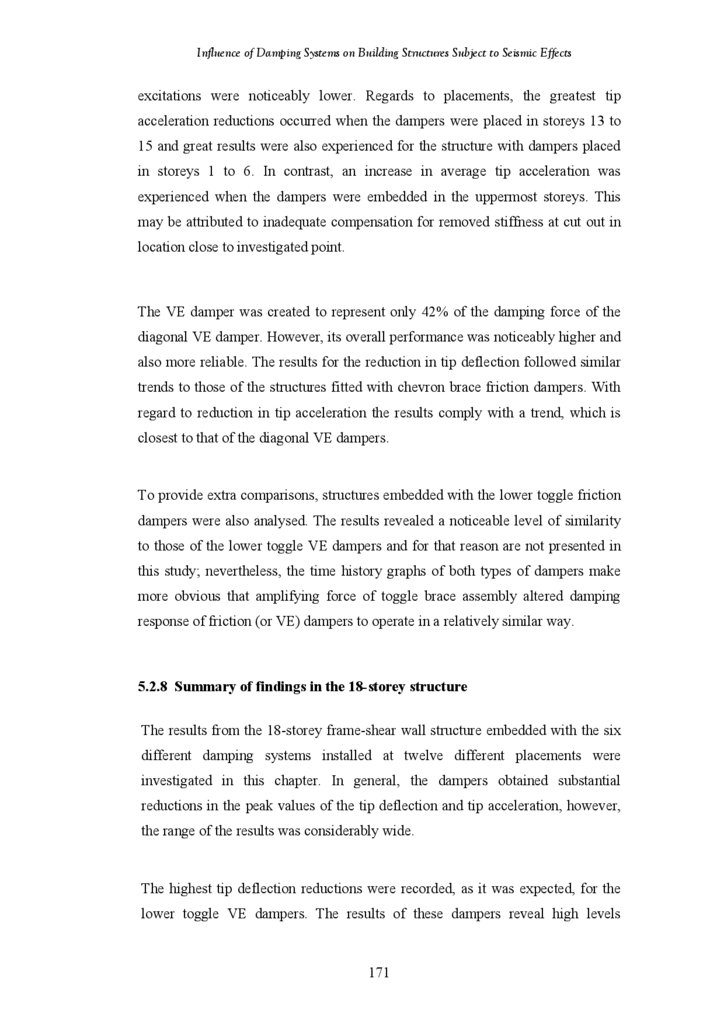
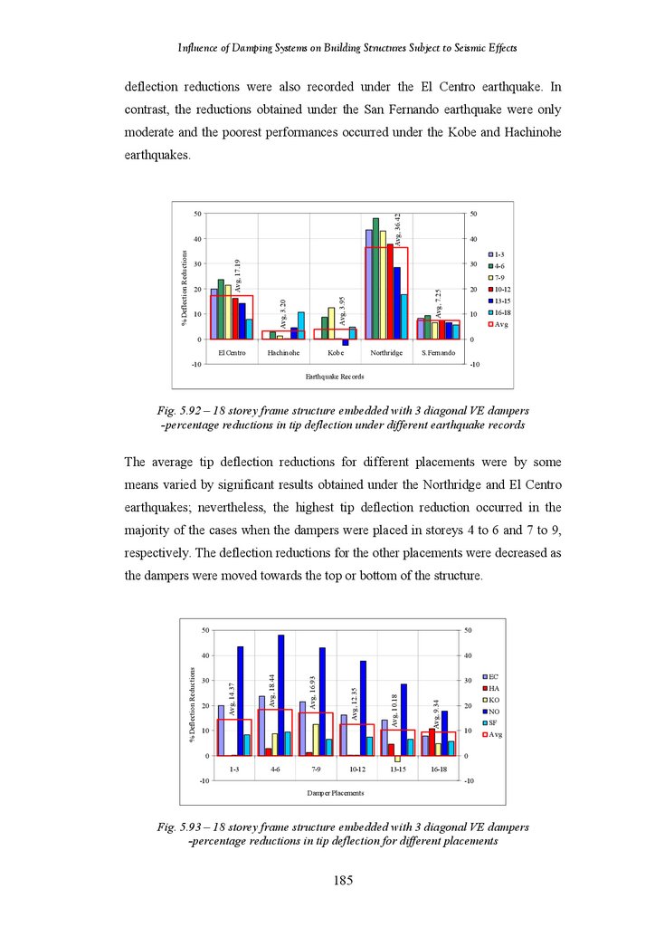
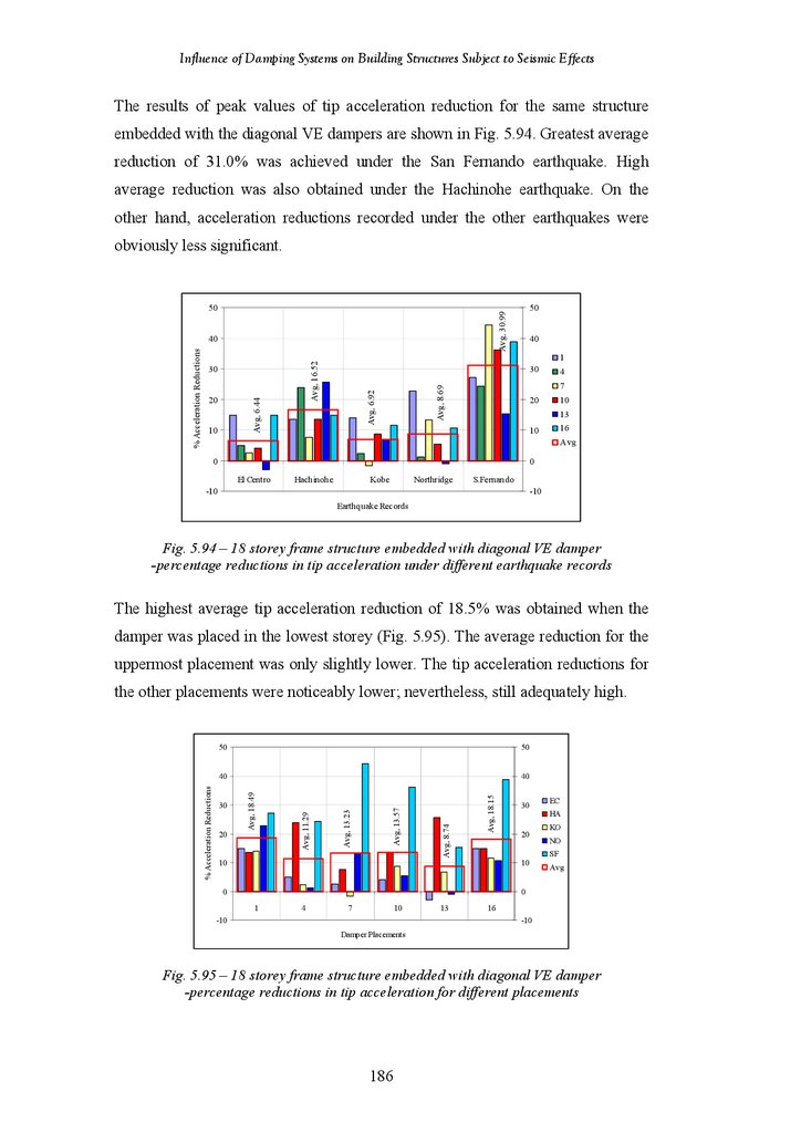
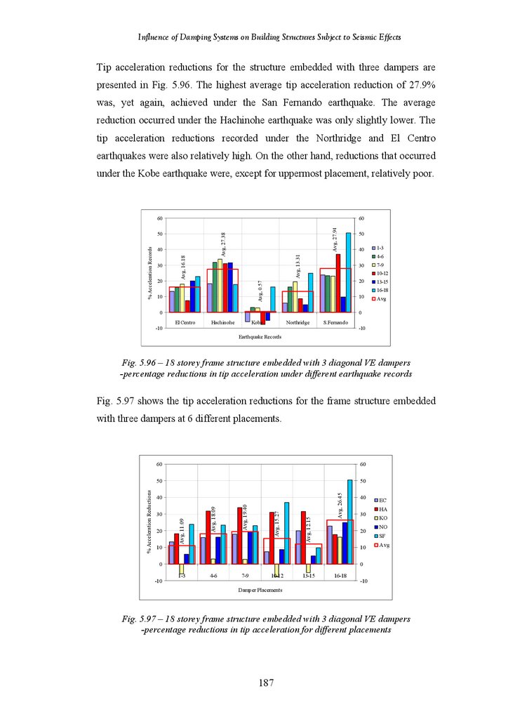
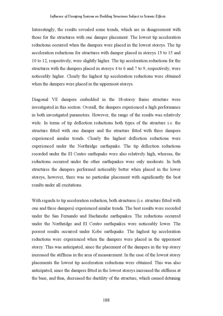
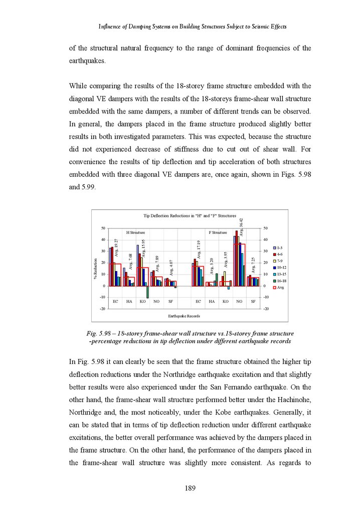
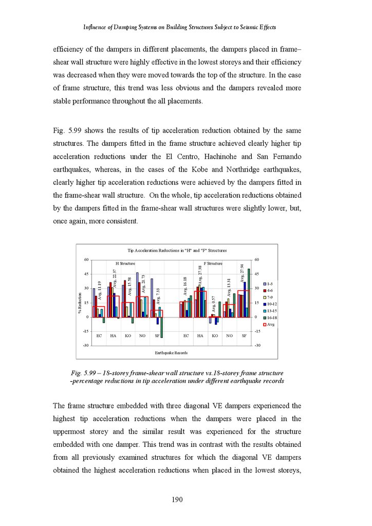
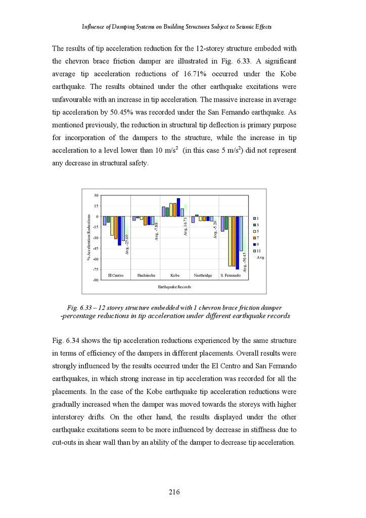
Influence of Damping Systems
1.
Influence of Damping SystemsOn Building Structures
Subject to Seismic Effects
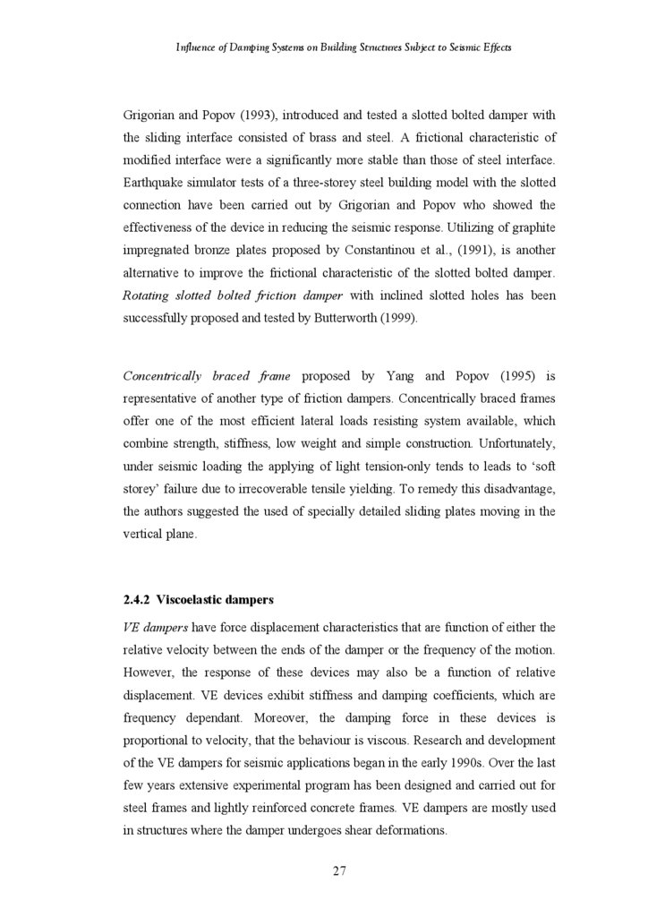
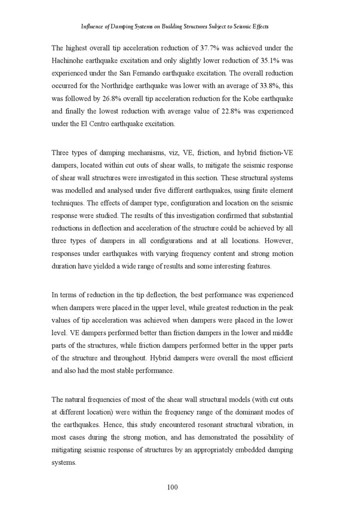
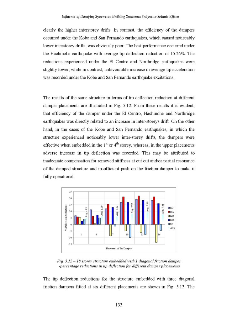
Julius Marko
May 2006
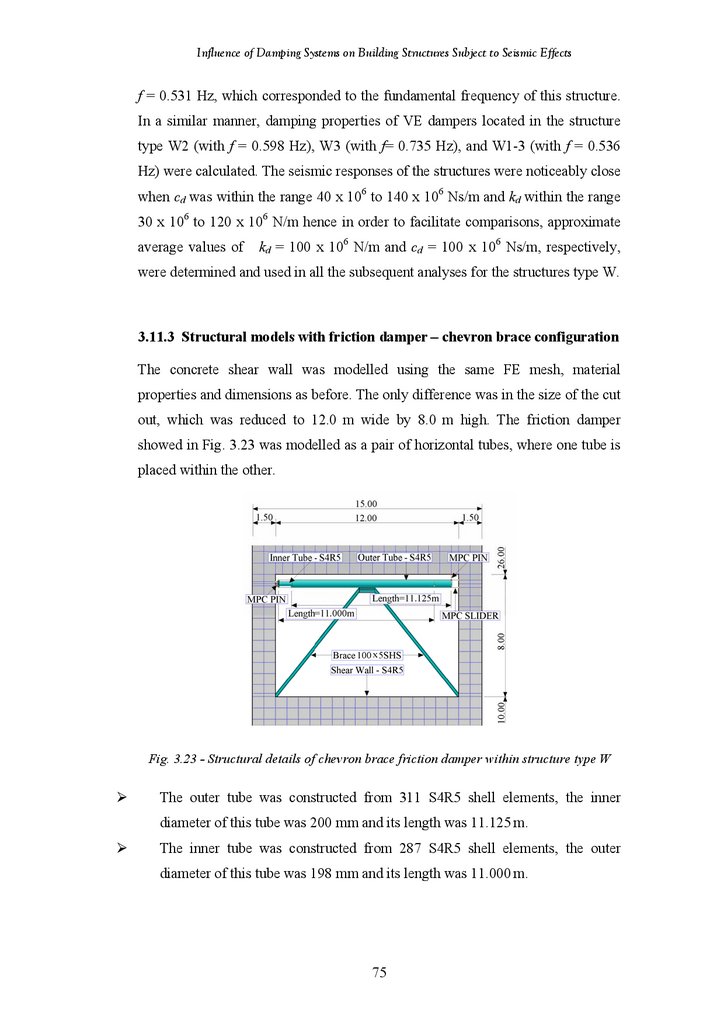
2.
ii3.
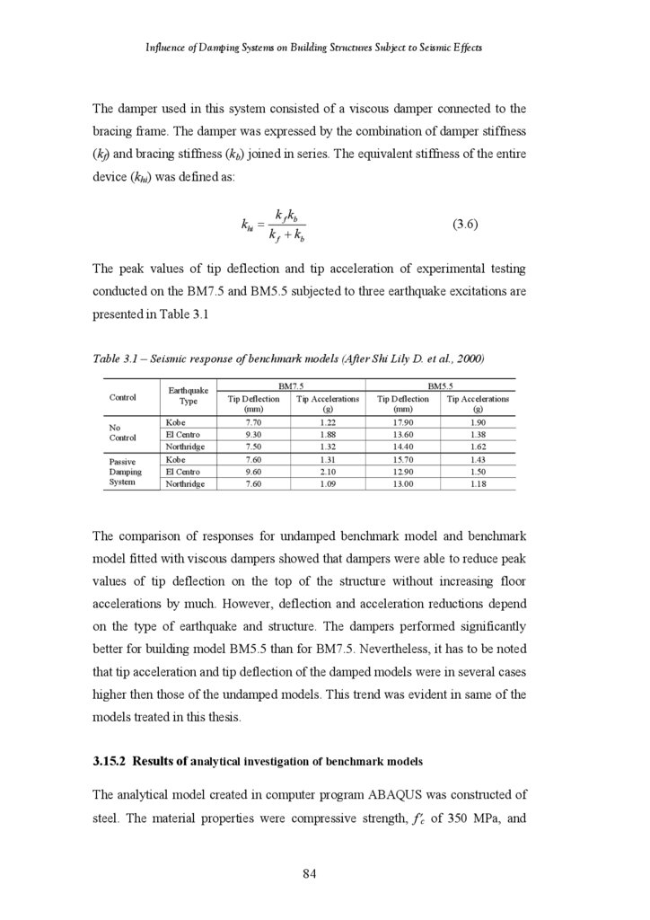
AbstractIn order to control the vibration response of high rise buildings during seismic
events, energy absorbing passive damping devices are most commonly used for
energy absorption. Today there are a number of types of manufactured dampers
available in the market, which use a variety of materials and designs to obtain
various levels of stiffness and damping. Some of these include friction, yielding,
viscoelastic and viscous dampers. These dampers are usually installed between
two load bearing elements (walls or columns) in new buildings. In existing
buildings, which require retrofitting, they could be installed in cut-outs of shear
walls, as evidenced from recent investigations. An effective damping system can
result in higher levels of safety and comfort, and can also lead to considerable
savings in the total cost of a building.
This thesis treats seismic mitigation of multistorey buildings using embedded
dampers. Three types of damping mechanisms, viz, friction, viscoelastic, and
combined friction-viscoelastic were investigated. Finite element methods were
employed in the analysis using the program ABAQUS version 6.3. A direct
integration dynamic analysis was carried out to obtain the damped and undamped
responses of the structure in terms of deflections and accelerations at all storeys in
order to evaluate the effectiveness of the damping system in mitigating the
seismic response. The damping mechanisms have been modelled as (i) a linear
spring and dash-pot in parallel for the viscoelastic damper, (ii) a contact pair with
friction parameter for a friction damper and (iii) a hybrid damper consisting of
both a viscoelastic and a friction damper. The earthquake events used in this study
have been applied as acceleration time-histories at the base of the structure in the
horizontal plane. Concrete material properties were chosen to represent the model
as many high-rise buildings are constructed by using reinforced concrete.
Several medium and high-rise building structures with embedded dampers in
different configurations and placed in various locations throughout the structure
were subjected to different earthquake loadings. Influence of damper type and
properties, configuration and location were investigated. Results for the reduction
in tip deflection and acceleration for a number of cases demonstrate the feasibility
of the technique for seismic mitigation of these structures for a range of
excitations, even when the dominant seismic frequencies match the natural
frequency of the structure. Results also provide information which can be used for
optimal damper placement for seismic mitigation.
Keywords
Seismic response; Friction damper; Viscoelastic damper; Damping; Configuration
i
4.
Influence of Damping Systems on Building Structures Subject to Seismic EffectsPublications
International Refereed Journal Papers:
“Influence of Damping Systems on Building Structures Subject to Seismic
Effects” Journal of Engineering Structures 26, November 2004, 1939-1956.
“Mitigating Seismic Response of Shear Wall Structures Using Embedded
Dampers” Institution of the Structural Engineer (UK), January 2006.
“Study of Viscoelastic and Friction Damper Configurations in the Seismic
Mitigation of Medium-Rise Structures” Journal of Mechanics of Materials and
Structures, Accepted in April 2006 for Publication in 2006.
International Refereed Conference Papers:
“Influence of Damping Systems on Building Structures Subject to Seismic
Effects” Proceedings of the Ninth International Conference on Civil and
Structural
Engineering
Computing,
Egmond-aan-Zee,
The
Netherlands,
September 2003.
“Comparative Study on the Efficiency of Friction and Viscoelastic Dampers
within Shear Walls” Proceedings Second International Conference on Structural
Engineering Mechanics and Computations, Cope Town, South Africa, September
2004.
“Seismic Response of Building Structures Using Embedded Dampers” Australian
Earthquake Engineering in the New Millenium -Where to from Here?
Proceedings of the Conference, Mt. Gambier, South Australia, November 2004.
ii
5.
Influence of Damping Systems on Building Structures Subject to Seismic EffectsContents
Abstract
Keywords
Publications
Contents
List of Figures
List of Tables
Notations
Statement of Original Authorship
Acknowledgements
i
i
ii
iii
vi
xvii
xvii
xx
xxi
1.1
1.2
1.3
1.4
1.5
1.6
CHAPTER 1 INTRODUCTION
Background to the Study
Problem Researched
Aims and Objectives
Method of Investigation
Scope of Research
Layout of Thesis
1
2
5
6
6
7
8
2.1
2.2
2.3
2.3.1
2.3.2
2.4.
2.4.1
2.4.1.1
2.4.1.2
2.4.2
2.4.3
2.4.4
2.4.5
2.5
2.6
2.7
2.8
2.8.1
2.8.2
CHAPTER 2 LITERATURE REVIEW
Introduction
Seismic Design Concept
Analysis Procedures
Static Analysis Procedures
Dynamic Analysis Procedures
Passive Energy Dissipation Devices
Hysteretic Energy Dissipation Devices
Metallic Dampers
Friction Dampers
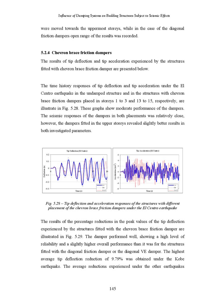
Viscoelastic Dampers
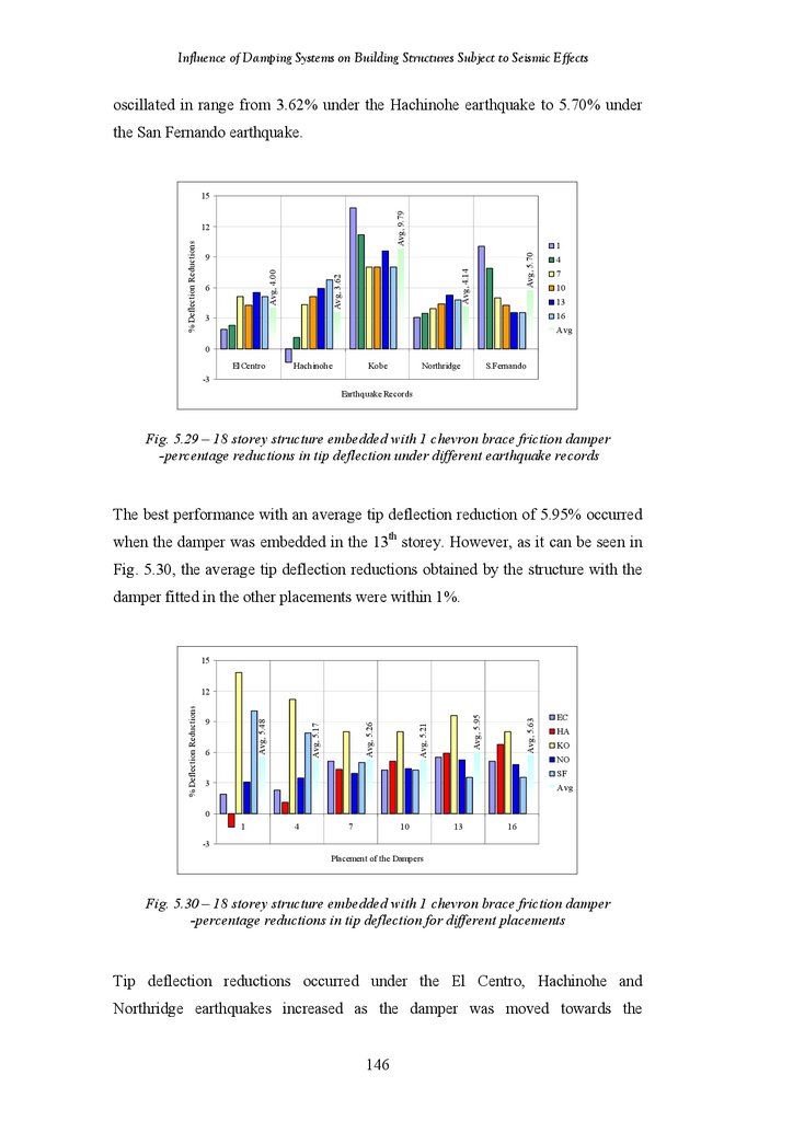
Dynamic Vibration Absorbers
Phase Transformation Dampers
Hybrid Dampers
Use of Energy Dissipation Devices in Building Structures
Research on Seismic Mitigation with Passive Dampers
Configurations of Energy Dissipation Devices
Conclusion to the Literature Review
Summary of the Literature Review
Proposed Research
10
11
12
15
15
15
17
19
20
24
28
33
36
37
38
44
49
54
54
54
3.1
3.2
3.3
3.3.1
CHAPTER 3 MODEL DEVELOPMENT & VERIFICATION
Introduction
Finite Element Modelling
Loading and Boundary Conditions
Boundary Conditions
56
57
58
58
58
iii
6.
Influence of Damping Systems on Building Structures Subject to Seismic Effects3.3.2
3.4
3.4.1
3.4.2
3.4.3
3.5
3.5.1
3.5.2
3.6
3.6.1
3.6.2
3.7
3.8
3.9
3.10
3.10.1
3.10.2
3.10.3
3.10.4
3.10.5
3.10.6
3.11
3.11.1
3.11.2
3.11.3
3.11.4
3.11.5
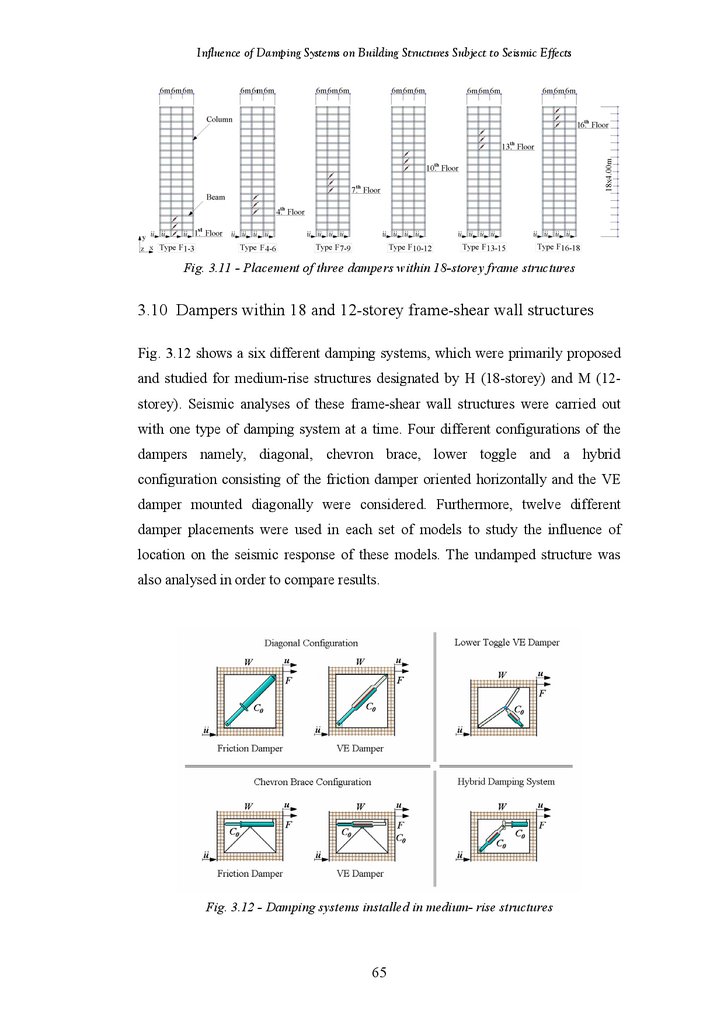
3.12
3.13
3.14
3.15
3.15.1
3.15.2
3.15.3
3.15.4
Material Properties
Damper Models
Friction Damper Model
Viscoelastic Damper Model
Hybrid Damper Model
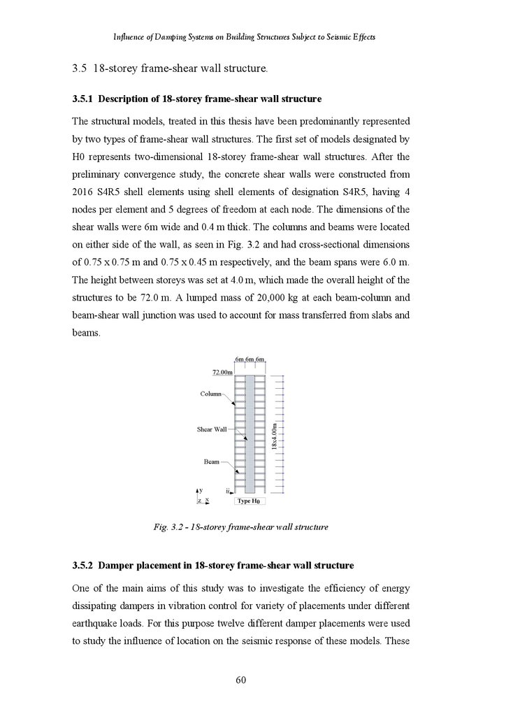
18-Storey Frame-Shear Wall Structure
Description of 18-Storey Frame-Shear Wall Structure
Damper Placement in 18-Storey Frame-Shear Wall Structure
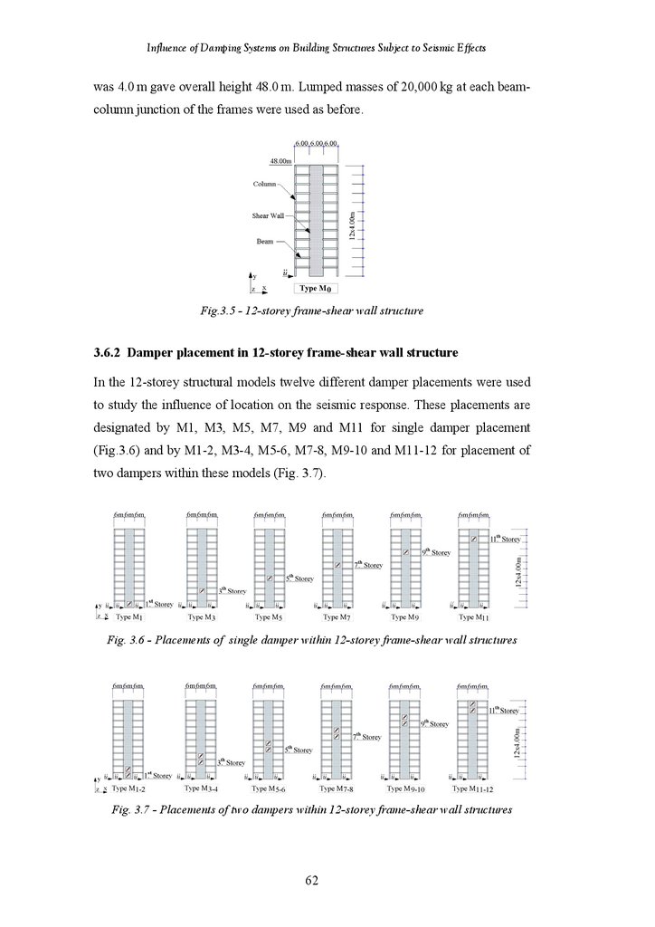
12-Storey Frame Shear Wall Structure
Description of 12-Storey Frame-Shear Wall Structure
Damper Placement in 12-Storey Frame-Shear Wall Structure
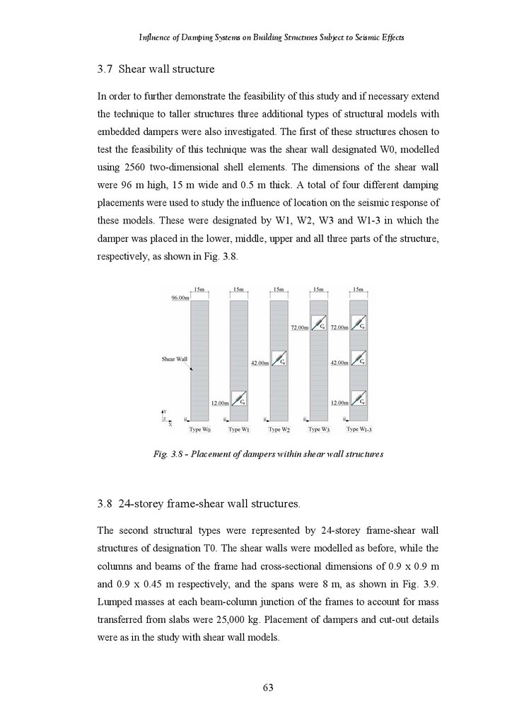
Shear Wall Structure
24-Storey Frame-Shear Wall Structure
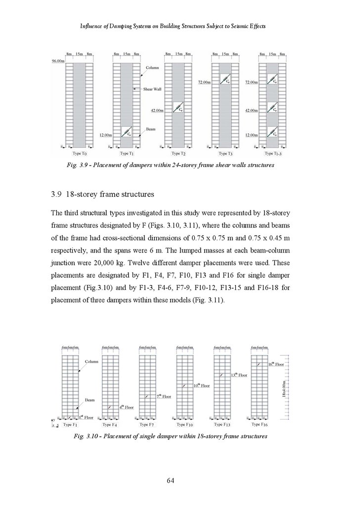
18-Storey Frame Structure
Dampers within 18 and 12-Storey Frame-Shear Wall Structures
Structural Model with Friction Damper-Diagonal Configuration
Structural Model with Viscoelastic Damper-Diagonal Configuration
Structural Model with Friction Damper-Chevron Brace Configuration
Structural Model with Viscoelastic Damper-Chevron Brace Configuration
Structural Model with Hybrid Friction-Viscoelastic Damper
Structural Model with Viscoelastic Damper-Lower Toggle Configuration
Dampers within Shear Wall Structures
Structural Model with Friction Damper-Diagonal Configuration
Structural Model with Viscoelastic Damper-Diagonal Configuration
Structural Model with Friction Damper-Chevron Brace Configuration
Structural Model with Viscoelastic Damper-Chevron Brace Configuration
Structural Model with Hybrid Friction-Viscoelastic Damper
Dampers within 24-Storey Frame-Shear Wall Structures
Dampers within 18-Storey Frame Structures
Input Earthquake Records
Verification of Results
Results of Benchmark Model Testing
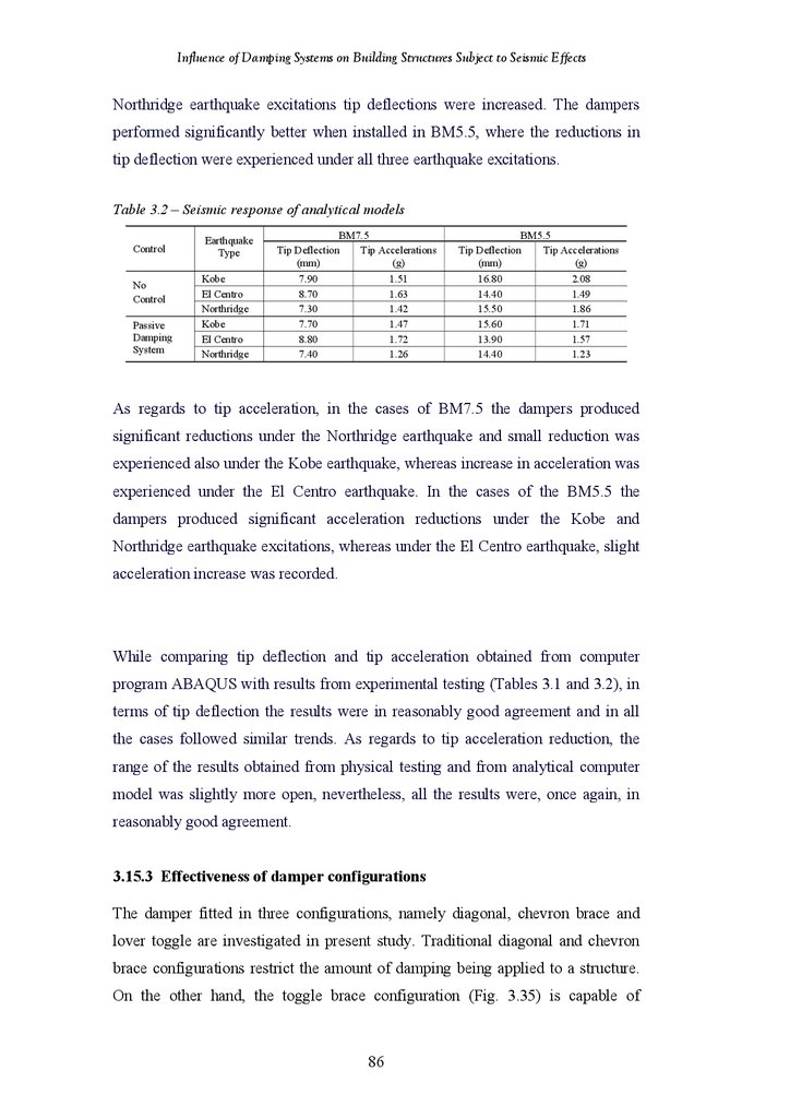
Results of Analytical Investigation of Benchmark Models
Effectiveness of Damper Configurations
Results of Analytical Investigation of Damper Configurations
4.1
4.2
4.3
4.3.1
4.3.2
4.3.3
4.3.4
4.3.5
4.3.6
CHAPTER 4 RESULTS – HIGH RISE STRUCTURES
Introduction
Seismic Response of 96 m High Shear Wall Structure
Seismic Response of 24-Storey Frame-Shear Wall Structure
Damping Properties of Viscoelastic Dampers
Frame-Shear Wall Structure Type T1
Frame-Shear Wall Structure Type T3
Frame-Shear Wall Structure Type T1-3
Parameters of Viscoelastic Dampers - Summary of Finding
Response of T Structure under Five Earthquake Excitations
iv
59
59
60
60
60
61
61
61
62
62
63
64
64
65
66
67
68
69
70
71
72
73
74
75
76
77
77
78
79
80
82
84
85
87
89
92
93
93
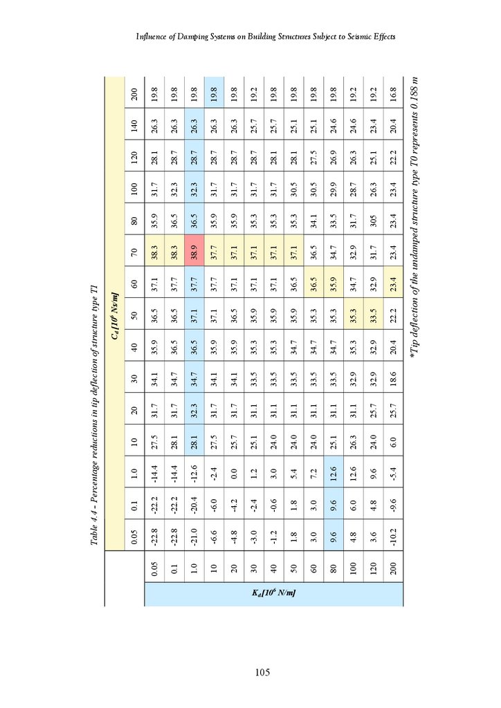
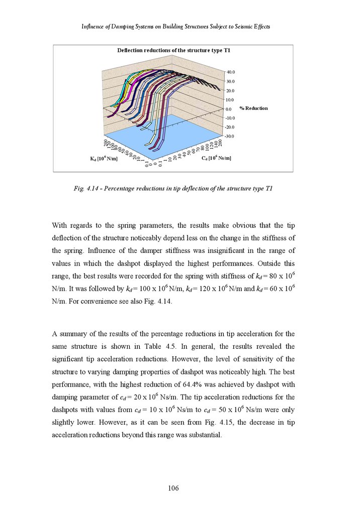
104
104
104
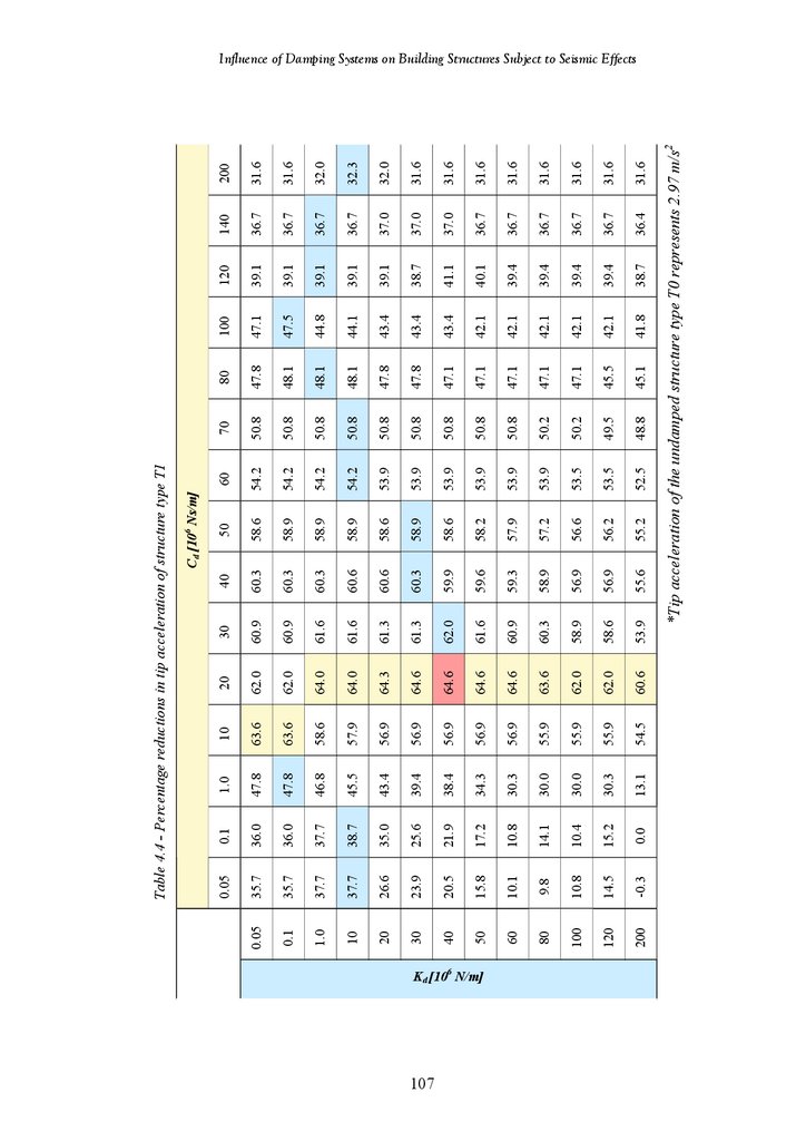
109
114
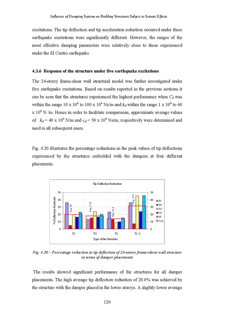
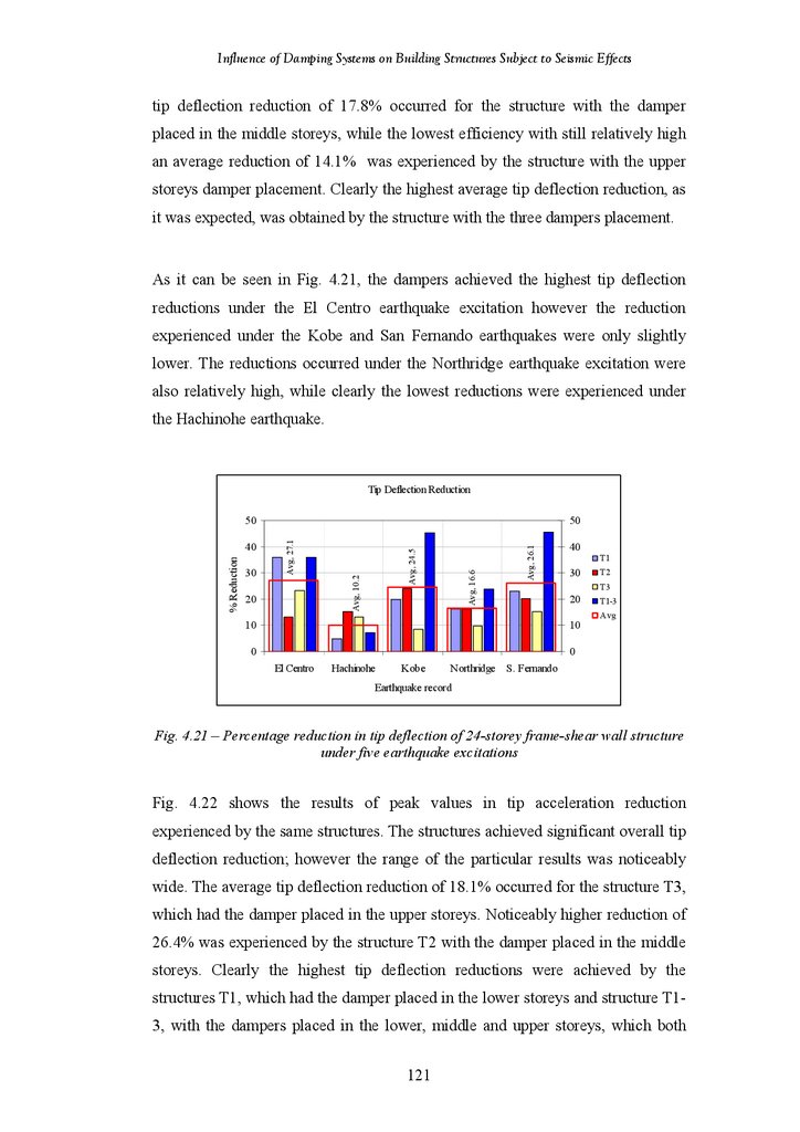
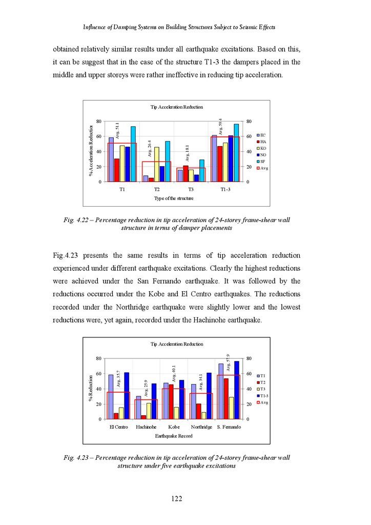
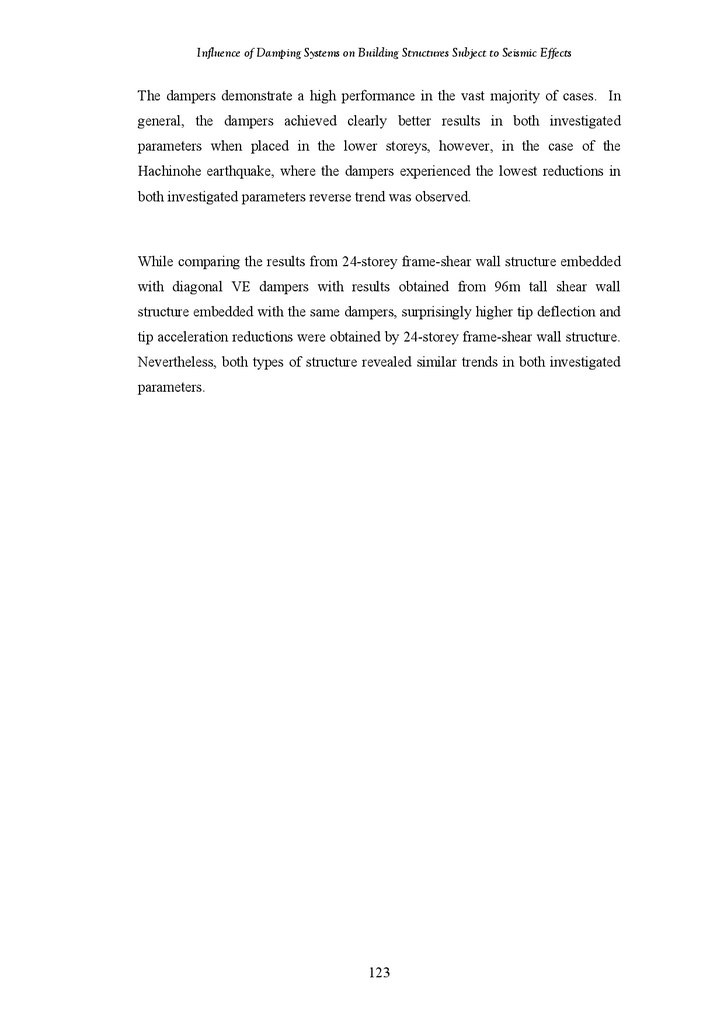
119
121
7.
Influence of Damping Systems on Building Structures Subject to Seismic Effects5.1
5.2
5.2.1
5.2.2
5.2.3
5.2.4
5.2.5
5.2.6
5.2.7
5.2.8
5.3
CHAPTER 5 RESULTS – 18-STOREY STRUCTURES
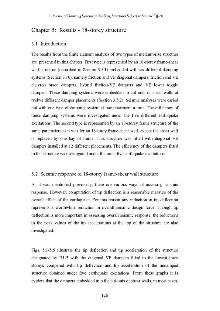
Introduction
Seismic Response of 18-Storey Frame-Shear Wall Structure
Undamped Structure
Diagonal Friction Dampers
Diagonal Viscoelastic Dampers
Chevron Brace Friction Dampers
Chevron Brace Viscoelastic Dampers
Hybrid Friction-Viscoelastic Dampers
Lower Toggle Viscoelastic Dampers
Summary of Findings in 18-Storey Structure
Seismic Response of 18-Storey Frame Structure
126
127
127
131
132
139
146
153
159
166
172
182
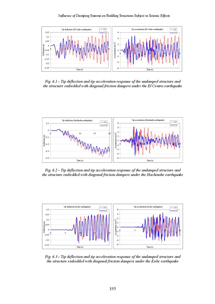
6.1
6.2
6.2.1
6.2.2
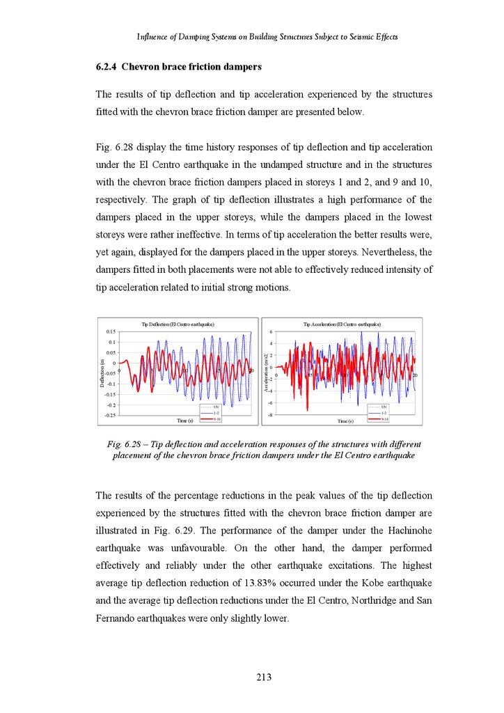
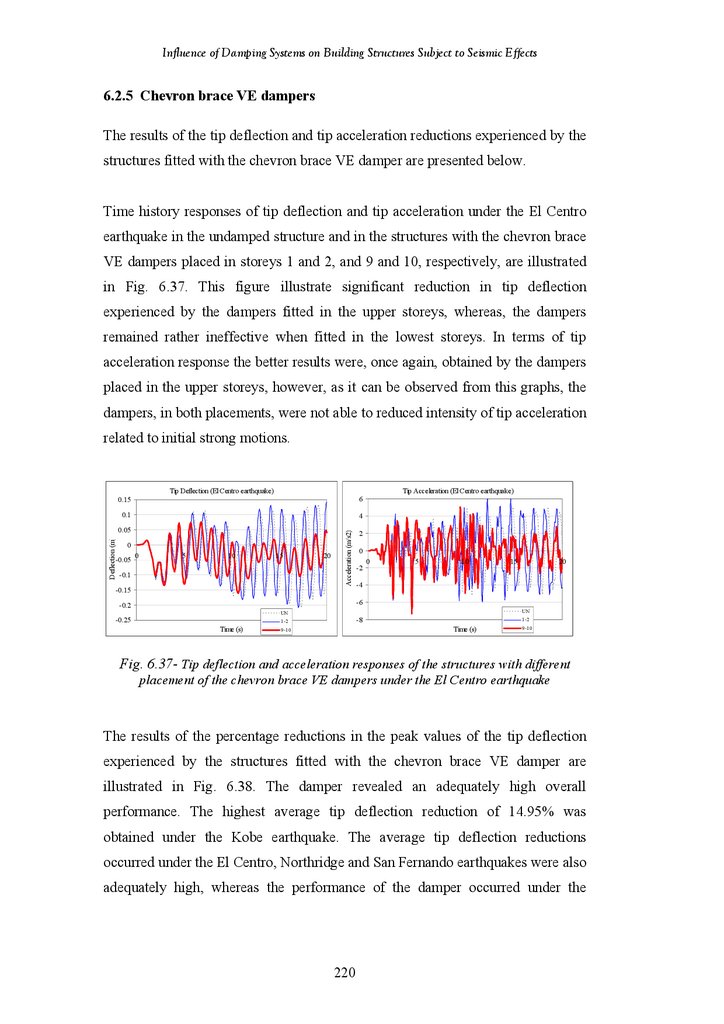
6.2.3
6.2.4
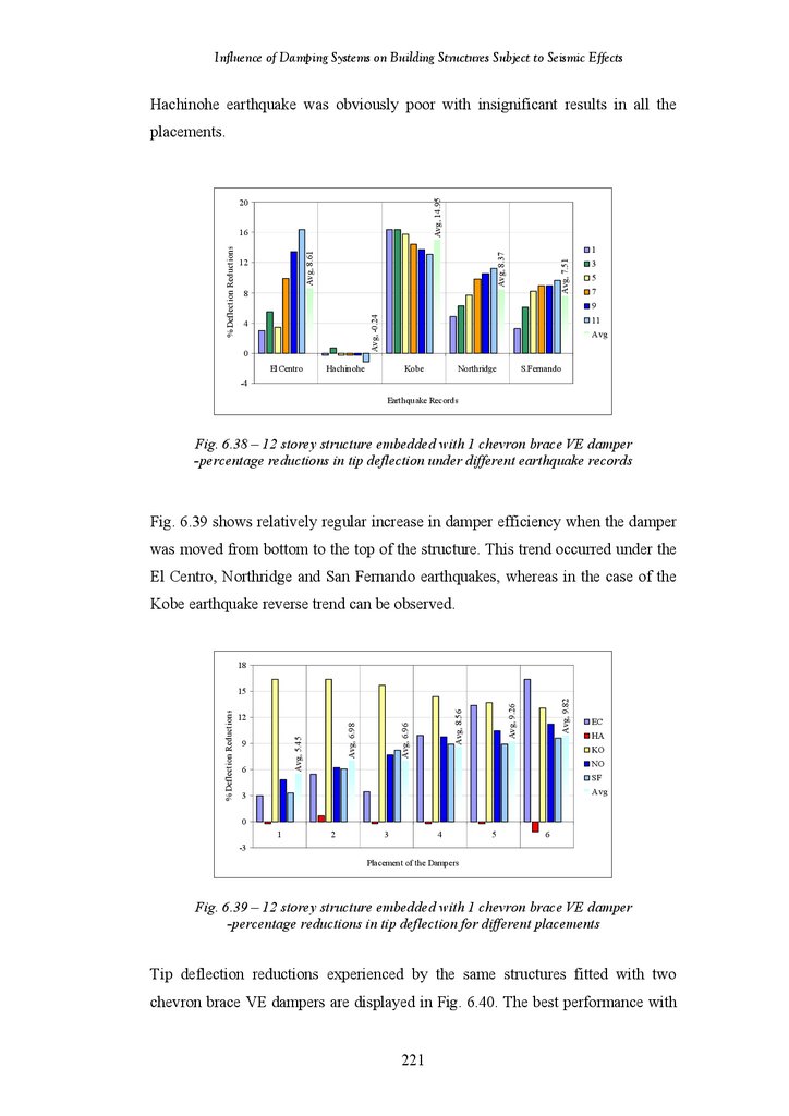
6.2.5
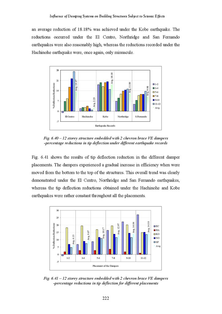
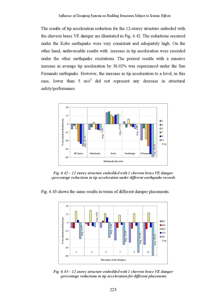
6.2.6
6.2.7
6.2.8
CHAPTER 6 RESULTS – 12-STOREY STRUCTURES
Introduction
Seismic Response of 12-Storey Frame-Shear Wall Structure
Undamped Structure
Diagonal Friction Dampers
Diagonal Viscoelastic Dampers
Chevron Brace Friction Dampers
Chevron Brace Viscoelastic Dampers
Hybrid Friction-Viscoelastic Dampers
Lower Toggle Viscoelastic Dampers
Summary of Findings in 12-Storey Structure
194
195
195
199
200
207
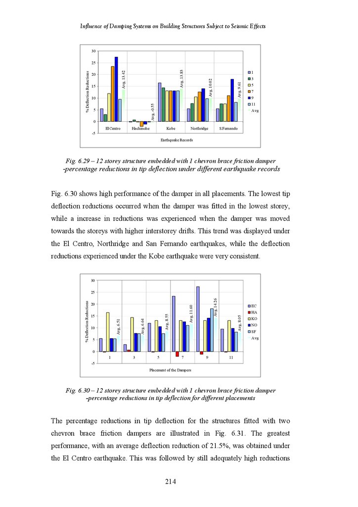
214
221
227
235
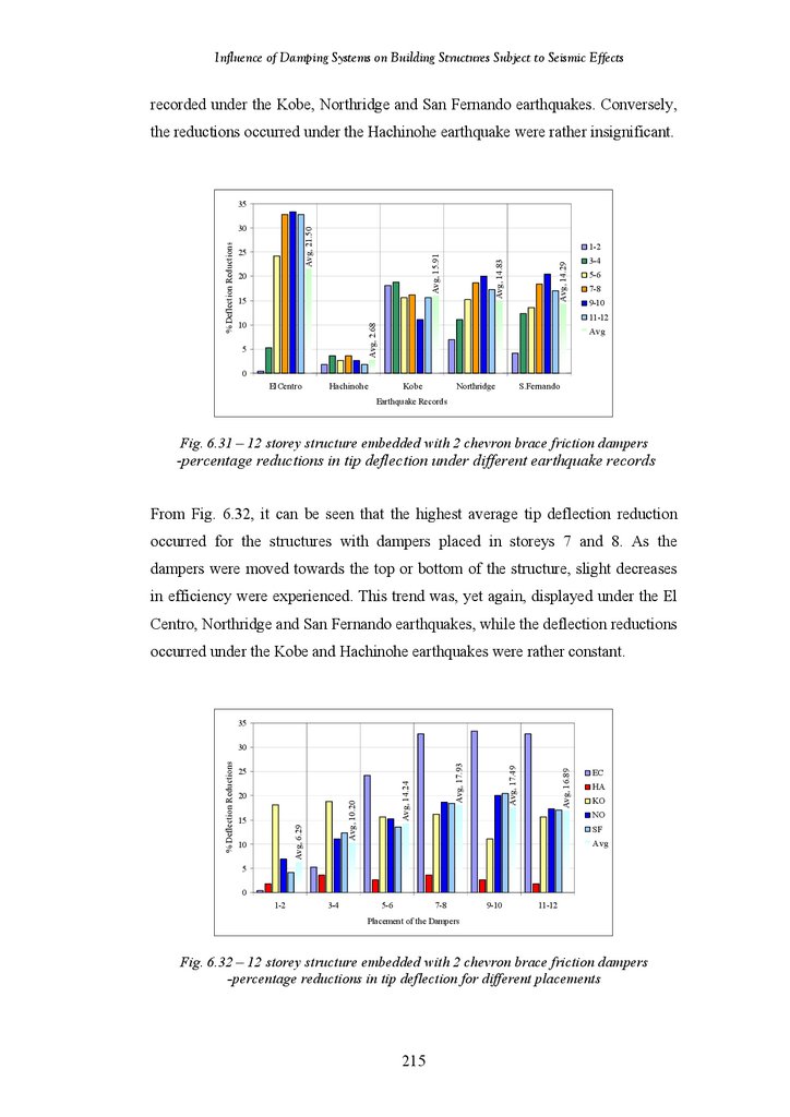
241
7.1
7.2
7.2.1
7.2.2
7.2.3
7.2.4
7.2.5
7.2.6
7.3
CHAPTER 7 CONCLUSIONS AND RECOMMENDATIONS
Scientific Contribution from this Research
Discussions
96 m High Shear Wall structure
24-Storey Frame-Shear Wall Structure
18-Storey Frame-Shear Wall Structure
18-Storey Frame Structure
12-Storey Frame-Shear Wall Structure
Conclusions
Recommendations for Further Research
252
253
254
255
255
257
259
259
261
262
LIST OF REFERENCES
APPENDIX
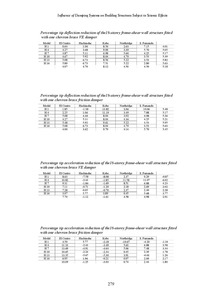
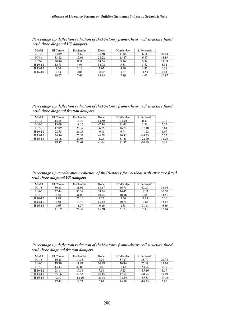
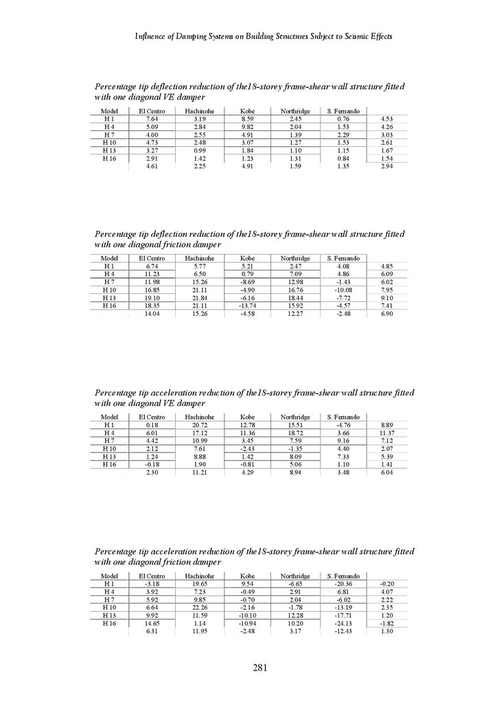
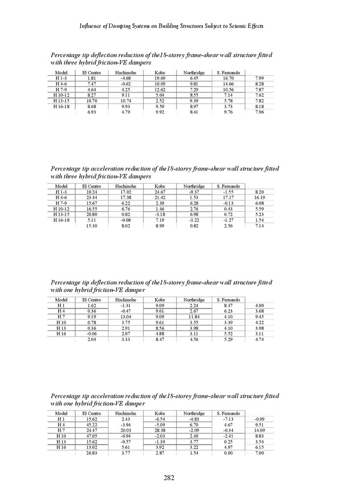
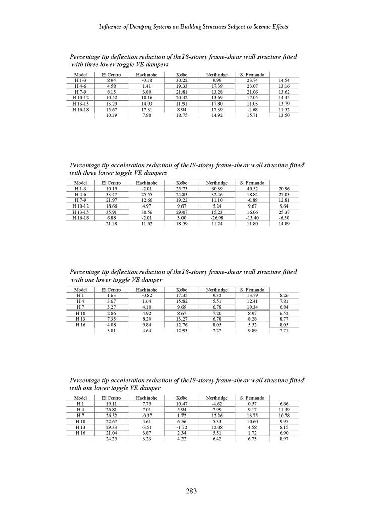
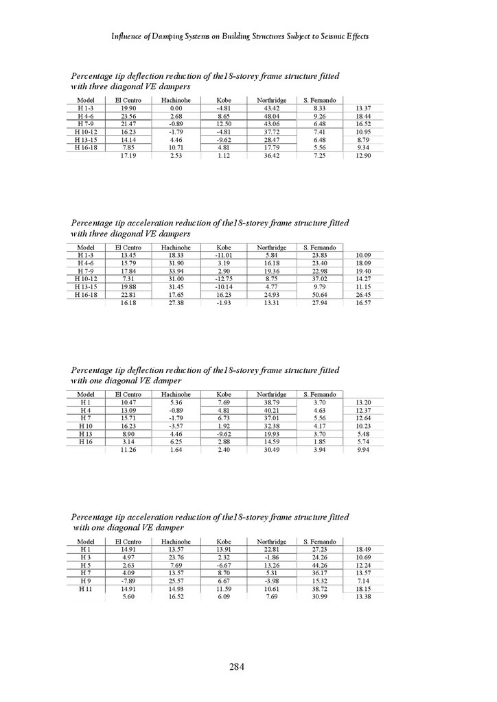
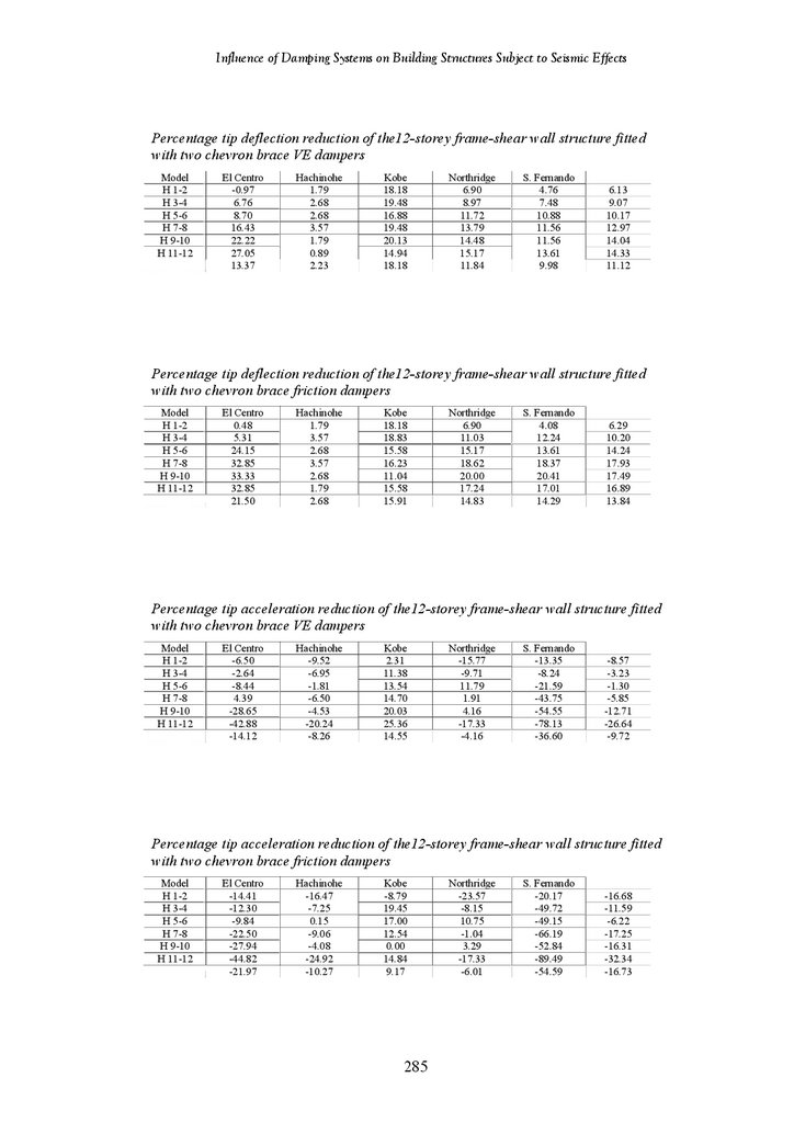
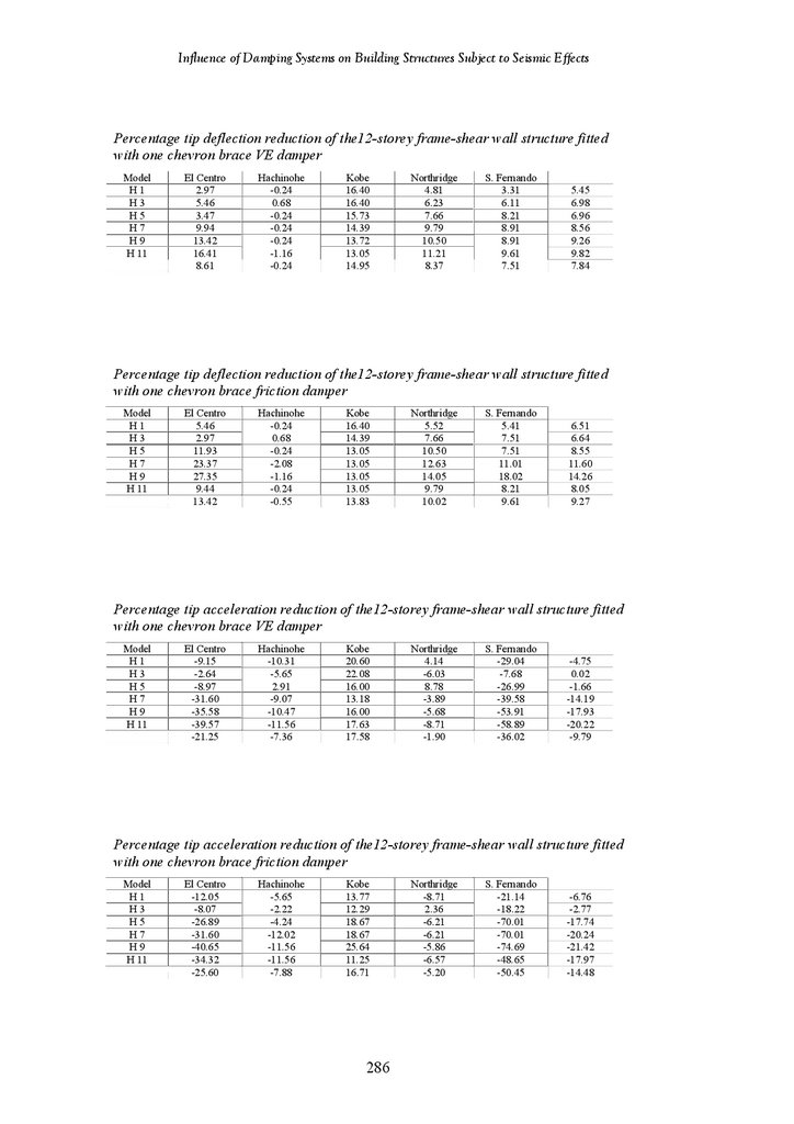
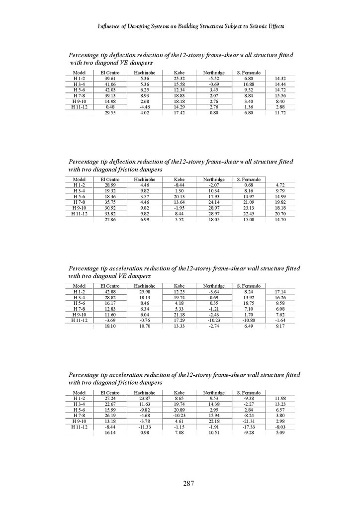
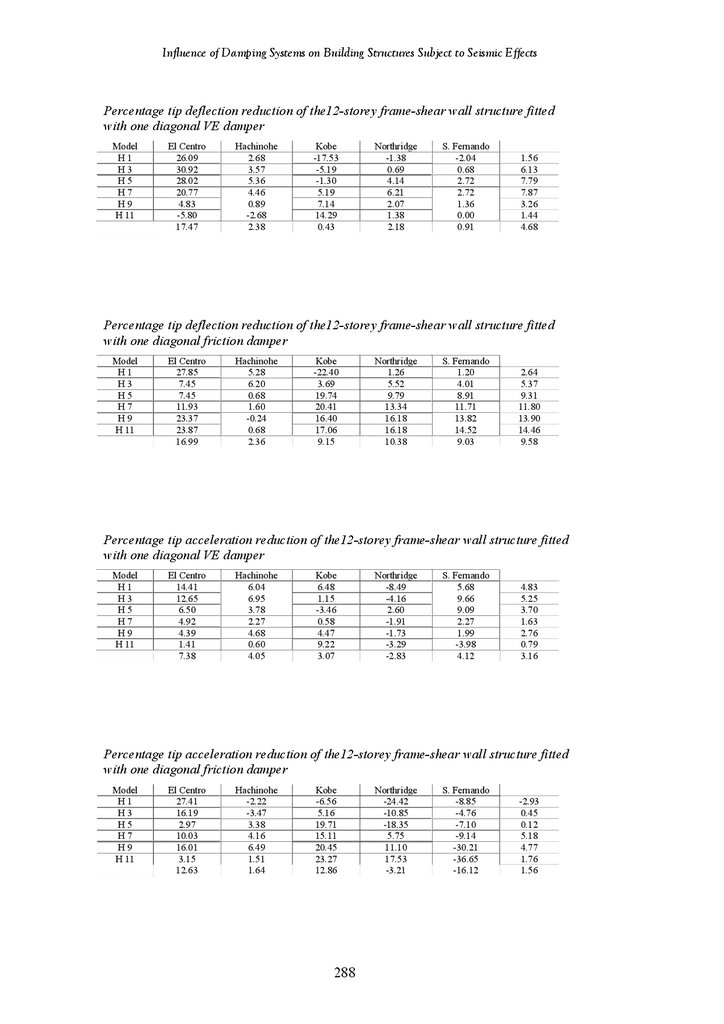
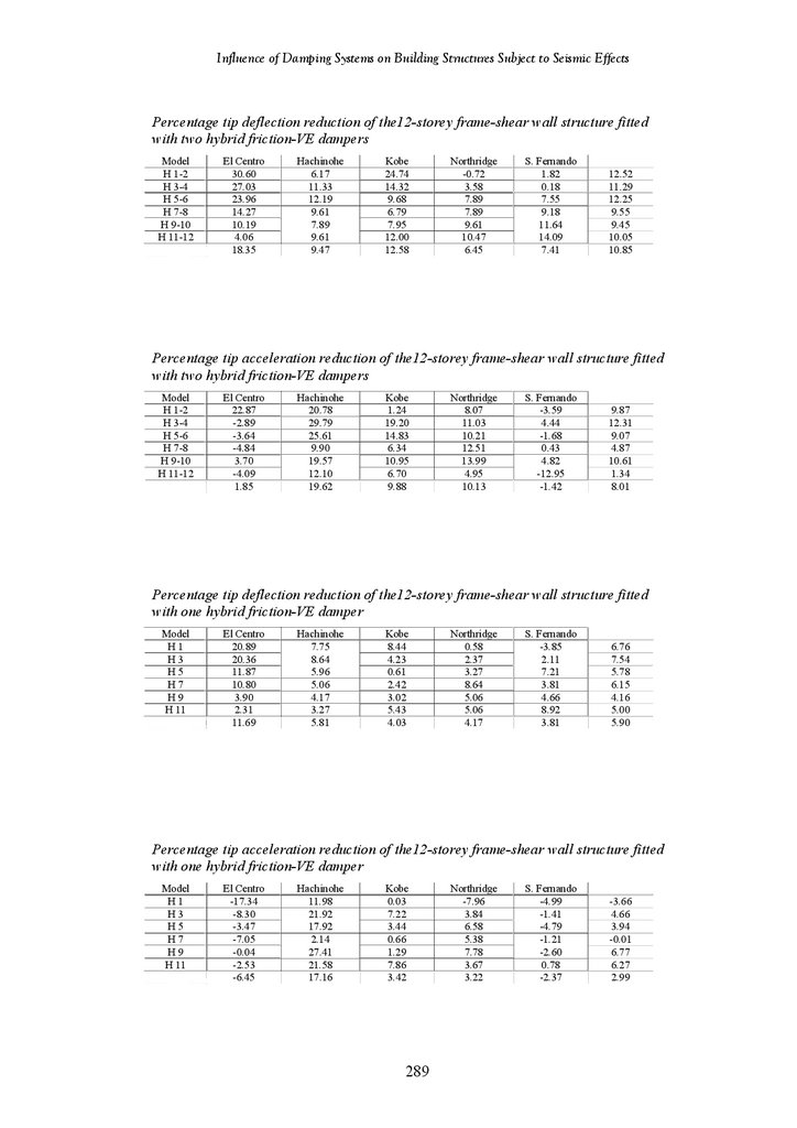
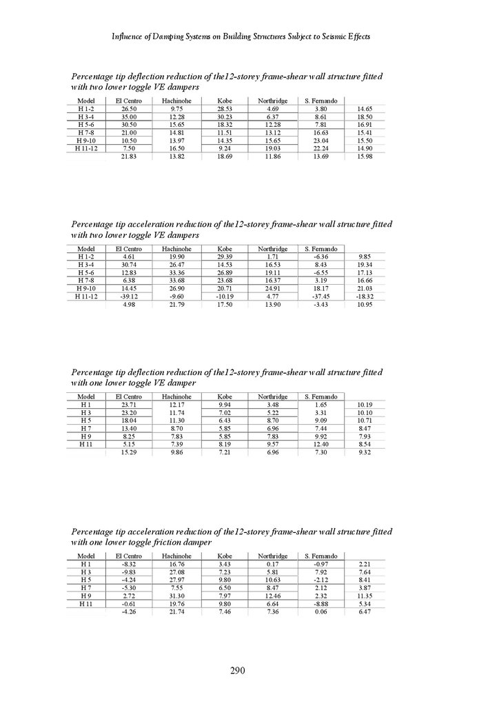
Tables of Results of 18-Storey and 12-Storey Structures
263
279
279
v
8.
Influence of Damping Systems on Building Structures Subject to Seismic EffectsFigures
4
Figure 1.1
Example of Typical Passive Energy Dissipating Devices
Figure 2.1
Figure 2.2
Figure 2.3
Figure 2.4
Figure 2.5
Figure 2.6
Figure 2.7
Figure 2.8
Figure 2.9
Figure 2.10
Figure 2.11
Figure 2.12
Figure 2.13
Figure 2.14
Figure 2.15
Figure 2.16
Figure 2.17
Figure 2.18
Figure 2.19
Figure 2.20
Figure 2.21
Figure 2.22
Figure 2.23
Figure 2.24
Figure 2.25
Figure 2.26
Figure 2.27
Figure 2.28
Figure 2.29
Global Maps of Earthquake Events from Last 30 Years
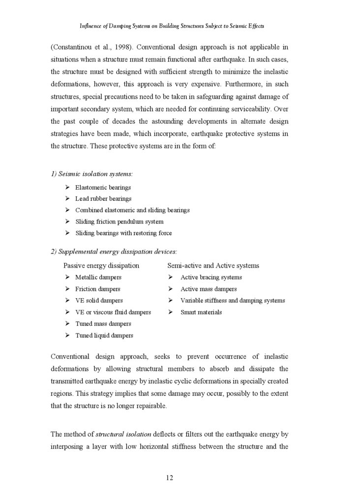
Base Isolation
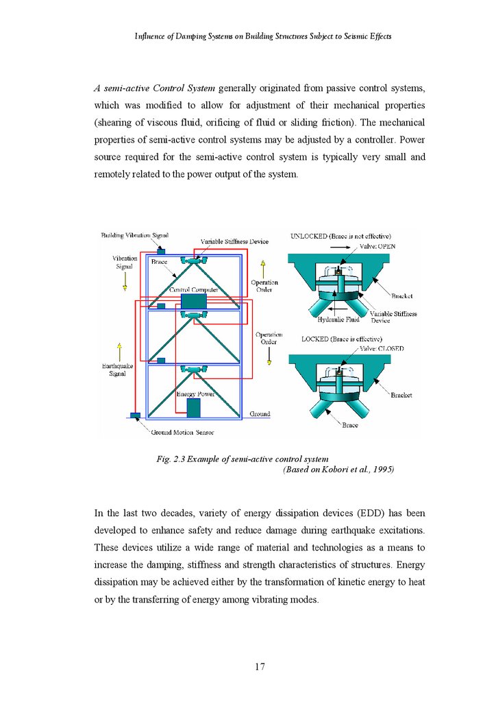
Example of Semi-Active Control System
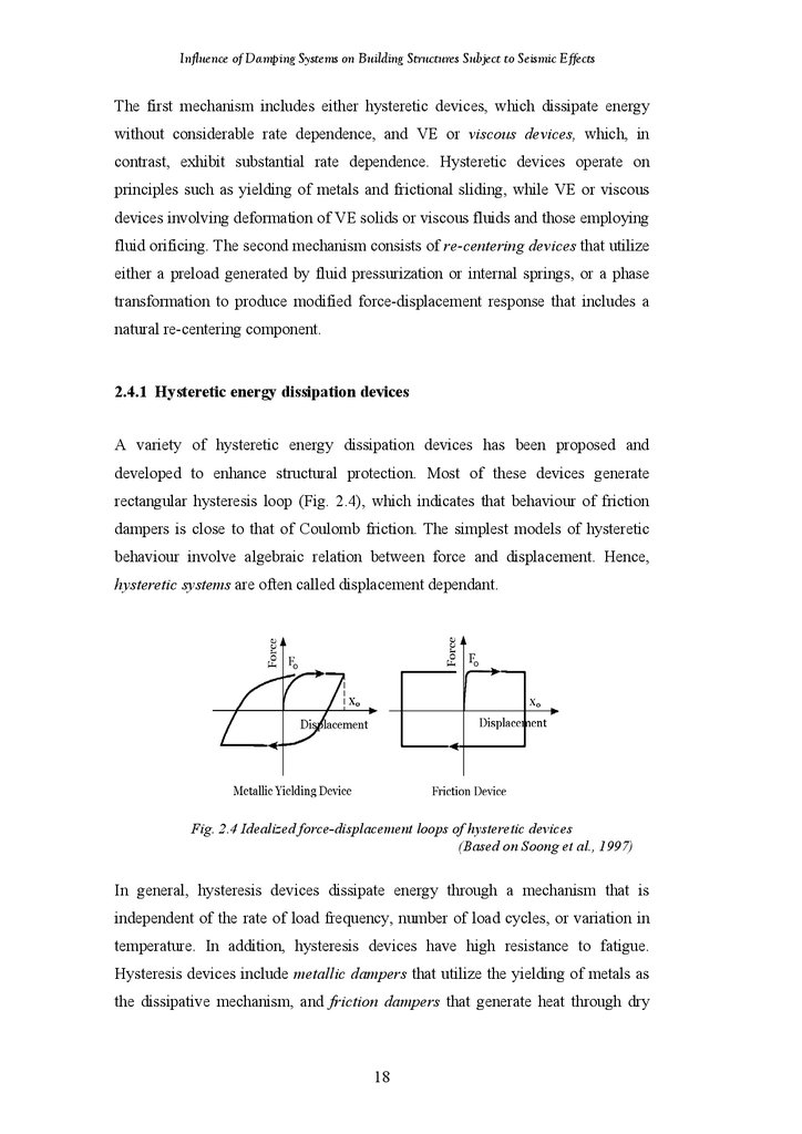
Idealized Force-Displacement Loops of Hysteretic Devices
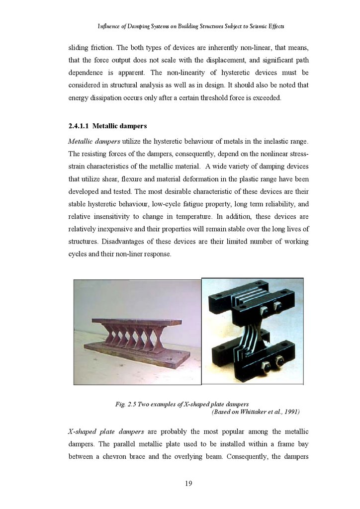
Examples of X-Shaped Plate Dampers
Triangular Shaped Damper and Its Hysteretic Loops
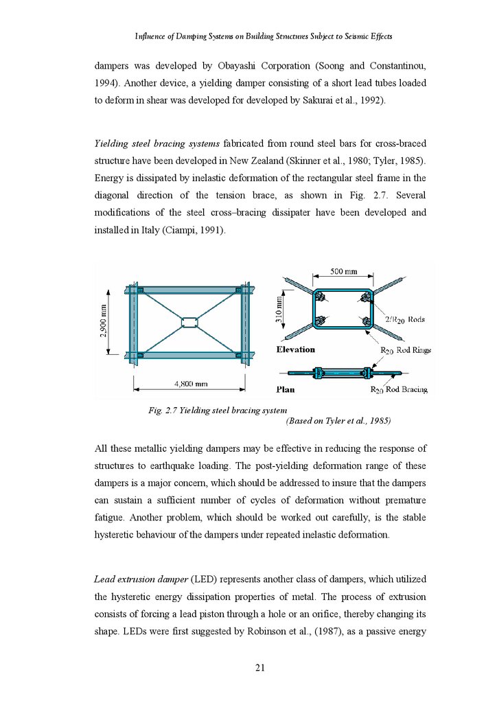
Yielding Steel Bracing System
Examples of Lead Extrusion Devices
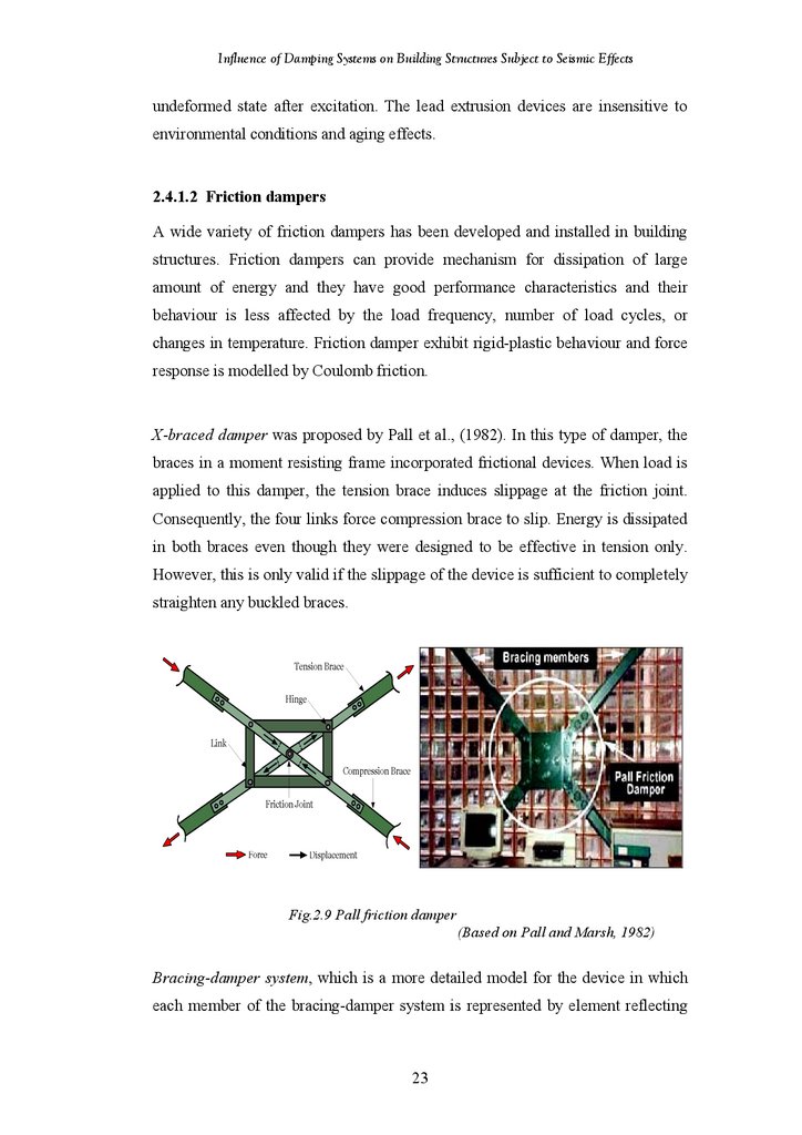
Pall Friction Damper
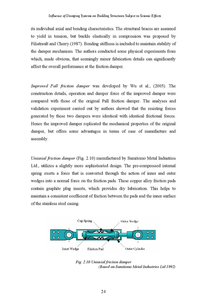
Uniaxial Friction Damper
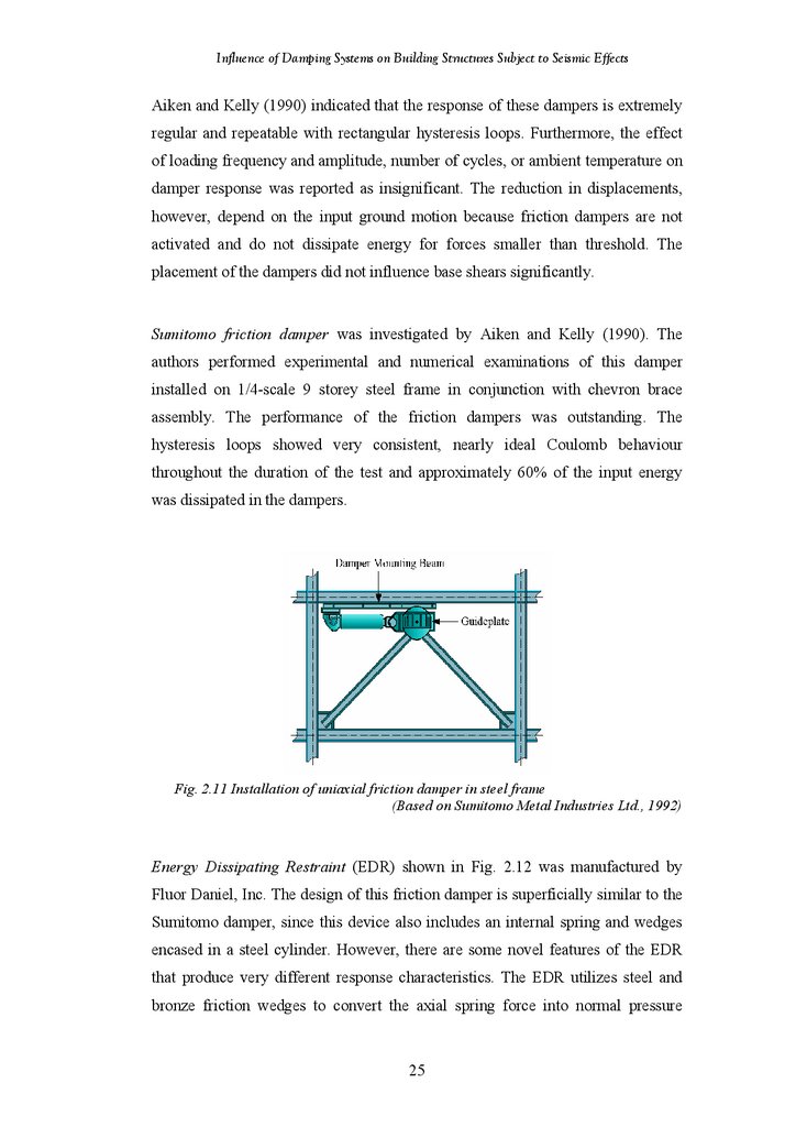
Installation of Uniaxial Friction Damper in Steel Frame
Energy Dissipating Restraint
Three Examples of Slotted Bolted Connections
Idealized Force-Displacement Loops of VE Devices
Typical VE Solid Damper
Idealized Force-Displacement Loops of Viscous Devices
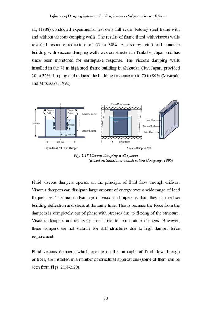
Viscous Damping Wall Systems
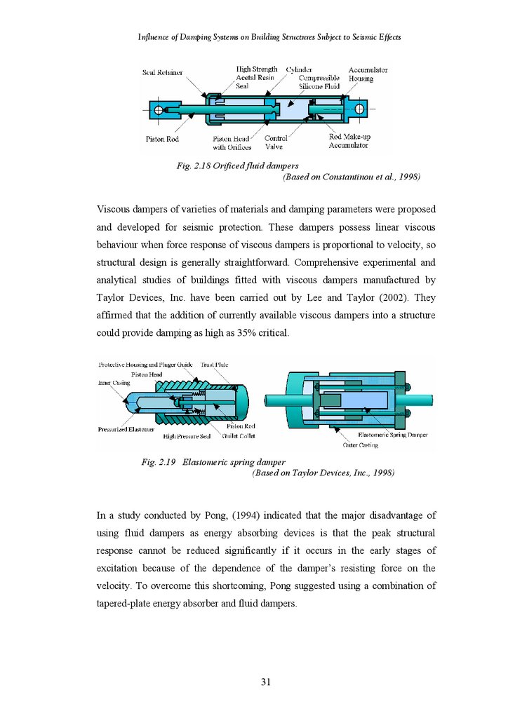
Orificed Fluid Damper
Elastomeric Spring Damper
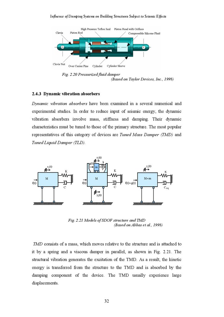
Pressurized Fluid Damper
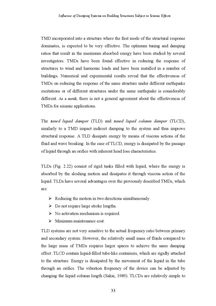
Model of SDOF Structure and TMD
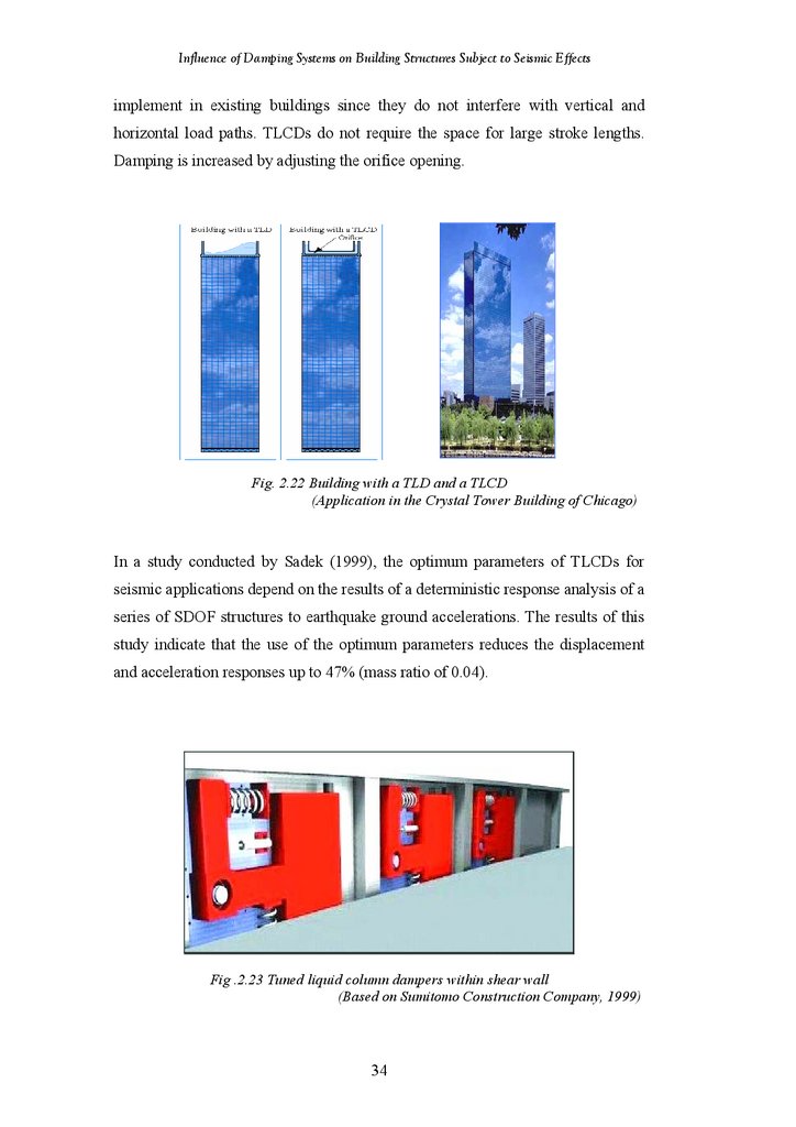
Building with a TLD and a TLCD
Tuned Liquid Column Dampers within Shear Wall
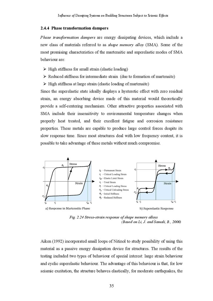
Stress-Strain Response of Shape Memory Alloys
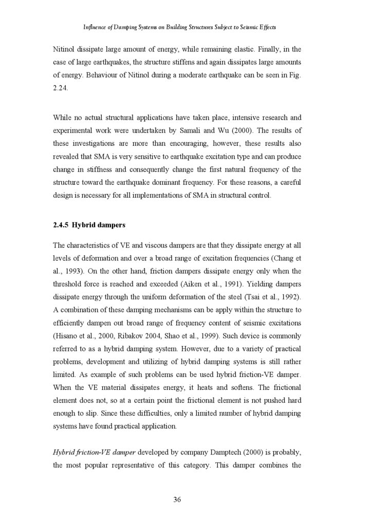
Hybrid Friction-VE Damper
Viscous Damping System – Construction Scheme
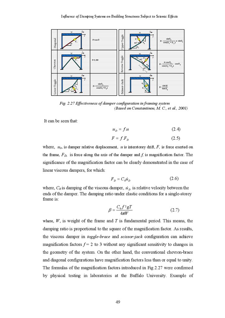
Effectiveness of Damper Configuration in Frame System
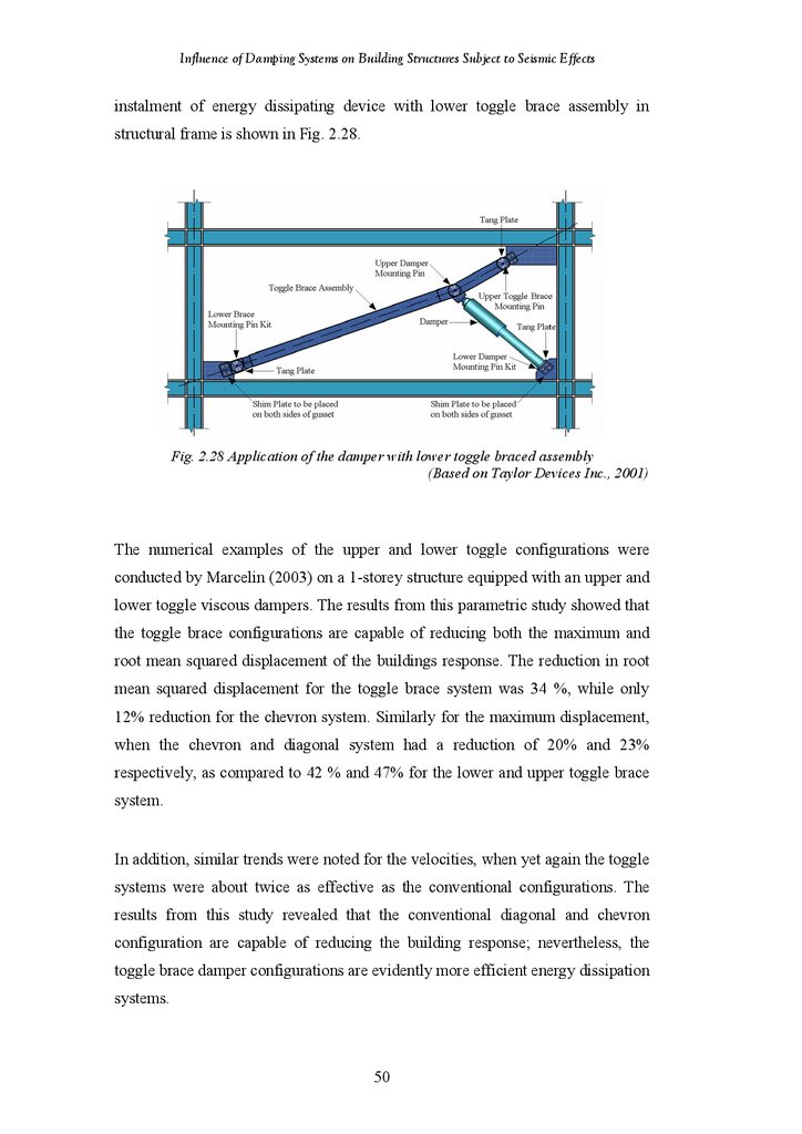
Application of the Damper with Lower Toggle Brace Assembly
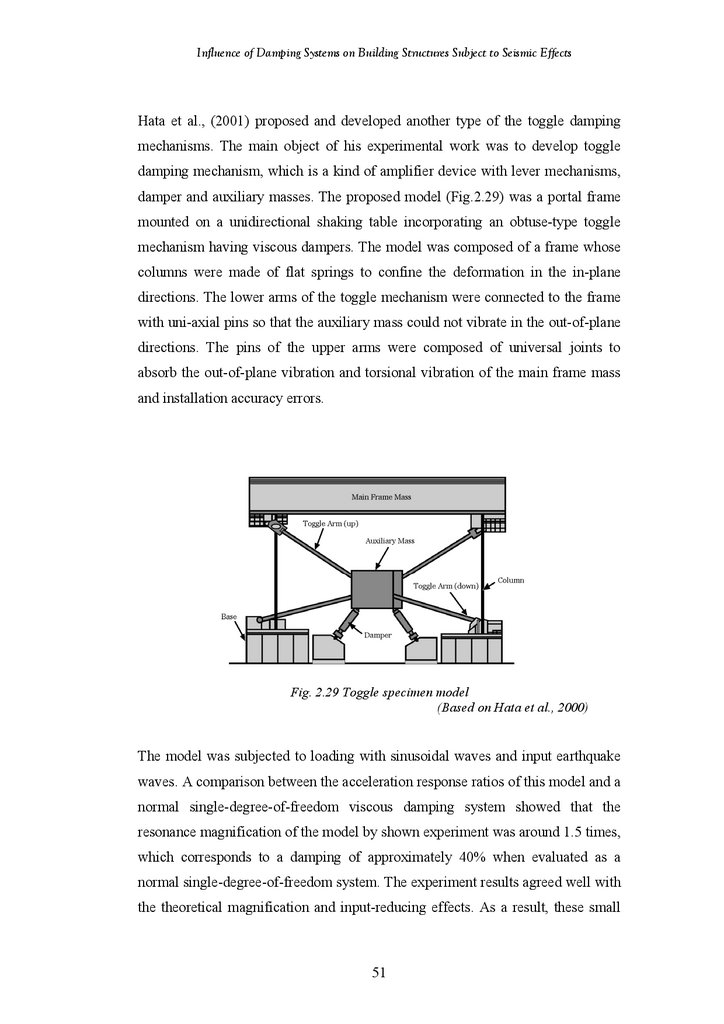
Toggle Specimen Model
11
14
18
19
20
21
22
23
24
25
26
27
27
29
29
28
31
32
32
33
33
35
35
36
38
43
50
51
52
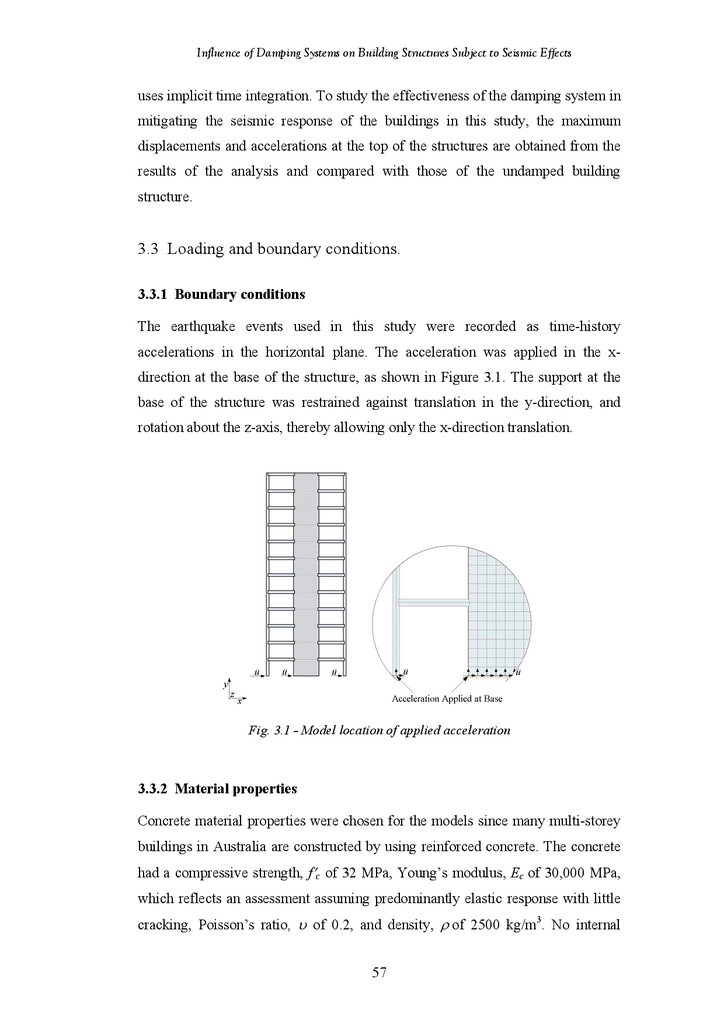
Figure 3.1
Figure 3.2
Figure 3.3
Model Location of Applied Acceleration
18-Storey Frame-Shear Wall Structure
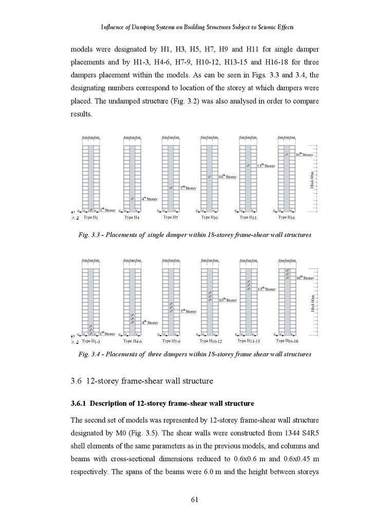
Placement of Single Damper within 18-Storey Frame-Shear Wall
Structure
Placement of Three Dampers within 18-Storey Frame-Shear Wall
Structure
12-Storey Frame-Shear Wall Structure
Placement of Single Damper within 12-Storey Frame-Shear Wall
Structures
Placement of Two Dampers within 12-Storey Frame-Shear Wall
Structures
Placement of Dampers within Shear Wall Structures
Placement of Dampers within 24-Storey Frame-Shear Wall Structures
Placement of Single Damper within 18-Storey Frame Structures
Placement of Three Dampers within 18-Storey Frame Structures
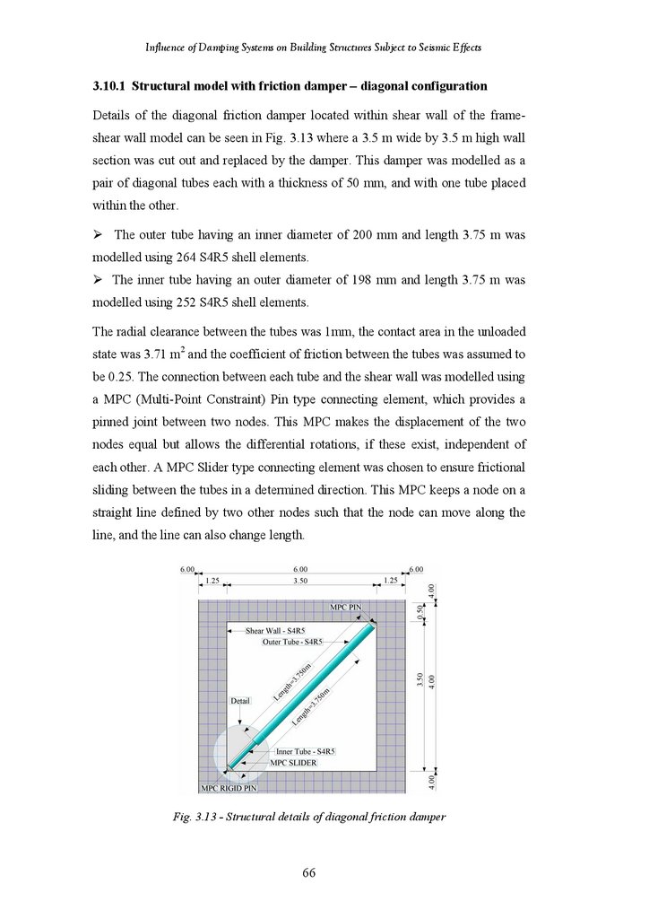
Damping Systems Installed in Medium-Rise Structures
Structural Details of Diagonal Friction Damper
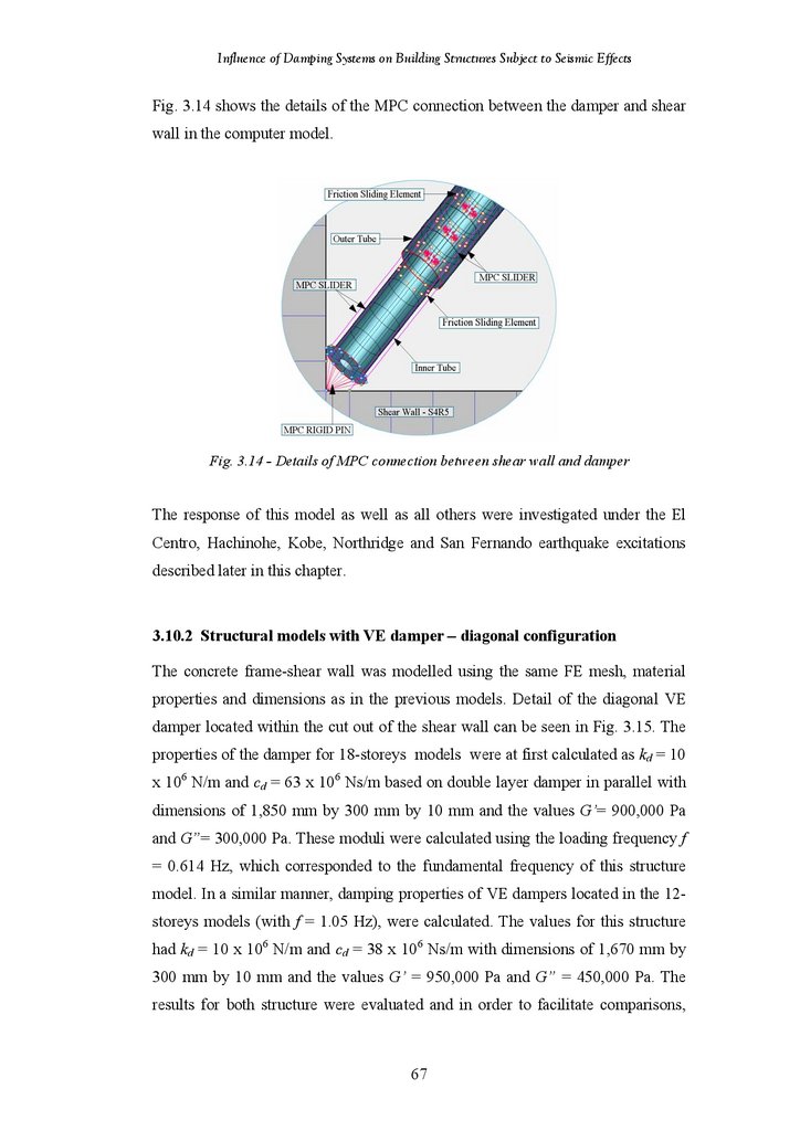
Detail of MPC Connection between Shear Wall and Damper
Structural Details of Diagonal VE Damper
58
61
62
Figure 3.4
Figure 3.5
Figure 3.6
Figure 3.7
Figure 3.8
Figure 3.9
Figure 3.10
Figure 3.11
Figure 3.12
Figure 3.13
Figure 3.14
Figure 3.15
vi
62
63
63
63
64
65
65
66
66
67
68
69
9.
Influence of Damping Systems on Building Structures Subject to Seismic EffectsFigure 3.16
Figure 3.17
Figure 3.18
Figure 3.19
Figure 3.20
Figure 3.21
Figure 3.22
Figure 3.23
Figure 3.24
Figure 3.25
Figure 3.26
Figure 3.27
Figure 3.28
Figure 3.29
Figure 3.30
Figure 3.31
Figure 3.32
Figure 3.33
Figure 3.34
Figure 3.35
Figure 3.36
Figure 4.1
Figure 4.2
Figure 4.3
Figure 4.4
Figure 4.5
Figure 4.6
Figure 4.7
Figure 4.8
Figure 4.9
Figure 4.10
Figure 4.11
Figure 4.12
Figure 4.13
Figure 4.14
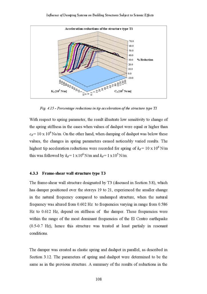
Figure 4.15
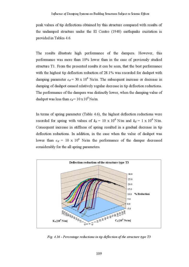
Figure 4.16
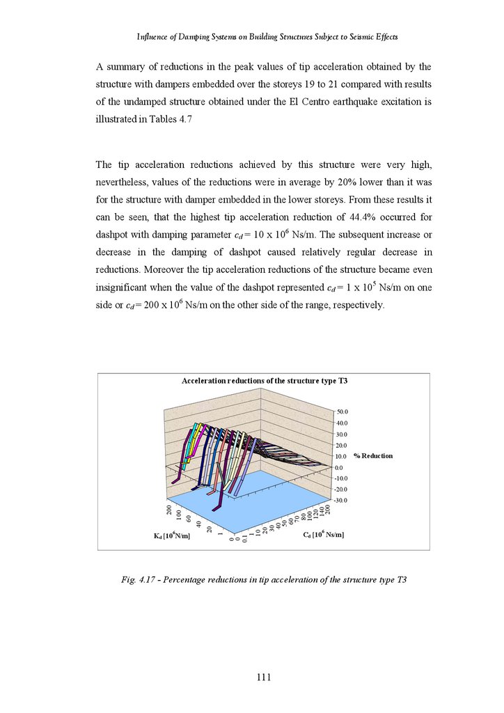
Figure 4.17
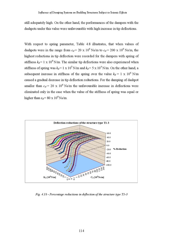
Figure 4.18
Figure 4.19
Structural Details of Chevron Brace Friction Damper
Structural Details of Chevron Brace Viscoelastic Damper
Structural Details of Hybrid Friction-Viscoelastic Damper
Structural Details of Lower Toggle Viscoelastic Damper
Damping Systems installed in Shear Wall Structure
Details of Diagonal Friction Damper within Structure Type W
Details of Diagonal Viscoelastic Damper within Structure Type W
Details of Chevron Brace Friction Damper within Structure Type W
Details of Chevron Brace Viscoelastic Damper within Structure Type W
Details of Hybrid Friction-Viscoelastic Damper within Structure Type W
Details of Diagonal Viscoelastic Damper within Structure Type T
Details of Diagonal Viscoelastic Damper within Structure Type F
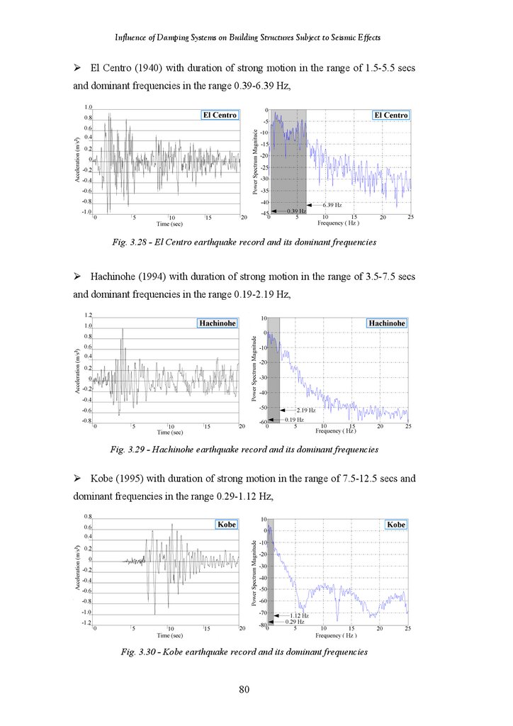
The El Centro Earthquake Record and Its Dominant Frequencies
The Hachinohe Earthquake Record and Its Dominant Frequencies
The Kobe Earthquake Record and Its Dominant Frequencies
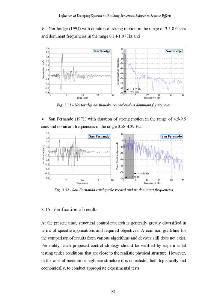
The Northridge Earthquake Record and Its Dominant Frequencies
The San Fernando Earthquake Record and Its Dominant Frequencies
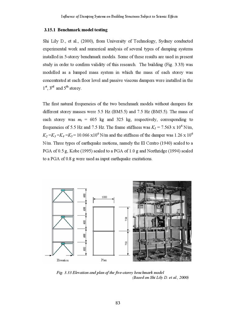
Elevation and Plan View of Five-Storey Benchmark Model
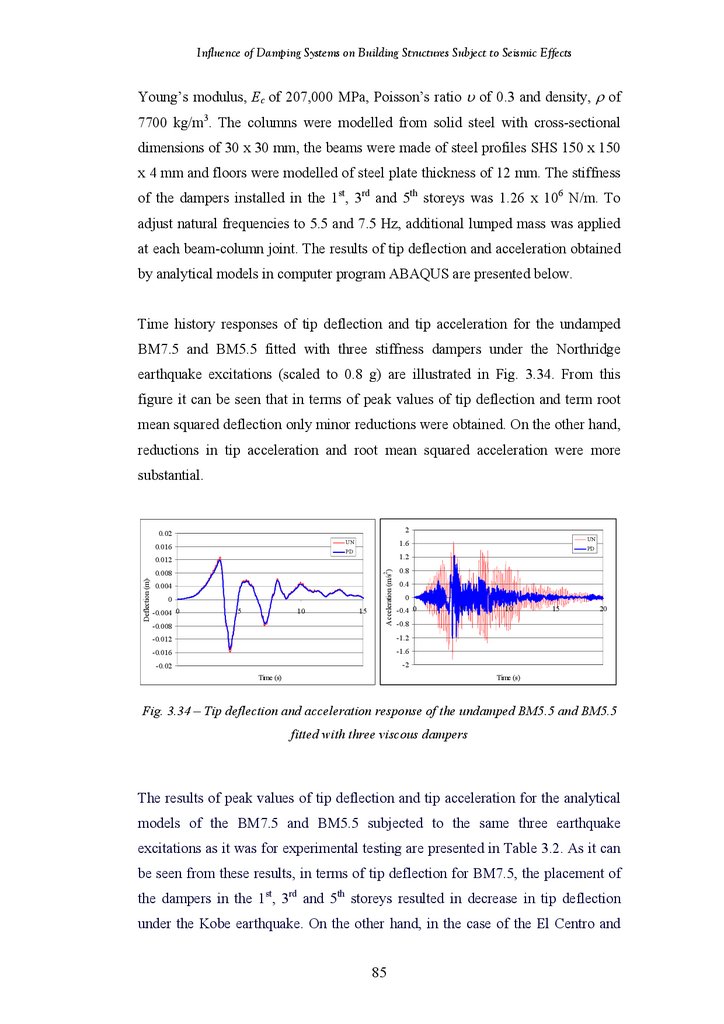
Tip Deflection and Acceleration of the Undamped Benchmark Model and
Benchmark model Fitted with Three Stiffness Dampers
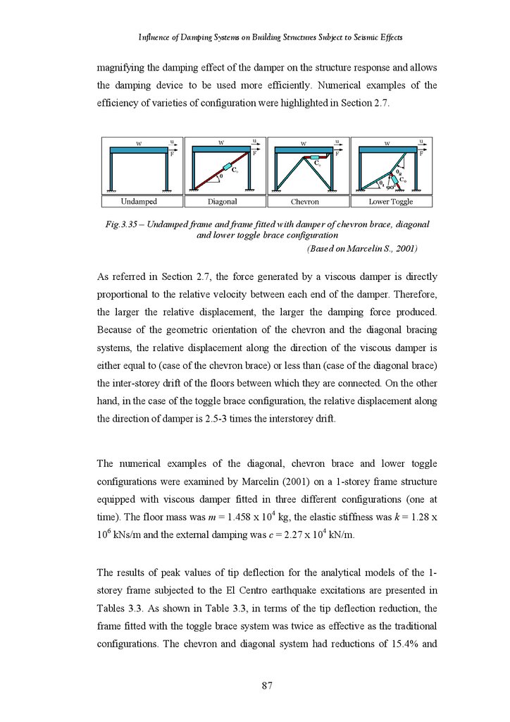
Undamped Frame and Frame with Damper of Chevron Brace, Diagonal
and Lower Toggle Configuration
Tip Deflection of the Undamped Frame and the Frame Fitted with Viscous
Damper of Lower Toggle Configuration
70
71
72
73
74
74
75
76
77
78
79
80
81
81
81
82
82
84
86
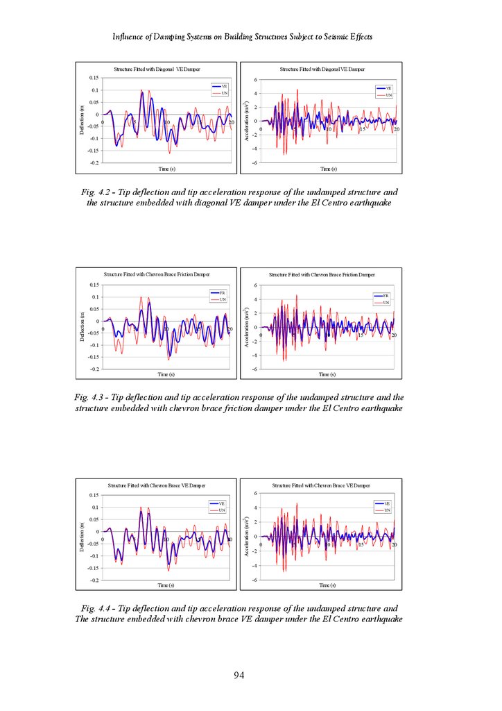
Tip Deflection and Acceleration Response of Undamped Structure and
Structure Fitted with Diagonal Friction Damper under the El Centro
Earthquake
Tip Deflection and Acceleration Response of Undamped Structure and
Structure Fitted with Diagonal VE Damper under the El Centro
Earthquake
Tip Deflection and Acceleration Response of Undamped Structure and
Structure Fitted with Chevron Brace Friction Damper under the El Centro
Earthquake
Tip Deflection and Acceleration Response of Undamped Structure and
Structure Fitted with Chevron Brace Friction Damper under the El Centro
Earthquake
Tip Deflection and Acceleration Response of Undamped Structure and
Structure Fitted with Hybrid Friction-VE Damper under the El Centro
Earthquake
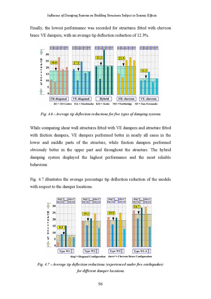
Tip Deflection Reductions for Five Types of Damping Systems
Tip Deflection Reductions for Different Damper Location
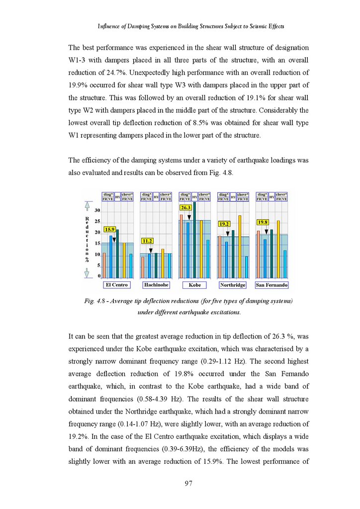
Tip Deflection Reductions under Different Earthquake Excitations
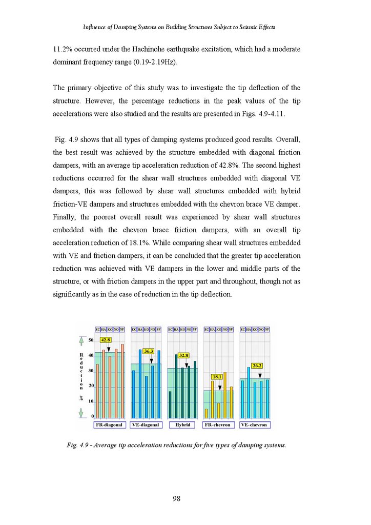
Tip Acceleration Reductions for Five Types of Damping Systems
Tip Acceleration Reductions for Different Damper Location
Tip Acceleration Reductions under Different Earthquake Excitations
Percentage Reductions in Tip Deflection of All Shear Wall Structures
Percentage Reductions in Tip Acceleration of All Shear Wall Structures
Percentage Reductions in Tip Deflection of Structures Type T1
Percentage Reductions in Tip Acceleration of Structures Type T1
Percentage Reductions in Tip Deflection of Structures Type T3
Percentage Reductions in Tip Acceleration of Structures Type T3
Percentage Reductions in Tip Deflection of Structures Type T1-3
Percentage Reductions in Tip Acceleration of Structures Type T1-3
94
vii
88
89
95
95
95
96
97
97
99
99
100
100
102
103
107
109
110
112
115
117
10.
Influence of Damping Systems on Building Structures Subject to Seismic EffectsFigure 4.20
Figure 4.21
Figure 4.22
Figure 4.23
Figure 5.1
Figure 5.2
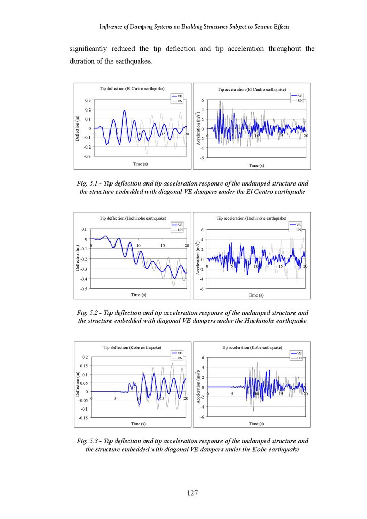
Figure 5.3
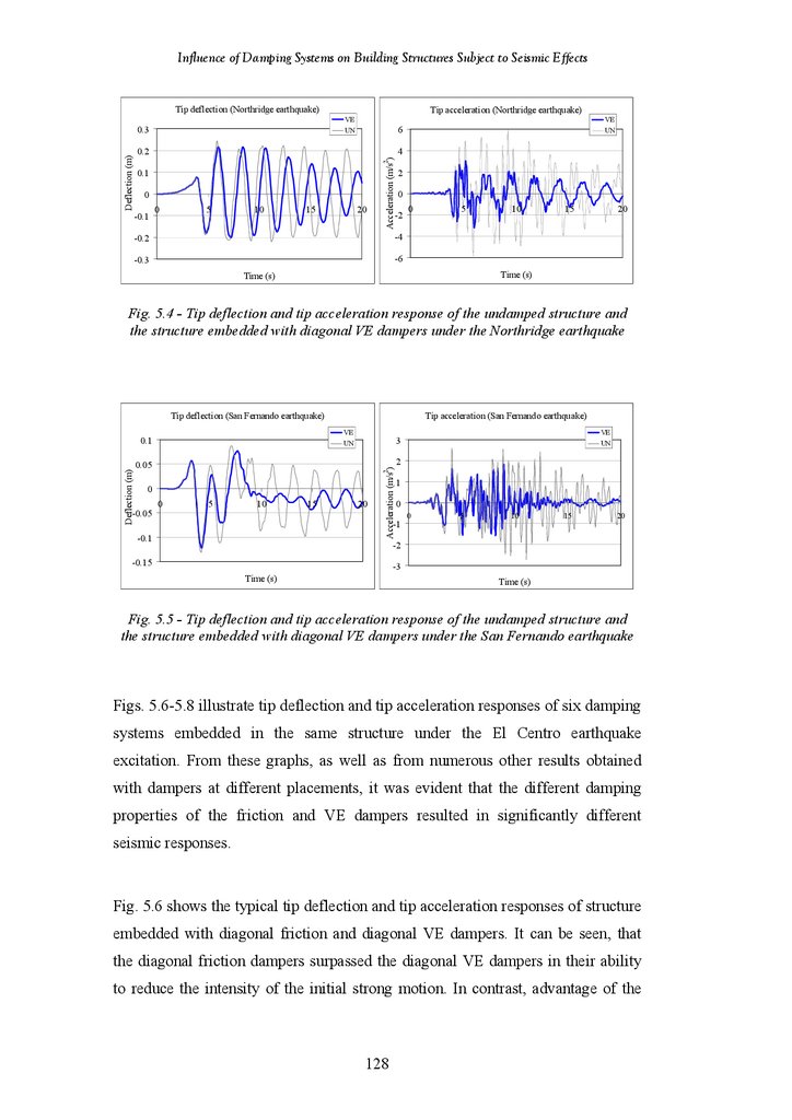
Figure 5.4
Figure 5.5
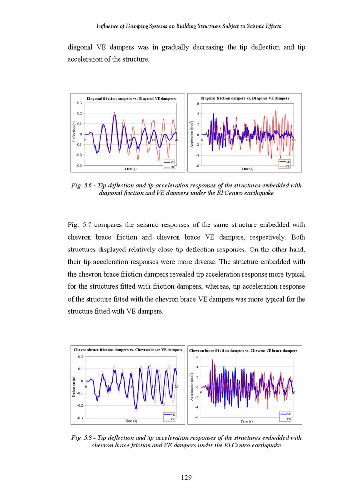
Figure 5.6
Figure 5.7
Figure 5.8
Figure 5.9
Figure 5.10
Figure 5.11
Figure 5.12
Figure 5.13
Figure 5.14
Figure 5.15
Figure 5.16
Figure 5.17
Figure 5.18
Figure 5.19
Figure 5.20
Percentage Reduction in Tip Deflection of 24-Storey Frame-Shear Wall
Structure in Terms of Damper Placement
Percentage Reduction in Tip Deflection of 24-Storey Frame-Shear Wall
Structure under Five Earthquake Excitations
Percentage Reduction in Tip Acceleration of 24-Storey Frame-Shear Wall
Structure in Terms of Damper Placement
Percentage Reduction in Tip Acceleration of 24-Storey Frame-Shear Wall
Structure under Five Earthquake Excitations
118
Tip Deflection and Acceleration Response of Undamped Structure and
Structure Fitted with Diagonal VE Damper under the El Centro
Earthquake
Tip Deflection and Acceleration Response of Undamped Structure and
Structure Fitted with Diagonal VE Damper under the Hachinohe
Earthquake
Tip Deflection and Acceleration Response of Undamped Structure and
Structure Fitted with Diagonal VE Damper under the Kobe Earthquake
Tip Deflection and Acceleration Response of Undamped Structure and
Structure Fitted with Diagonal VE Damper under the Northridge
Earthquake
Tip Deflection and Acceleration Response of Undamped Structure and
Structure Fitted with Diagonal VE Damper under the San Fernando
Earthquake
Tip Deflection and Acceleration Response of Structures fitted with
Diagonal Friction and VE Dampers under the El Centro Earthquake
Tip Deflection and Acceleration Response of Structures fitted with
Chevron Brace Friction and VE Dampers under the El Centro Earthquake
Tip Deflection and Acceleration Response of Structures fitted with Hybrid
Friction-VE Damper and Lower Toggle VE Dampers under the El Centro
Earthquake
Interstorey Drifts of Undamped Structure under Five Earthquake
Excitations
Tip Deflection and Acceleration Response of the structures with Different
Placement of the Diagonal Friction Dampers under the El Centro
Earthquake
18-Storey Structure Fitted with 1 Diagonal Friction Damper – Percentage
Reductions in Tip Deflection under Different Earthquake Records
18-Storey Structure Fitted with 1 Diagonal Friction Damper – Percentage
Reductions in Tip Deflection for Different Damper Placements
18-Storey Structure Fitted with 3 Diagonal Friction Dampers – Percentage
Reductions in Tip Deflection under Different Earthquake Records
18-Storey Structure Fitted with 3 Diagonal Friction Dampers – Percentage
Reductions in Tip Deflection for Different Damper Placements
18-Storey Structure Fitted with 1 Diagonal Friction Damper – Percentage
Reductions in Tip Acceleration under Different Earthquake Records
18-Storey Structure Fitted with 1 Diagonal Friction Damper – Percentage
Reductions in Tip Acceleration for Different Damper Placements
18-Storey Structure Fitted with 3 Diagonal Friction Dampers – Percentage
Reductions in Tip Acceleration under Different Earthquake Records
18-Storey Structure Fitted with 3 Diagonal Friction Dampers – Percentage
Reductions in Tip Acceleration for Different Damper Placements
Tip Deflection and Acceleration Responses of the structures with Different
Placement of the Diagonal VE Dampers under the El Centro Earthquake
18-Storey Structure Fitted with 1 Diagonal VE Damper – Percentage
Reductions in Tip Deflection under Different Earthquake Records
128
viii
122
123
123
128
128
129
129
130
130
131
132
133
133
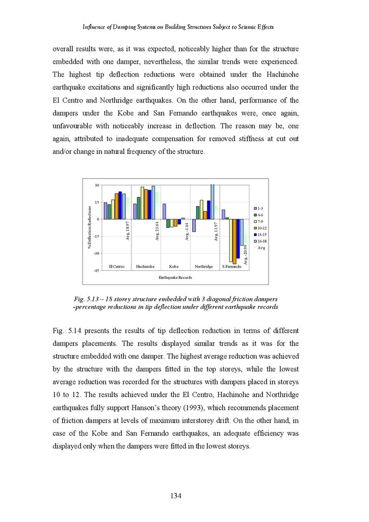
134
135
136
136
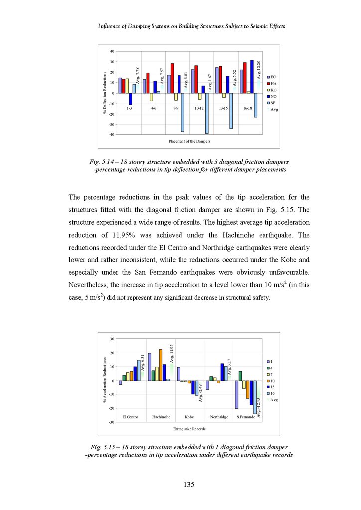
137
137
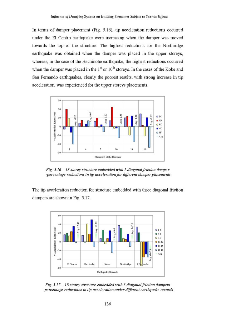
138
139
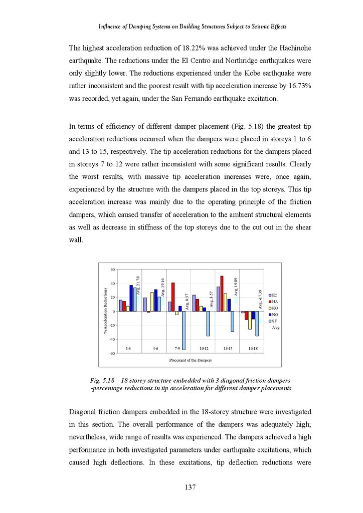
140
11.
Influence of Damping Systems on Building Structures Subject to Seismic EffectsFigure 5.21
Figure 5.22
Figure 5.23
Figure 5.24
Figure 5.25
Figure 5.26
Figure 5.27
Figure 5.28
Figure 5.29
Figure 5.30
Figure 5.31
Figure 5.32
Figure 5.33
Figure 5.34
Figure 5.35
Figure 5.36
Figure 5.37
Figure 5.38
Figure 5.39
Figure 5.40
Figure 5.41
Figure 5.42
Figure 5.43
18-Storey Structure Fitted with 1 Diagonal VE Damper – Percentage
Reductions in Tip Deflection for Different Damper Placements
18-Storey Structure Fitted with 3 Diagonal VE Dampers – Percentage
Reductions in Tip Deflection under Different Earthquake Records
18-Storey Structure Fitted with 3 Diagonal VE Dampers – Percentage
Reductions in Tip Deflection for Different Damper Placements
18-Storey Structure Fitted with 1 Diagonal VE Damper – Percentage
Reductions in Tip Acceleration under Different Earthquake Records
18-Storey Structure Fitted with 1 Diagonal VE Damper – Percentage
Reductions in Tip Acceleration for Different Damper Placements
18-Storey Structure Fitted with 3 Diagonal VE Dampers – Percentage
Reductions in Tip Acceleration under Different Earthquake Records
18-Storey Structure Fitted with 3 Diagonal VE Dampers – Percentage
Reductions in Tip Acceleration for Different Damper Placements
Tip Deflection and Acceleration Responses of the structures with Different
Placement of the Chevron Brace Friction Dampers under the El Centro
Earthquake
18-Storey Structure Fitted with 1 Chevron Brace Friction Damper –
Percentage Reductions in Tip Deflection under Different Earthquake
Records
18-Storey Structure Fitted with 1 Chevron Brace Friction Damper –
Percentage Reductions in Tip Deflection for Different Damper Placements
18-Storey Structure Fitted with 3 Chevron Brace Friction Dampers –
Percentage Reductions in Tip Deflection under Different Earthquake
Records
18-Storey Structure Fitted with 3 Chevron Brace Friction Dampers –
Percentage Reductions in Tip Deflection for Different Damper Placements
18-Storey Structure Fitted with 1 Chevron Brace Friction Damper –
Percentage Reductions in Tip Acceleration under Different Earthquake
Records
18-Storey Structure Fitted with 1 Chevron Brace Friction Damper –
Percentage Reductions in Tip Acceleration for Different Damper
Placements
18-Storey Structure Fitted with 3 Chevron Brace Friction Dampers –
Percentage Reductions in Tip Acceleration under Different Earthquake
Records
18-Storey Structure Fitted with 3 Chevron Brace Friction Dampers –
Percentage Reductions in Tip Acceleration for Different Damper
Placements
Tip Deflection and Acceleration Responses of the structures with Different
Placement of the Chevron Brace VE Dampers under the El Centro
Earthquake
18-Storey Structure Fitted with 1 Chevron Brace VE Damper – Percentage
Reductions in Tip Deflection under Different Earthquake Records
18-Storey Structure Fitted with 1 Chevron Brace VE Damper – Percentage
Reductions in Tip Deflection for Different Damper Placements
18-Storey Structure Fitted with 3 Chevron Brace VE Dampers –
Percentage Reductions in Tip Deflection under Different Earthquake
Records
18-Storey Structure Fitted with 3 Chevron Brace VE Dampers –
Percentage Reductions in Tip Deflection for Different Damper Placements
18-Storey Structure Fitted with 1 Chevron Brace VE Damper – Percentage
Reductions in Tip Acceleration under Different Earthquake Records
18-Storey Structure Fitted with 1 Chevron Brace VE Damper – Percentage
Reductions in Tip Acceleration for Different Damper Placements
ix
140
141
142
142
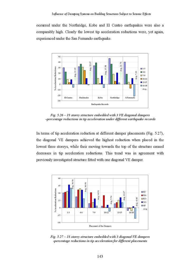
143
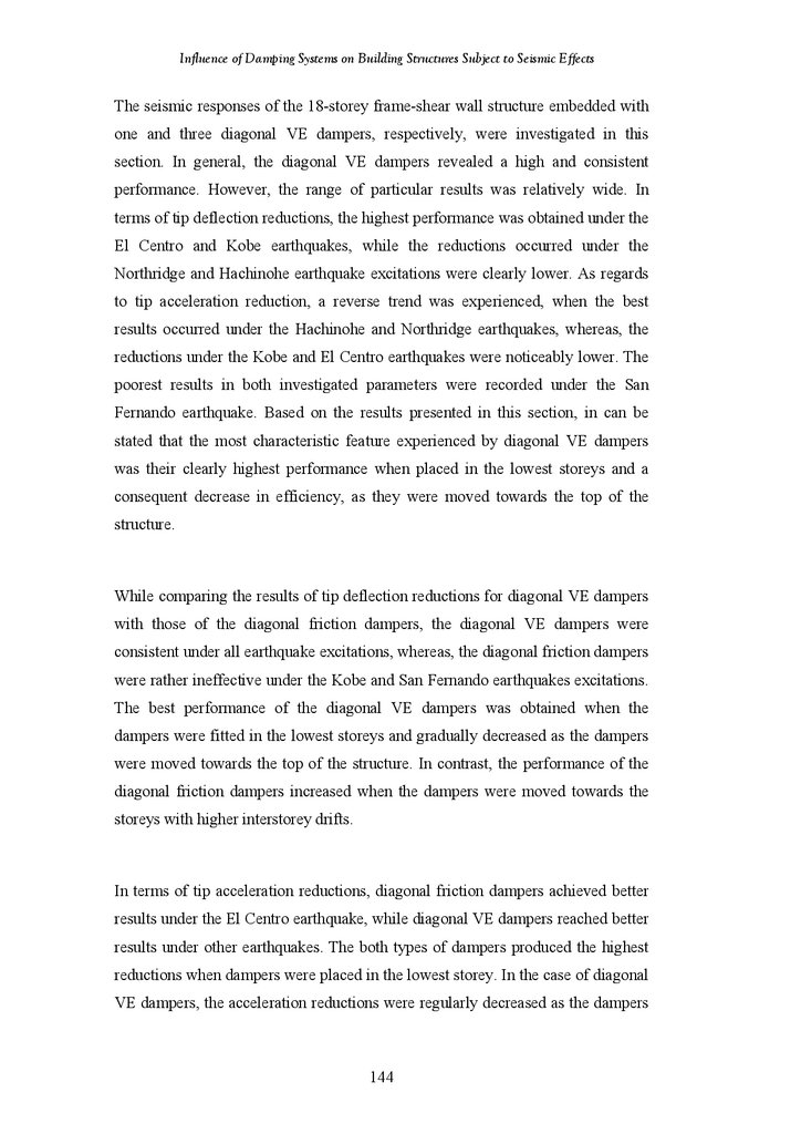
144
144
146
147
147
148
149
149
150
150
151
153
154
155
155
156
157
157
12.
Influence of Damping Systems on Building Structures Subject to Seismic EffectsFigure 5.44
Figure 5.45
Figure 5.46
Figure 5.47
Figure 5.48
Figure 5.49
Figure 5.50
Figure 5.51
Figure 5.52
Figure 5.53
Figure 5.54
Figure 5.55
Figure 5.56
Figure 5.57
Figure 5.58
Figure 5.59
Figure 5.60
Figure 5.61
Figure 5.62
Figure 5.63
Figure 5.64
Figure 5.65
18-Storey Structure Fitted with 3 Chevron Brace VE Dampers –
Percentage Reductions in Tip Acceleration under Different Earthquake
Records
18-Storey Structure Fitted with 3 Chevron Brace VE Dampers –
Percentage Reductions in Tip Acceleration for Different Damper
Placements
Tip Deflection and Acceleration Responses of the structures with Different
Placement of the Hybrid Friction-VE Dampers under the El Centro
Earthquake
18-Storey Structure Fitted with 1 Hybrid Friction-VE Damper –
Percentage Reductions in Tip Deflection under Different Earthquake
Records
18-Storey Structure Fitted with 1 Hybrid Friction-VE Damper –
Percentage Reductions in Tip Deflection for Different Damper Placements
18-Storey Structure Fitted with 3 Hybrid Friction-VE Dampers –
Percentage Reductions in Tip Deflection under Different Earthquake
Records
18-Storey Structure Fitted with 3 Hybrid Friction-VE Dampers –
Percentage Reductions in Tip Deflection for Different Damper Placements
18-Storey Structure Fitted with 1 Hybrid Friction-VE Damper –
Percentage Reductions in Tip Acceleration under Different Earthquake
Records
18-Storey Structure Fitted with 1 Hybrid Friction-VE Damper –
Percentage Reductions in Tip Acceleration for Different Damper
Placements
18-Storey Structure Fitted with 3 Hybrid Friction-VE Dampers –
Percentage Reductions in Tip Acceleration under Different Earthquake
Records
18-Storey Structure Fitted with 3 Hybrid Friction-VE Dampers –
Percentage Reductions in Tip Acceleration for Different Damper
Placements
Tip Deflection and Acceleration Responses of the structures with Different
Placement of the Lower Toggle VE Dampers under the El Centro
Earthquake
18-Storey Structure Fitted with 1 Lower Toggle VE Damper – Percentage
Reductions in Tip Deflection under Different Earthquake Records
18-Storey Structure Fitted with 1 Lower Toggle VE Damper – Percentage
Reductions in Tip Deflection for Different Damper Placements
18-Storey Structure Fitted with 3 Lower Toggle VE Dampers – Percentage
Reductions in Tip Deflection under Different Earthquake Records
18-Storey Structure Fitted with 3 Lower Toggle VE Dampers – Percentage
Reductions in Tip Deflection for Different Damper Placements
18-Storey Structure Fitted with 1 Lower Toggle VE Damper – Percentage
Reductions in Tip Acceleration under Different Earthquake Records
18-Storey Structure Fitted with 1 Lower Toggle VE Damper – Percentage
Reductions in Tip Acceleration for Different Damper Placements
18-Storey Structure Fitted with 3 Lower Toggle VE Dampers – Percentage
Reductions in Tip Acceleration under Different Earthquake Records
18-Storey Structure Fitted with 3 Lower Toggle VE Dampers – Percentage
Reductions in Tip Acceleration for Different Damper Placements
Average Percentage Tip Deflection Reductions for All Damping Systems
in All (1 Damper) Placements
Average Percentage Tip Deflection Reductions for All Damping Systems
(1 Damper Placement) under Different Earthquake Excitations
x
158
158
159
160
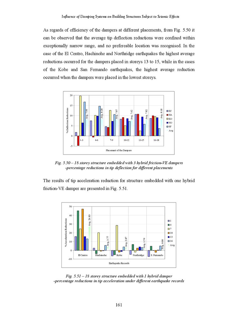
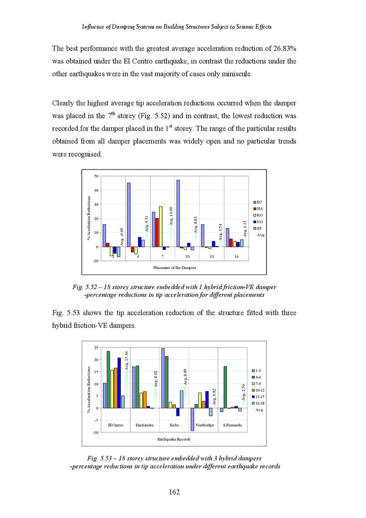
161
161
162
162
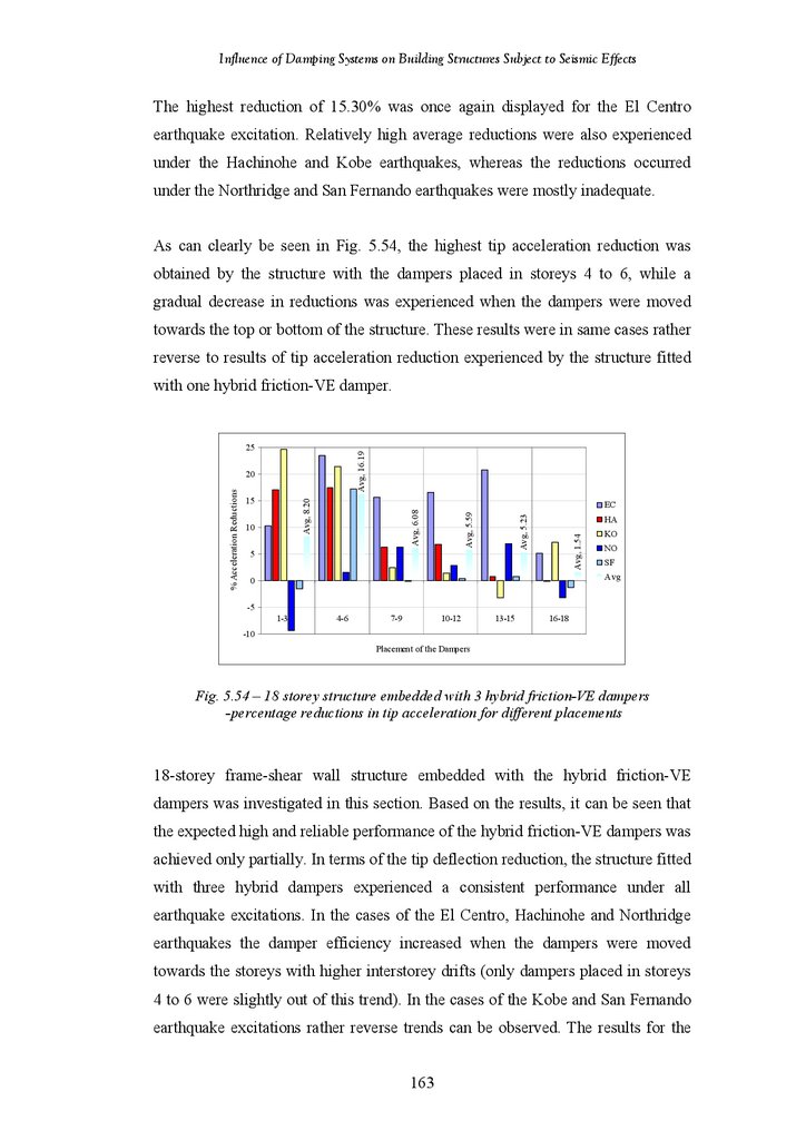
163
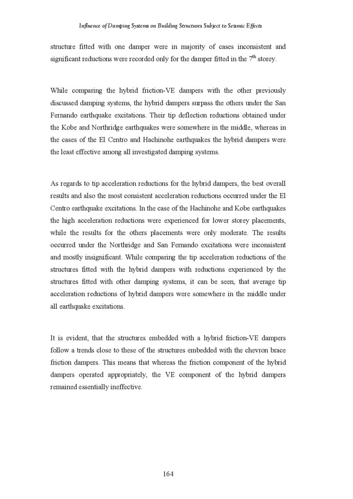
163
164
166
166
167
167
168
169
169
170
170
172
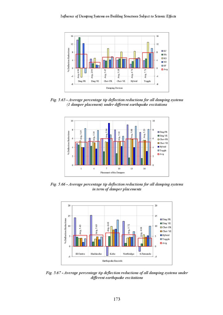
173
13.
Influence of Damping Systems on Building Structures Subject to Seismic EffectsFigure 5.66
Figure 5.67
Figure 5.68
Figure 5.69
Figure 5.70
Figure 5.71
Figure 5.72
Figure 5.73
Figure 5.74
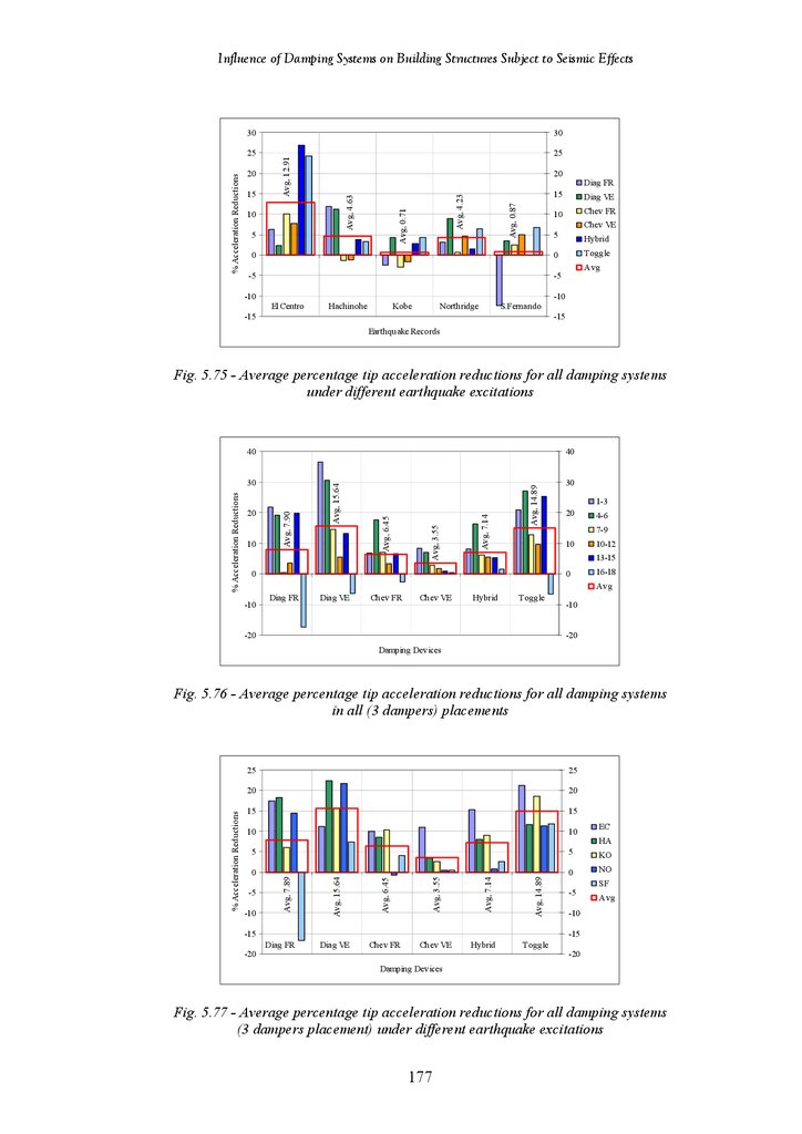
Figure 5.75
Figure 5.76
Figure 5.77
Figure 5.78
Figure 5.79
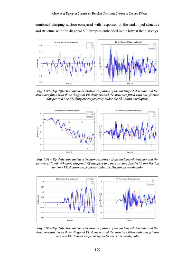
Figure 5.80
Figure 5.81
Figure 5.82
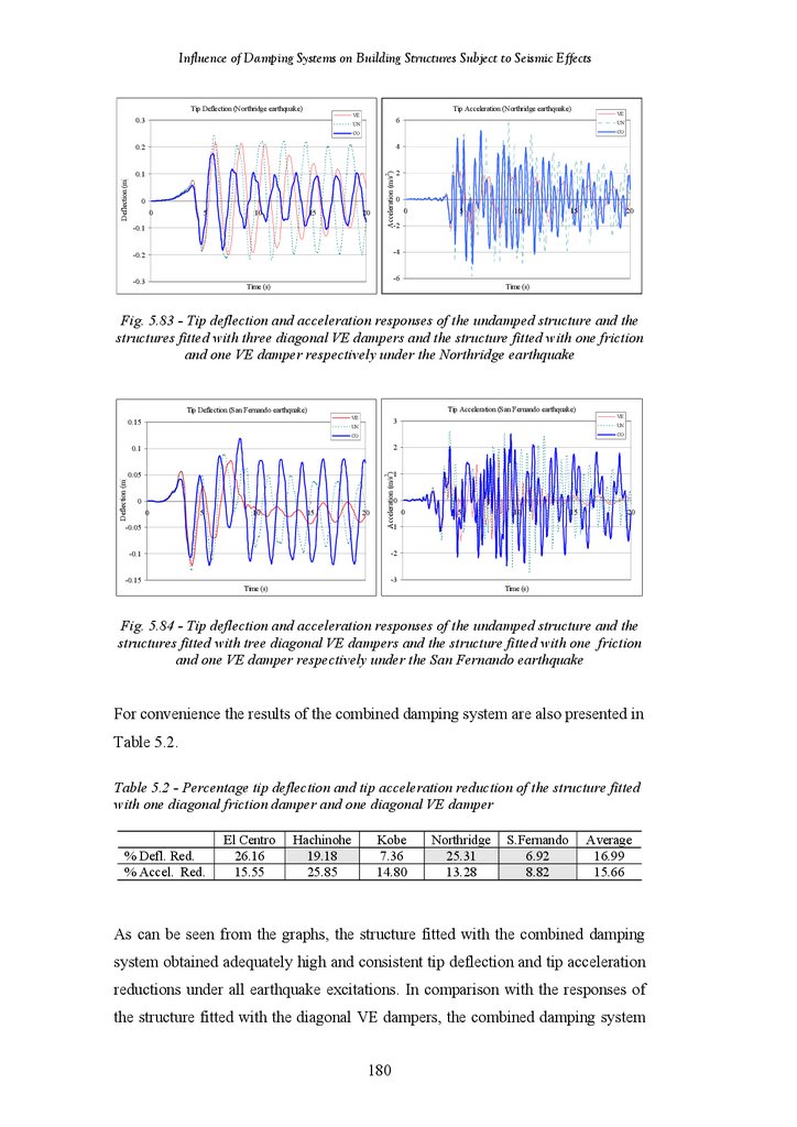
Figure 5.83
Figure 5.84
Figure 5.85
Figure 5.86
Figure 5.87
Figure 5.88
Average Percentage Tip Deflection Reductions for All Damping Systems
in Terms of Damper Placements
Average Percentage Tip Deflection Reductions of All Systems under
Different Earthquake Excitations
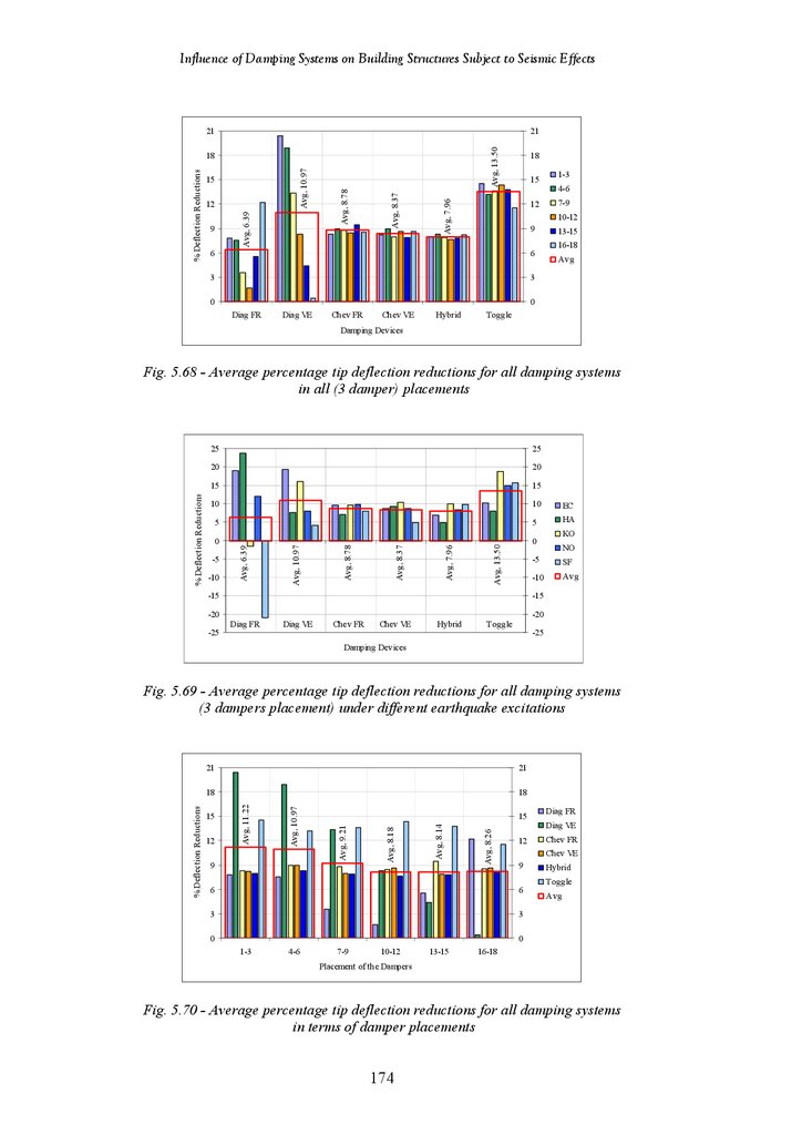
Average Percentage Tip Deflection Reductions for All Damping Systems
in All (3 Dampers) Placements
Average Percentage Tip Deflection Reductions for All Damping Systems
(3 Dampers Placement) under Different Earthquake Excitations
Average Percentage Tip Deflection Reductions for All Damping Systems
in Terms of Damper Placements
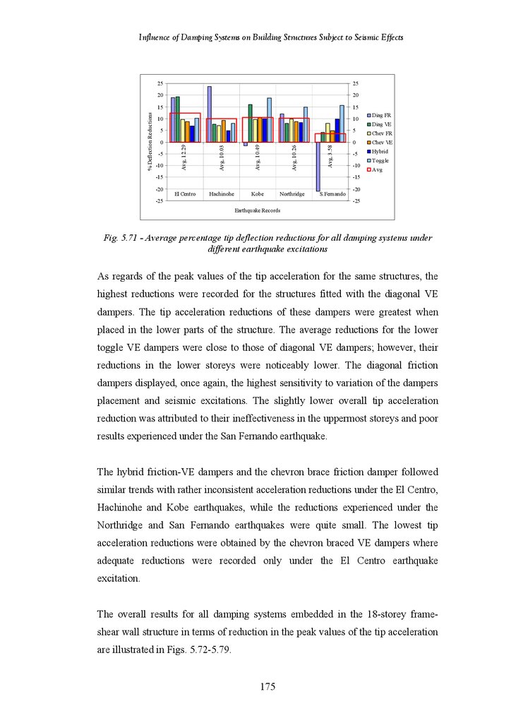
Average Percentage Tip Deflection Reductions of All Systems under
Different Earthquake Excitations
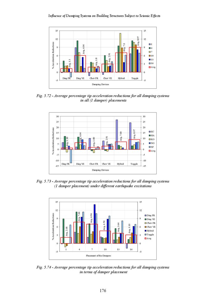
Average Percentage Tip Acceleration Reductions for All Damping
Systems in All (1 Damper) Placements
Average Percentage Tip Acceleration Reductions for All Damping
Systems (1 Damper Placement) under Different Earthquake Excitations
Average Percentage Tip Acceleration Reductions for All Damping
Systems in Terms of Damper Placements
Average Percentage Tip Acceleration Reductions of All Systems under
Different Earthquake Excitations
Average Percentage Tip Acceleration Reductions for All Damping
Systems in All (3 Dampers) Placements
Average Percentage Tip Acceleration Reductions for All Damping
Systems (3 Dampers Placement) under Different Earthquake Excitations
Average Percentage Tip Acceleration Reductions for All Damping
Systems in Terms of Damper Placements
Average Percentage Tip Acceleration Reductions of All Systems under
Different Earthquake Excitations
Tip deflection and Tip Acceleration Responses of the Undamped Structure
and the Structure Fitted with 3 Diagonal VE Dampers and Structure Fitted
with 1 Friction and 1 VE Damper under the El Centro Earthquake
Tip deflection and Tip Acceleration Responses of the Undamped Structure
and the Structure Fitted with 3 Diagonal VE Dampers and Structure Fitted
with 1 Friction and 1 VE Damper under the Hachinohe Earthquake
Tip deflection and Tip Acceleration Responses of the Undamped Structure
and the Structure Fitted with 3 Diagonal VE Dampers and Structure Fitted
with 1 Friction and 1 VE Damper under the Kobe Earthquake
Tip deflection and Tip Acceleration Responses of the Undamped Structure
and the Structure Fitted with 3 Diagonal VE Dampers and Structure Fitted
with 1 Friction and 1 VE Damper under the Northridge Earthquake
Tip deflection and Tip Acceleration Responses of the Undamped Structure
and the Structure Fitted with 3 Diagonal VE Dampers and Structure Fitted
with 1 Friction and 1 VE Damper under the San Fernando Earthquake
Tip Deflection and Acceleration Responses of Undamped Frame Structure
and Frame Structure Fitted with Diagonal VE Dampers under the El
Centro Earthquake
Tip Deflection and Acceleration Responses of Undamped Frame Structure
and Frame Structure Fitted with Diagonal VE Dampers under the
Hachinohe Earthquake
Tip Deflection and Acceleration Responses of Undamped Frame Structure
and Frame Structure Fitted with Diagonal VE Dampers under the Kobe
Earthquake
Tip Deflection and Acceleration Responses of Undamped Frame Structure
and Frame Structure Fitted with Diagonal VE Dampers under the
Northridge Earthquake
xi
174
174
174
175
175
175
176
177
177
177
178
178
178
179
179
180
180
180
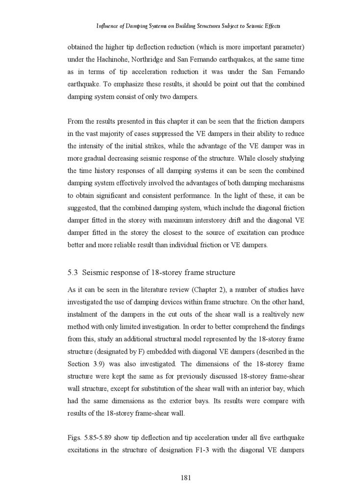
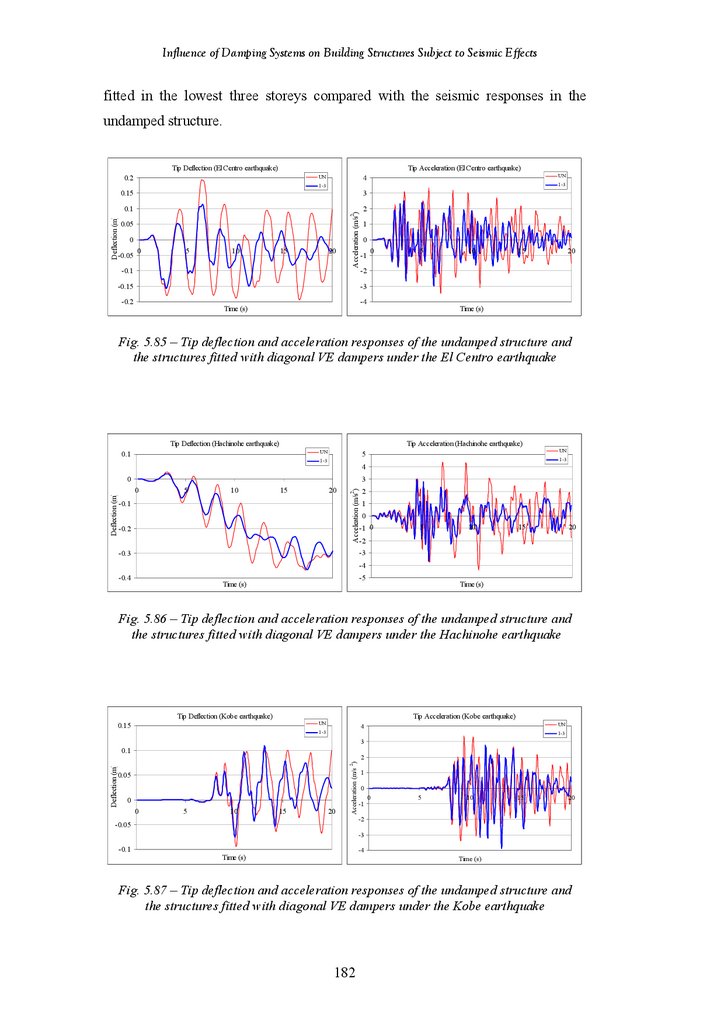
181
182
183
183
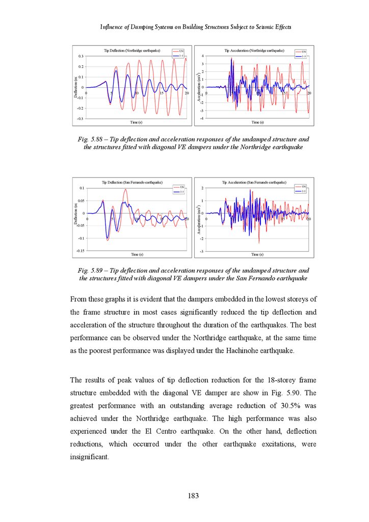
183
14.
Influence of Damping Systems on Building Structures Subject to Seismic EffectsFigure 5.89
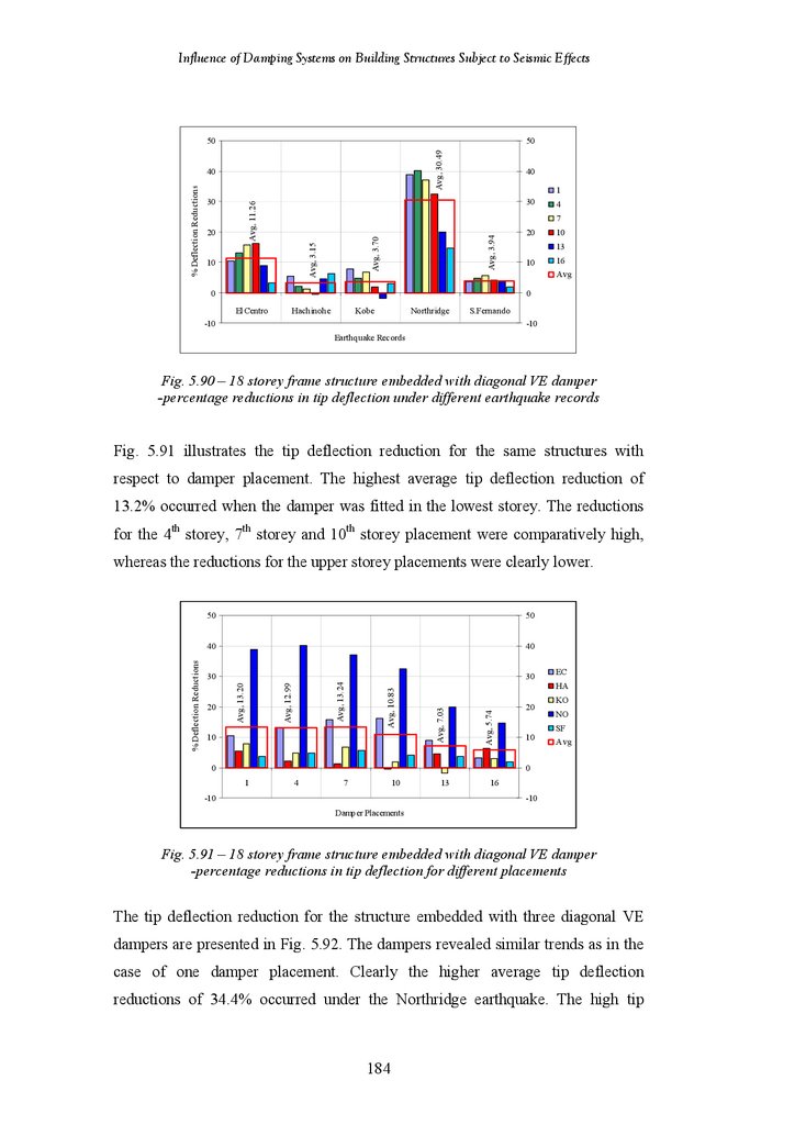
Figure 5.90
Figure 5.91
Figure 5.92
Figure 5.93
Figure 5.94
Figure 5.95
Figure 5.96
Figure 5.97
Figure 5.98
Figure 5.99
Figure 6.1
Figure 6.2
Figure 6.3
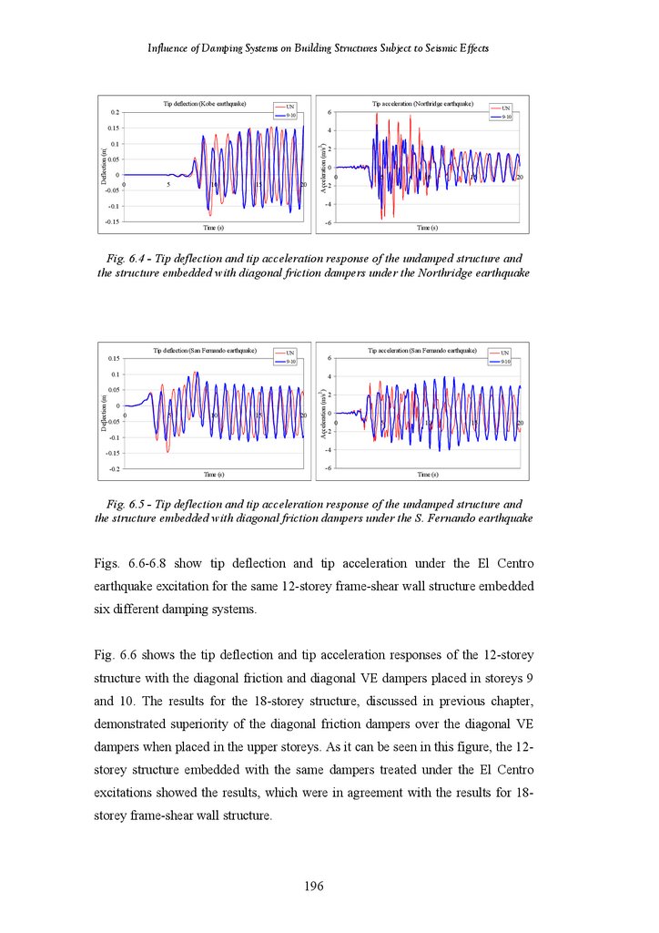
Figure 6.4
Figure 6.5
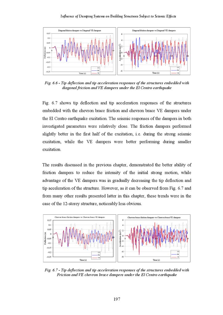
Figure 6.6
Figure 6.7
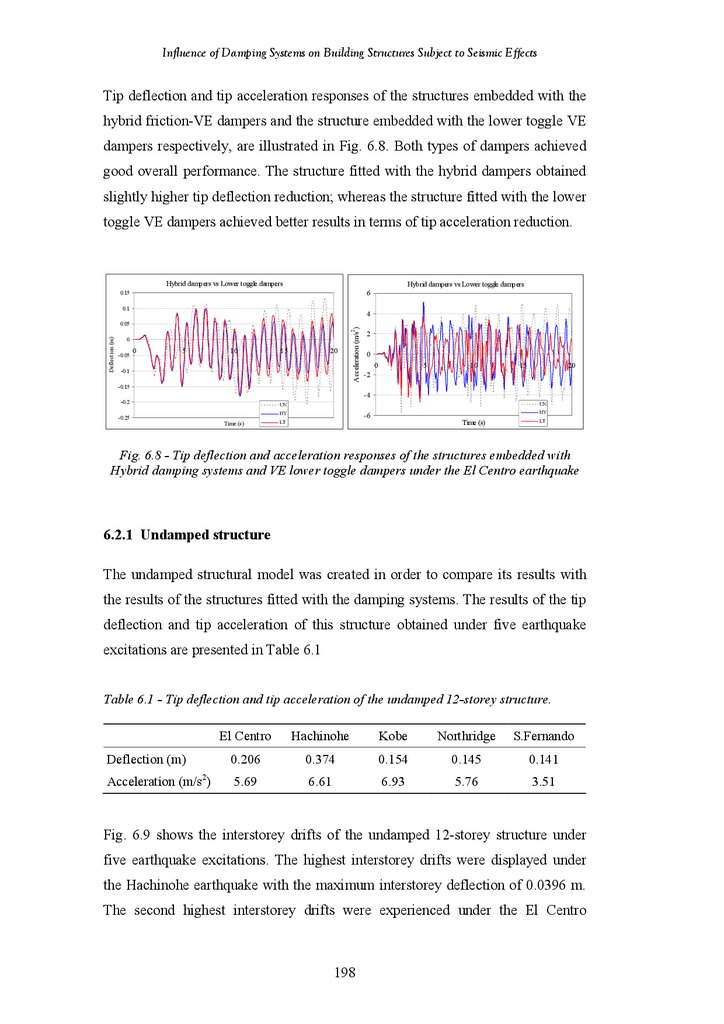
Figure 6.8
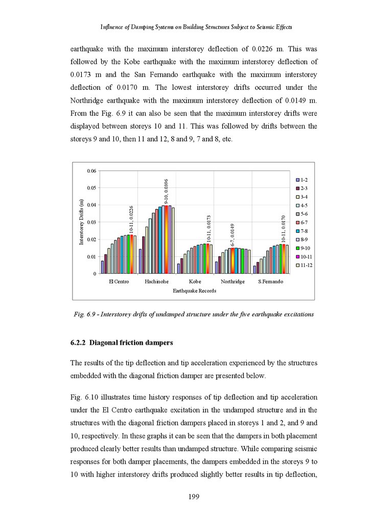
Figure 6.9
Figure 6.10
Tip Deflection and Acceleration Responses of Undamped Frame Structure
and Frame Structure Fitted with Diagonal VE Dampers under the San
Fernando Earthquake
18-Storey Frame Structure Fitted with Diagonal VE Damper – Percentage
Reduction in Tip Deflection under Different Earthquake Records
18-Storey Frame Structure Fitted with Diagonal VE Damper – Percentage
Reduction in Tip Deflection for Different Placements
18-Storey Frame Structure Fitted with 3 Diagonal VE Dampers –
Percentage Reduction in Tip Deflection under Different Earthquake
Records
18-Storey Frame Structure Fitted with 3 Diagonal VE Dampers –
Percentage Reduction in Tip Deflection for Different Placements
18-Storey Frame Structure Fitted with Diagonal VE Damper – Percentage
Reduction in Tip Acceleration under Different Earthquake Records
18-Storey Frame Structure Fitted with Diagonal VE Damper – Percentage
Reduction in Tip Acceleration for Different Placements
18-Storey Frame Structure Fitted with 3 Diagonal VE Dampers –
Percentage Reduction in Tip Acceleration under Different Earthquake
Records
18-Storey Frame Structure Fitted with 3 Diagonal VE Dampers –
Percentage Reduction in Tip Acceleration for Different Placements
18-Storey Frame-Shear Wall Structure vs. 18-Storey Frame Structure –
Percentage Reductions in Tip Deflection under Different Earthquake
Records
18-Storey Frame-Shear Wall Structure vs. 18-Storey Frame Structure –
Percentage Reductions in Tip Acceleration under Different Earthquake
Records
184
Tip Deflection and Acceleration Response of Undamped Structure and
Structure Fitted with Diagonal Friction Damper under the El Centro
Earthquake
Tip Deflection and Acceleration Response of Undamped Structure and
Structure Fitted with Diagonal Friction Damper under the Hachinohe
Earthquake
Tip Deflection and Acceleration Response of Undamped Structure and
Structure Fitted with Diagonal Friction Damper under the Kobe
Earthquake
Tip Deflection and Acceleration Response of Undamped Structure and
Structure Fitted with Diagonal Friction Damper under the Northridge
Earthquake
Tip Deflection and Acceleration Response of Undamped Structure and
Structure Fitted with Diagonal Friction Damper under the San Fernando
Earthquake
Tip Deflection and Acceleration Response of Structures fitted with
Diagonal Friction and VE Dampers under the El Centro Earthquake
Tip Deflection and Acceleration Response of Structures fitted with
Chevron Brace Friction and VE Dampers under the El Centro Earthquake
Tip Deflection and Acceleration Response of Structures fitted with Hybrid
Friction-VE Damper and Lower Toggle VE Dampers under the El Centro
Earthquake
Interstorey Drifts of Undamped Structure under Five Earthquake
Excitations
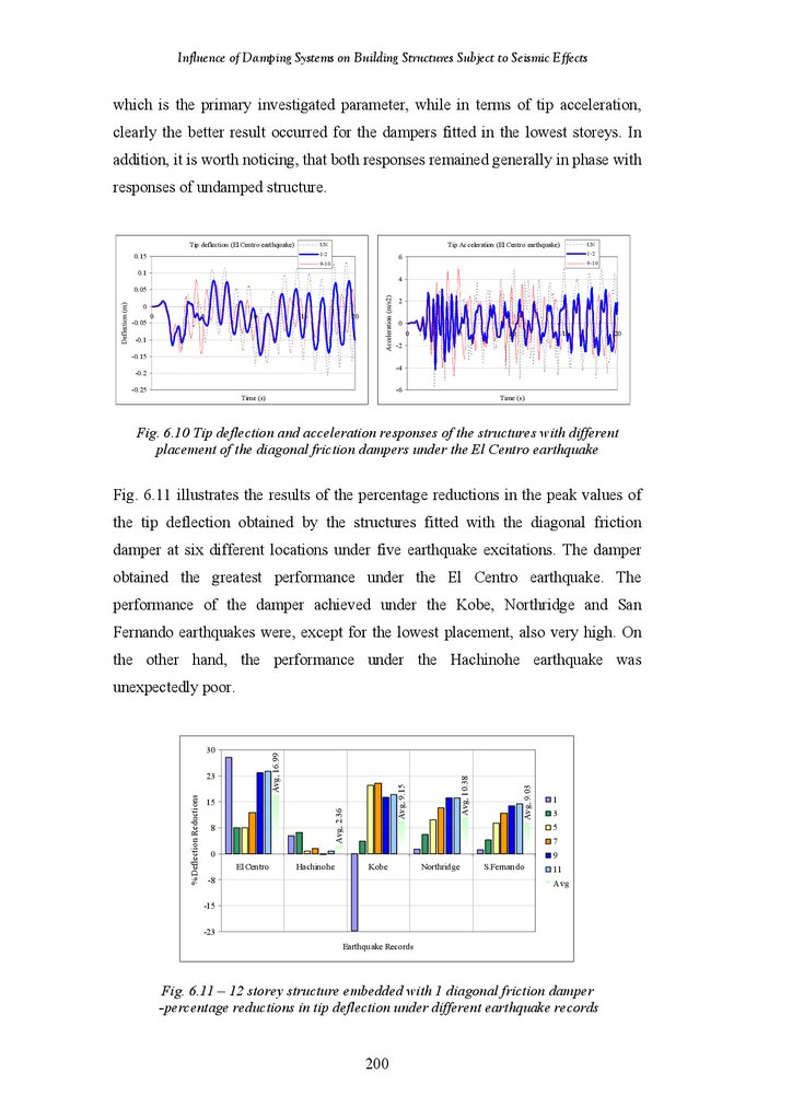
Tip Deflection and Acceleration Response of the structures with Different
Placement of the Diagonal Friction Dampers under the El Centro
Earthquake
196
xii
185
185
186
186
187
187
188
188
190
191
196
196
197
197
198
198
199
200
201
15.
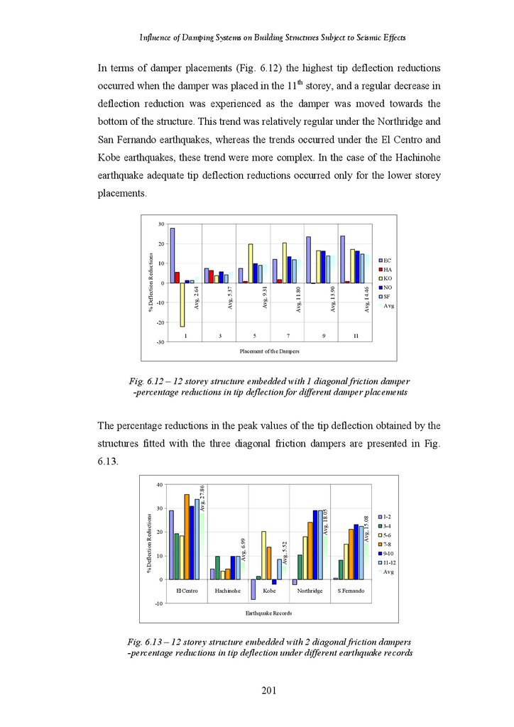
Influence of Damping Systems on Building Structures Subject to Seismic EffectsFigure 6.11
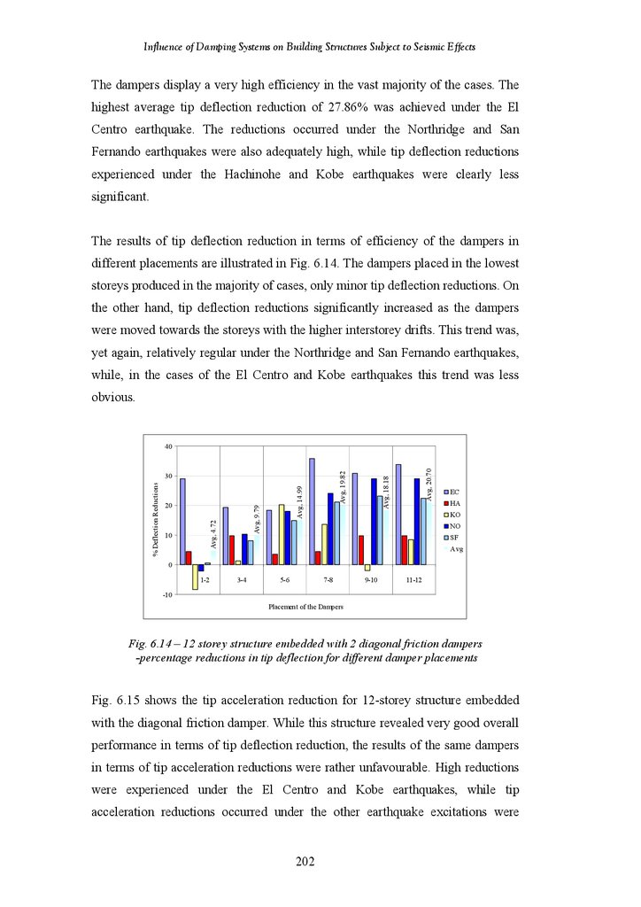
Figure 6.12
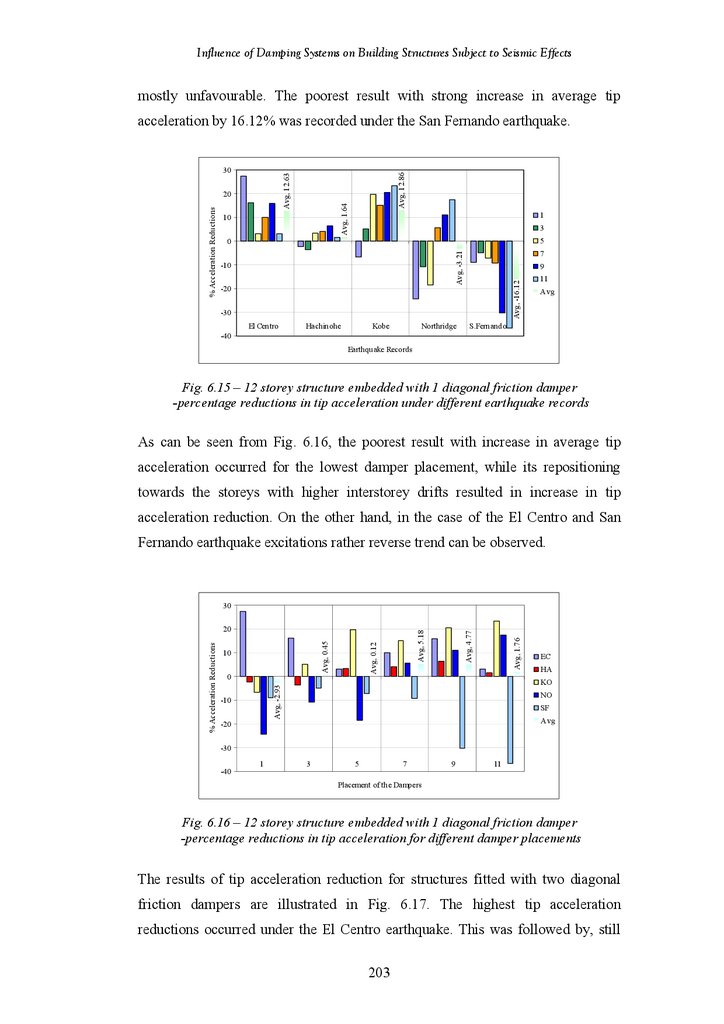
Figure 6.13
Figure 6.14
Figure 6.15
Figure 6.16
Figure 6.17
Figure 6.18
Figure 6.19
Figure 6.20
Figure 6.21
Figure 6.22
Figure 6.23
Figure 6.24
Figure 6.25
Figure 6.26
Figure 6.27
Figure 6.28
Figure 6.29
Figure 6.30
Figure 6.31
Figure 6.32
Figure 6.33
Figure 6.34
12-Storey Structure Fitted with 1 Diagonal Friction Damper – Percentage
Reductions in Tip Deflection under Different Earthquake Records
12-Storey Structure Fitted with 1 Diagonal Friction Damper – Percentage
Reductions in Tip Deflection for Different Damper Placements
12-Storey Structure Fitted with 2 Diagonal Friction Dampers – Percentage
Reductions in Tip Deflection under Different Earthquake Records
12-Storey Structure Fitted with 2 Diagonal Friction Dampers – Percentage
Reductions in Tip Deflection for Different Damper Placements
12-Storey Structure Fitted with 1 Diagonal Friction Damper – Percentage
Reductions in Tip Acceleration under Different Earthquake Records
12-Storey Structure Fitted with 1 Diagonal Friction Damper – Percentage
Reductions in Tip Acceleration for Different Damper Placements
12-Storey Structure Fitted with 2 Diagonal Friction Dampers – Percentage
Reductions in Tip Acceleration under Different Earthquake Records
12-Storey Structure Fitted with 2 Diagonal Friction Dampers – Percentage
Reductions in Tip Acceleration for Different Damper Placements
Tip Deflection and Acceleration Responses of the structures with Different
Placement of the Diagonal VE Dampers under the El Centro Earthquake
12-Storey Structure Fitted with 1 Diagonal VE Damper – Percentage
Reductions in Tip Deflection under Different Earthquake Records
12-Storey Structure Fitted with 1 Diagonal VE Damper – Percentage
Reductions in Tip Deflection for Different Damper Placements
12-Storey Structure Fitted with 2 Diagonal VE Dampers – Percentage
Reductions in Tip Deflection under Different Earthquake Records
12-Storey Structure Fitted with 2 Diagonal VE Dampers – Percentage
Reductions in Tip Deflection for Different Damper Placements
12-Storey Structure Fitted with 1 Diagonal VE Damper – Percentage
Reductions in Tip Acceleration under Different Earthquake Records
12-Storey Structure Fitted with 1 Diagonal VE Damper – Percentage
Reductions in Tip Acceleration for Different Damper Placements
12-Storey Structure Fitted with 2 Diagonal VE Dampers – Percentage
Reductions in Tip Acceleration under Different Earthquake Records
12-Storey Structure Fitted with 2 Diagonal VE Dampers – Percentage
Reductions in Tip Acceleration for Different Damper Placements
Tip Deflection and Acceleration Responses of the structures with Different
Placement of the Chevron Brace Friction Dampers under the El Centro
Earthquake
12-Storey Structure Fitted with 1 Chevron Brace Friction Damper –
Percentage Reductions in Tip Deflection under Different Earthquake
Records
12-Storey Structure Fitted with 1 Chevron Brace Friction Damper –
Percentage Reductions in Tip Deflection for Different Damper Placements
12-Storey Structure Fitted with 2 Chevron Brace Friction Dampers –
Percentage Reductions in Tip Deflection under Different Earthquake
Records
12-Storey Structure Fitted with 2 Chevron Brace Friction Dampers –
Percentage Reductions in Tip Deflection for Different Damper Placements
12-Storey Structure Fitted with 1 Chevron Brace Friction Damper –
Percentage Reductions in Tip Acceleration under Different Earthquake
Records
12-Storey Structure Fitted with 1 Chevron Brace Friction Damper –
Percentage Reductions in Tip Acceleration for Different Damper
Placements
xiii
201
202
203
203
204
204
204
205
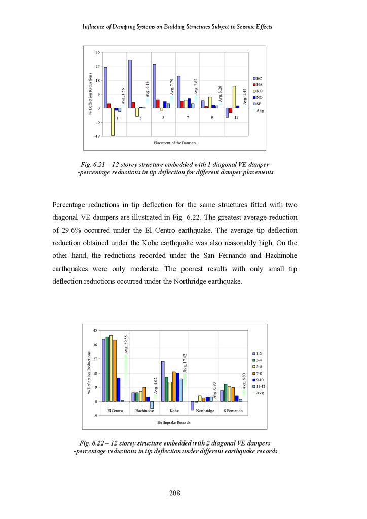
208
208
209
209
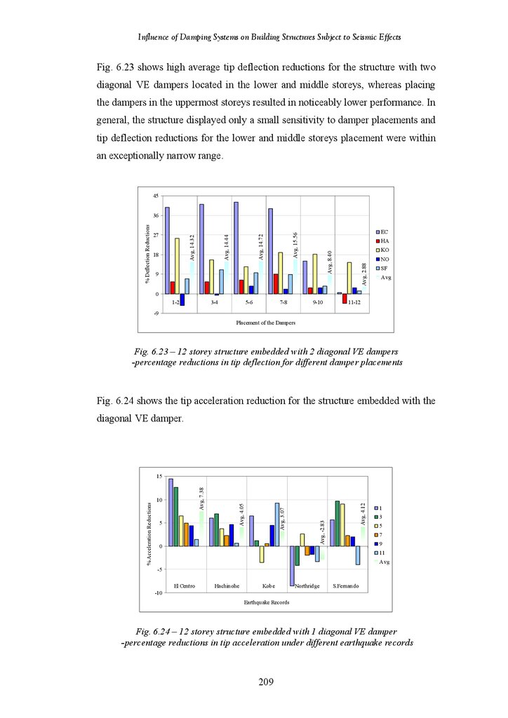
210
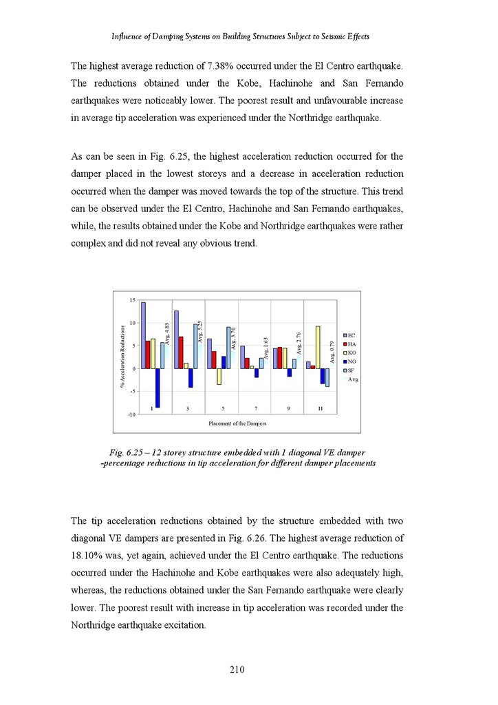
210
211
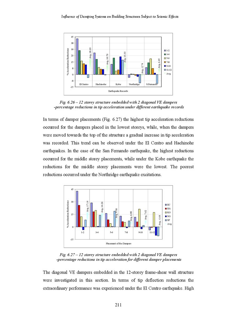
212
212
214
215
215
216
216
217
218
16.
Influence of Damping Systems on Building Structures Subject to Seismic EffectsFigure 6.35
Figure 6.36
Figure 6.37
Figure 6.38
Figure 6.39
Figure.6.40
Figure 6.41
Figure 6.42
Figure 6.43
Figure 6.44
Figure 6.45
Figure 6.46
Figure 6.47
Figure 6.48
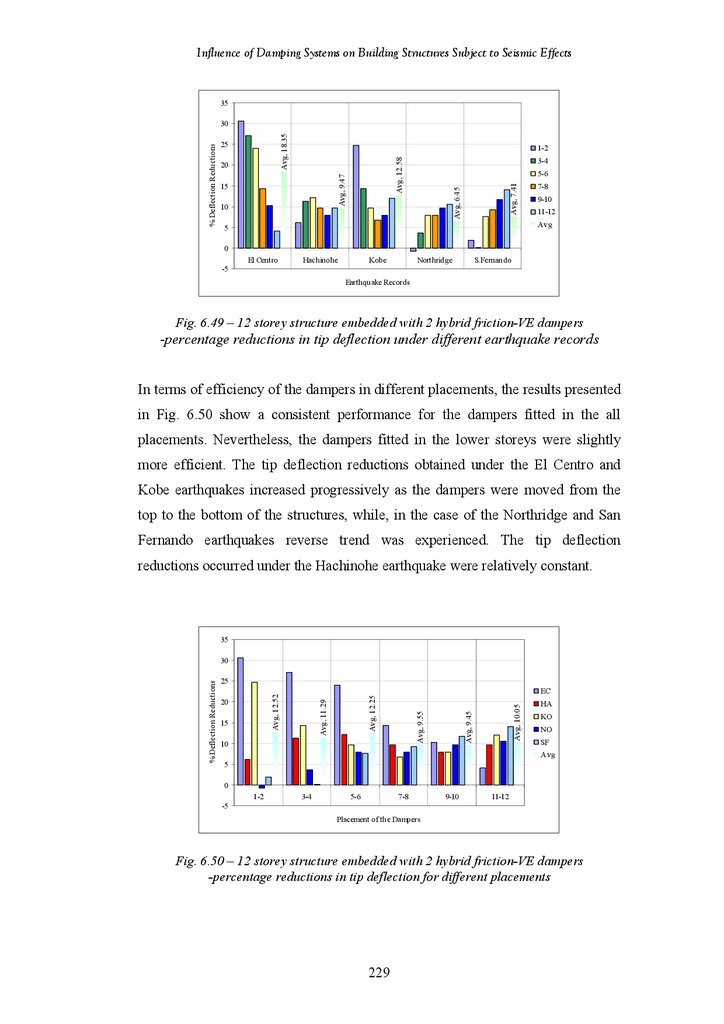
Figure 6.49
Figure 6.50
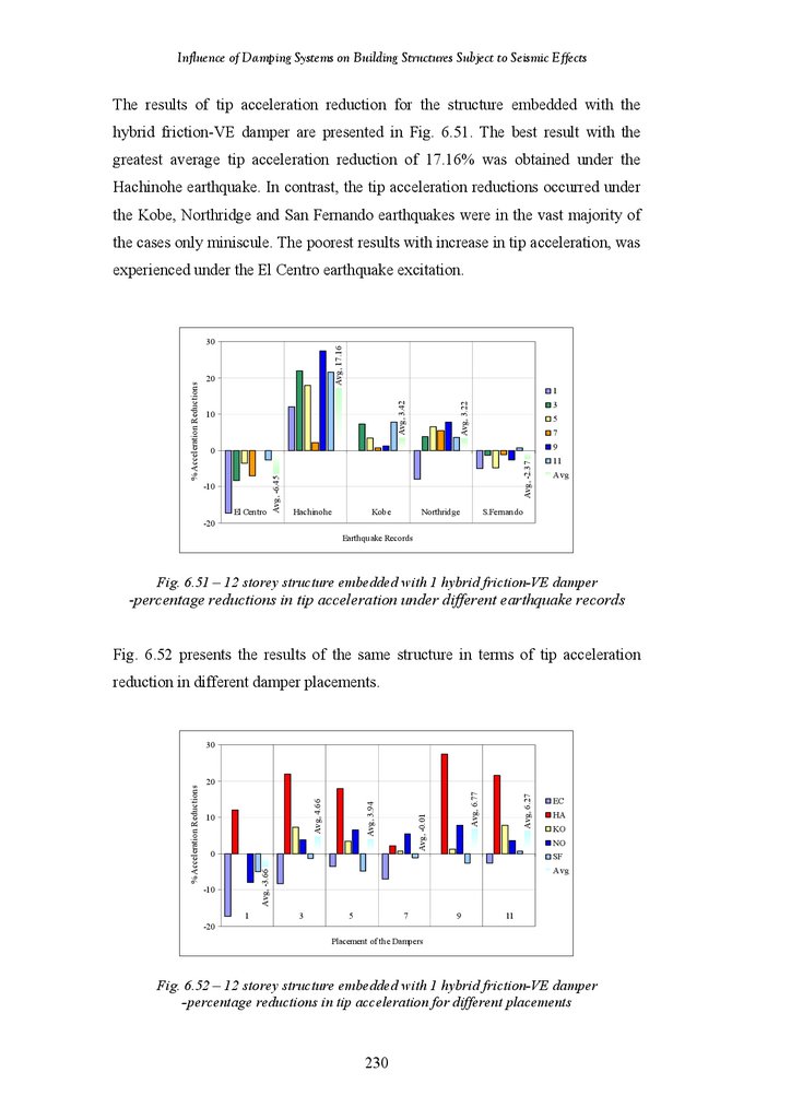
Figure 6.51
Figure 6.52
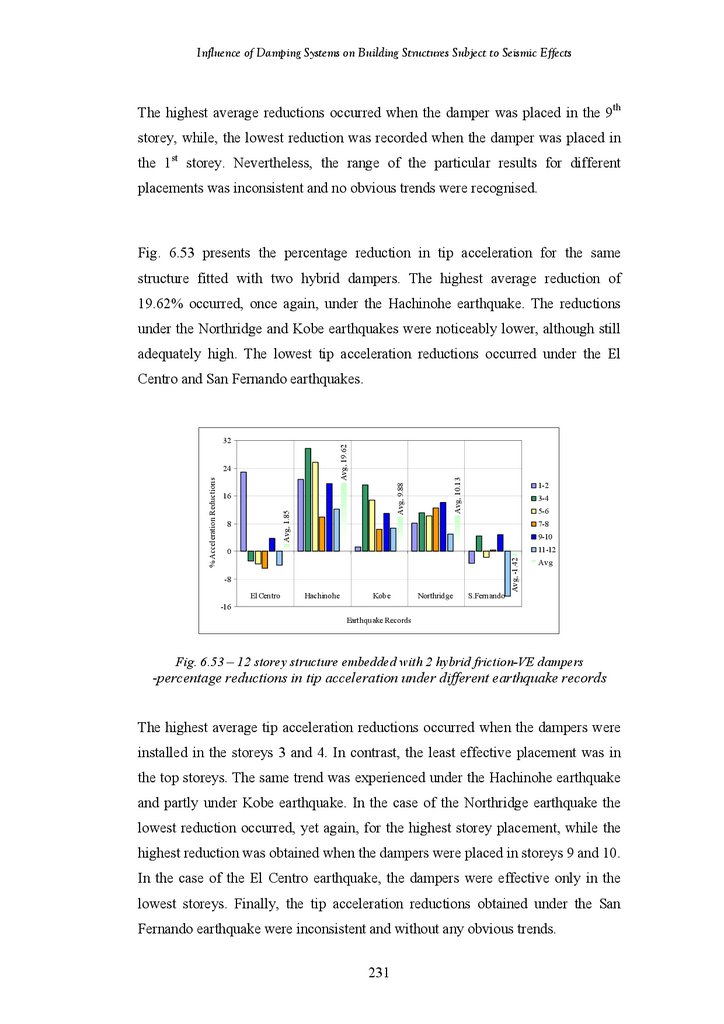
Figure 6.53
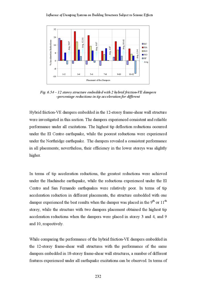
Figure 6.54
12-Storey Structure Fitted with 2 Chevron Brace Friction Dampers –
Percentage Reductions in Tip Acceleration under Different Earthquake
Records
12-Storey Structure Fitted with 2 Chevron Brace Friction Dampers –
Percentage Reductions in Tip Acceleration for Different Damper
Placements
Tip Deflection and Acceleration Responses of the structures with Different
Placement of the Chevron Brace VE Dampers under the El Centro
Earthquake
12-Storey Structure Fitted with 1 Chevron Brace VE Damper – Percentage
Reductions in Tip Deflection under Different Earthquake Records
12-Storey Structure Fitted with 1 Chevron Brace VE Damper – Percentage
Reductions in Tip Deflection for Different Damper Placements
12-Storey Structure Fitted with 2 Chevron Brace VE Dampers –
Percentage Reductions in Tip Deflection under Different Earthquake
Records
12-Storey Structure Fitted with 2 Chevron Brace VE Dampers –
Percentage Reductions in Tip Deflection for Different Damper Placements
12-Storey Structure Fitted with 1 Chevron Brace VE Damper – Percentage
Reductions in Tip Acceleration under Different Earthquake Records
12-Storey Structure Fitted with 1 Chevron Brace VE Damper – Percentage
Reductions in Tip Acceleration for Different Damper Placements
12-Storey Structure Fitted with 2 Chevron Brace VE Dampers –
Percentage Reductions in Tip Acceleration under Different Earthquake
Records
12-Storey Structure Fitted with 2 Chevron Brace VE Dampers –
Percentage Reductions in Tip Acceleration for Different Damper
Placements
Tip Deflection and Acceleration Responses of the structures with Different
Placement of the Hybrid Friction-VE Dampers under the El Centro
Earthquake
12-Storey Structure Fitted with 1 Hybrid Friction-VE Damper –
Percentage Reductions in Tip Deflection under Different Earthquake
Records
12-Storey Structure Fitted with 1 Hybrid Friction-VE Damper –
Percentage Reductions in Tip Deflection for Different Damper Placements
12-Storey Structure Fitted with 2 Hybrid Friction-VE Dampers –
Percentage Reductions in Tip Deflection under Different Earthquake
Records
12-Storey Structure Fitted with 2 Hybrid Friction-VE Dampers –
Percentage Reductions in Tip Deflection for Different Damper Placements
12-Storey Structure Fitted with 1 Hybrid Friction-VE Damper –
Percentage Reductions in Tip Acceleration under Different Earthquake
Records
12-Storey Structure Fitted with 1 Hybrid Friction-VE Damper –
Percentage Reductions in Tip Acceleration for Different Damper
Placements
12-Storey Structure Fitted with 2 Hybrid Friction-VE Dampers –
Percentage Reductions in Tip Acceleration under Different Earthquake
Records
12-Storey Structure Fitted with 2 Hybrid Friction-VE Dampers –
Percentage Reductions in Tip Acceleration for Different Damper
Placements
xiv
218
221
221
222
222
223
223
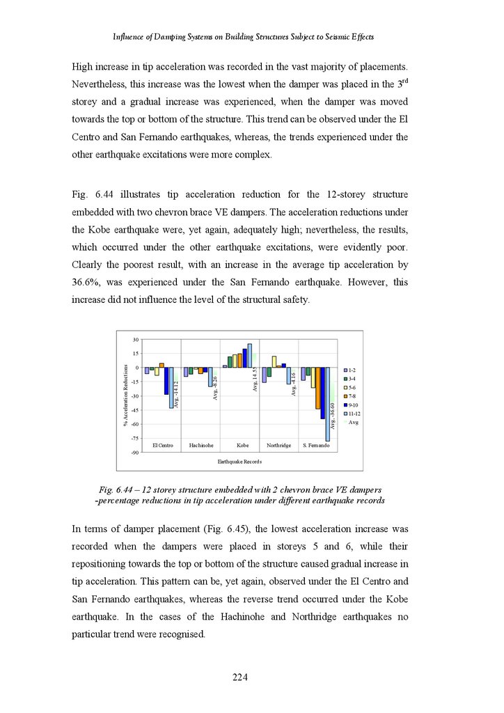
224
224
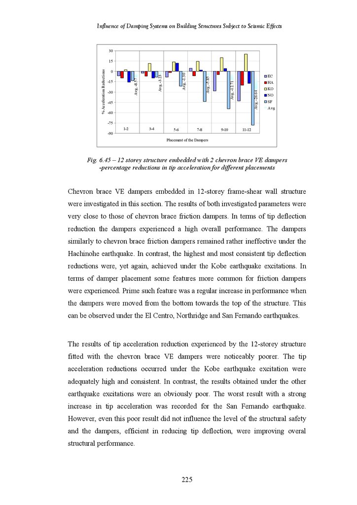
225
226
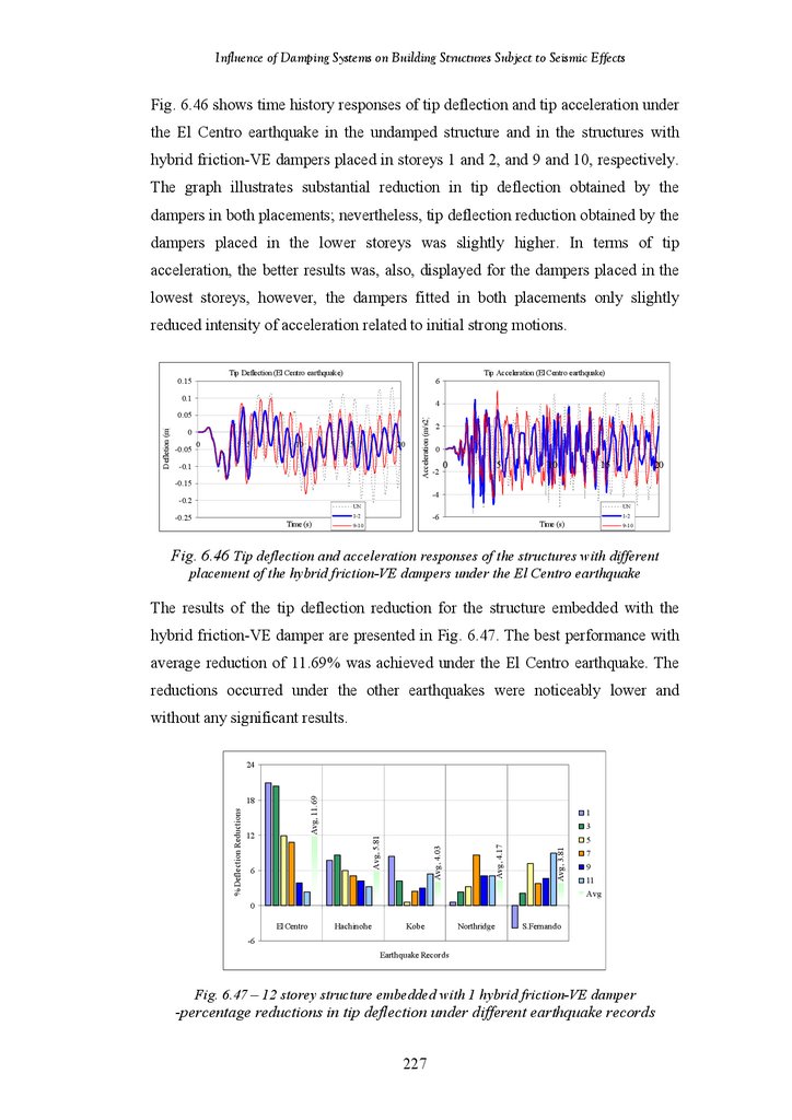
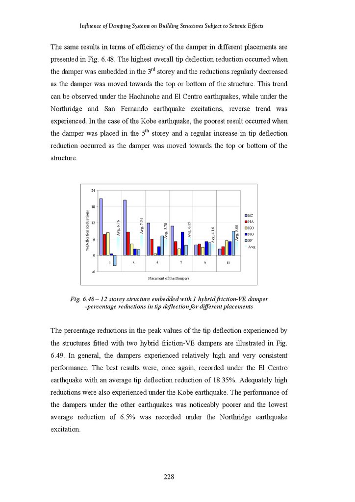
228
228
229
230
230
231
231
232
233
17.
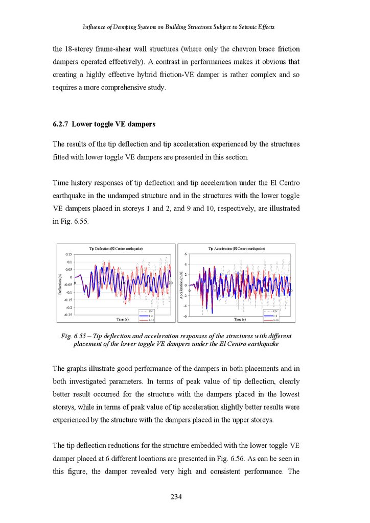
Influence of Damping Systems on Building Structures Subject to Seismic EffectsFigure 6.55
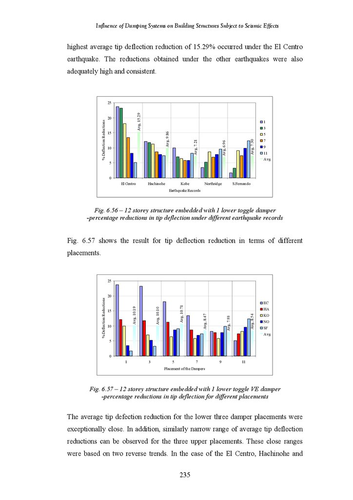
Figure 6.56
Figure 6.57
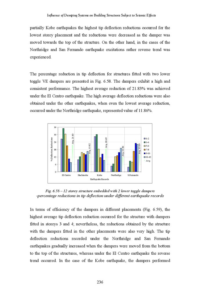
Figure 6.58
Figure 6.59
Figure 6.60
Figure 6.61
Figure 6.62
Figure 6.63
Figure 6.64
Figure 6.65
Figure 6.66
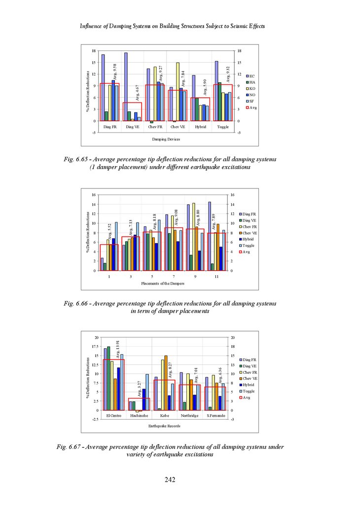
Figure 6.67
Figure 6.68
Figure 6.69
Figure 6.70
Figure 6.71
Figure 6.72
Figure 6.73
Figure 6.74
Figure 6.75
Figure 6.76
Figure 6.77
Figure 6.78
Figure 6.79
Figure 6.80
Tip Deflection and Acceleration Responses of the structures with Different
Placement of the Lower Toggle VE Dampers under the El Centro
Earthquake
12-Storey Structure Fitted with 1 Lower Toggle VE Damper – Percentage
Reductions in Tip Deflection under Different Earthquake Records
12-Storey Structure Fitted with 1 Lower Toggle VE Damper – Percentage
Reductions in Tip Deflection for Different Damper Placements
12-Storey Structure Fitted with 2 Lower Toggle VE Dampers – Percentage
Reductions in Tip Deflection under Different Earthquake Records
12-Storey Structure Fitted with 2 Lower Toggle VE Dampers – Percentage
Reductions in Tip Deflection for Different Damper Placements
12-Storey Structure Fitted with 1 Lower Toggle VE Damper – Percentage
Reductions in Tip Acceleration under Different Earthquake Records
12-Storey Structure Fitted with 1 Lower Toggle VE Damper – Percentage
Reductions in Tip Acceleration for Different Damper Placements
12-Storey Structure Fitted with 2 Lower Toggle VE Dampers – Percentage
Reductions in Tip Acceleration under Different Earthquake Records
12-Storey Structure Fitted with 2 Lower Toggle VE Dampers – Percentage
Reductions in Tip Acceleration for Different Damper Placements
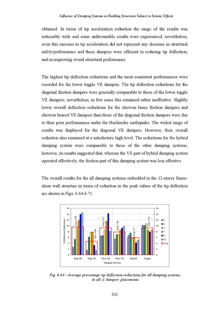
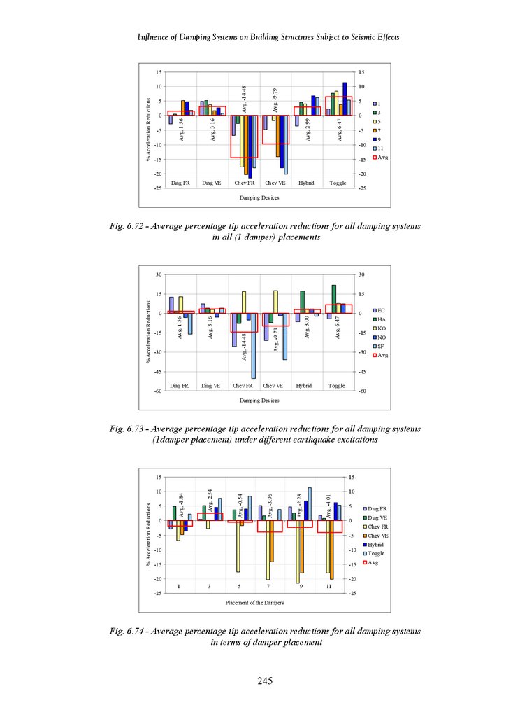
Average Percentage Tip Deflection Reductions for All Damping Systems
in All (1 Damper) Placements
Average Percentage Tip Deflection Reductions for All Damping Systems
(1 Damper Placement) under Different Earthquake Excitations
Average Percentage Tip Deflection Reductions for All Damping Systems
in Terms of Damper Placements
Average Percentage Tip Deflection Reductions of All Systems under
Different Earthquake Excitations
Average Percentage Tip Deflection Reductions for All Damping Systems
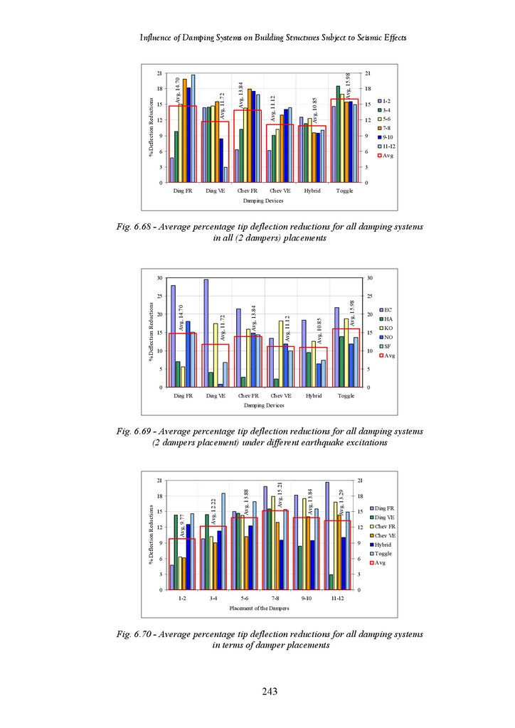
in All (2 Dampers) Placements
Average Percentage Tip Deflection Reductions for All Damping Systems
(2 Dampers Placement) under Different Earthquake Excitations
Average Percentage Tip Deflection Reductions for All Damping Systems
in Terms of Damper Placements
Average Percentage Tip Deflection Reductions of All Systems under
Different Earthquake Excitations
Average Percentage Tip Acceleration Reductions for All Damping
Systems in All (1 Damper) Placements
Average Percentage Tip Acceleration Reductions for All Damping
Systems (1 Damper Placement) under Different Earthquake Excitations
Average Percentage Tip Acceleration Reductions for All Damping
Systems in Terms of Damper Placements
Average Percentage Tip Acceleration Reductions of All Systems under
Different Earthquake Excitations
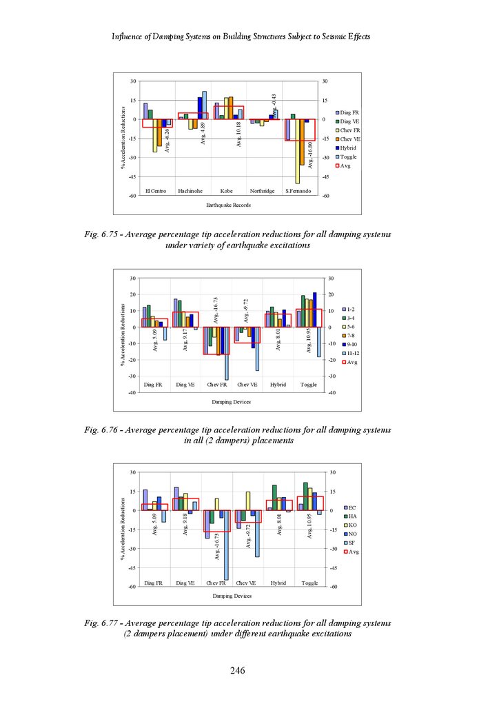
Average Percentage Tip Acceleration Reductions for All Damping
Systems in All (2 Dampers) Placements
Average Percentage Tip Acceleration Reductions for All Damping
Systems (2 Dampers Placement) under Different Earthquake Excitations
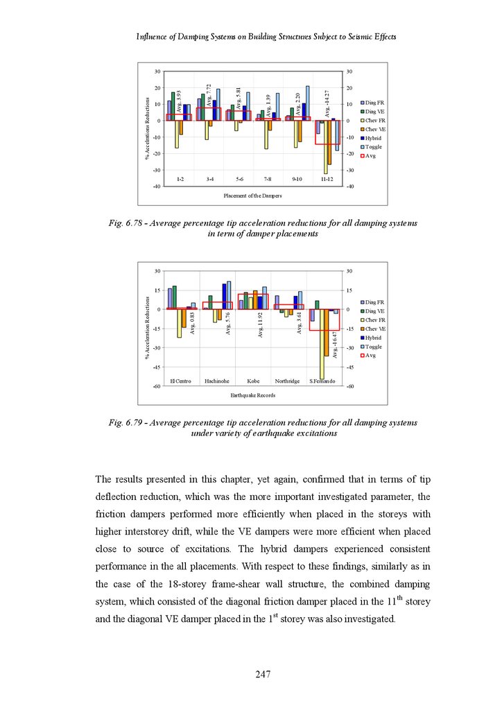
Average Percentage Tip Acceleration Reductions for All Damping
Systems in Terms of Damper Placements
Average Percentage Tip Acceleration Reductions of All Systems under
Different Earthquake Excitations
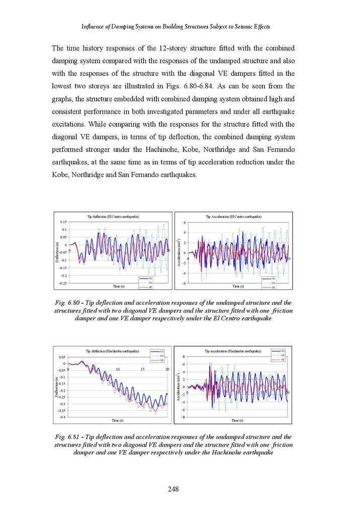
Tip deflection and Tip Acceleration Responses of the Undamped Structure
and the Structure Fitted with 2 Diagonal VE Dampers and Structure Fitted
with 1 Friction and 1 VE Damper under the El Centro Earthquake
xv
235
236
237
237
238
239
239
240
240
241
241
241
242
242
242
243
243
244
245
245
245
246
246
246
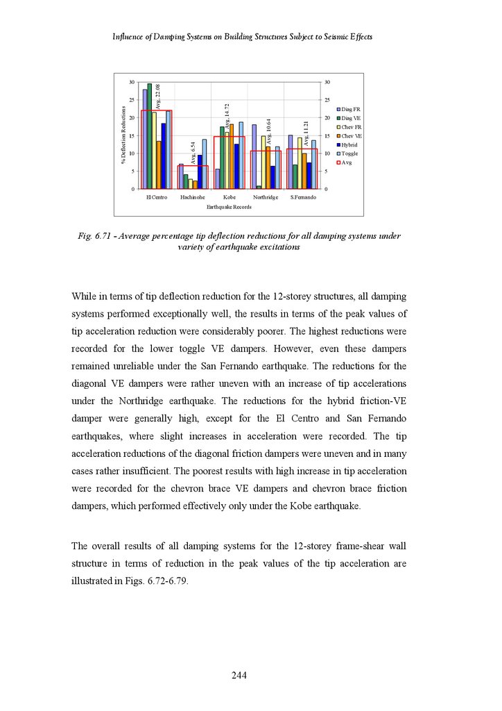
247
248
18.
Influence of Damping Systems on Building Structures Subject to Seismic EffectsFigure 6.81
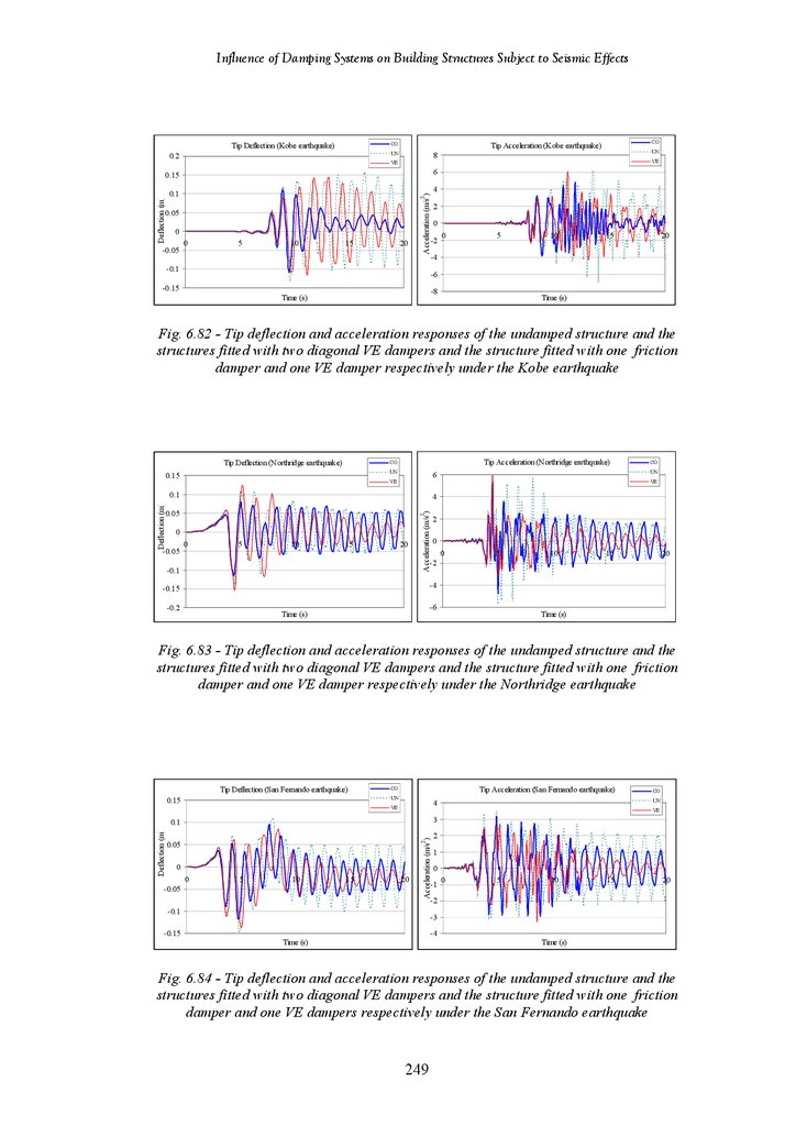
Figure 6.82
Figure 6.83
Figure 6.84
Tip deflection and Tip Acceleration Responses of the Undamped Structure
and the Structure Fitted with 2 Diagonal VE Dampers and Structure Fitted
with 1 Friction and 1 VE Damper under the Hachinohe Earthquake
Tip deflection and Tip Acceleration Responses of the Undamped Structure
and the Structure Fitted with 2 Diagonal VE Dampers and Structure Fitted
with 1 Friction and 1 VE Damper under the Kobe Earthquake
Tip deflection and Tip Acceleration Responses of the Undamped Structure
and the Structure Fitted with 3 Diagonal VE Dampers and Structure Fitted
with 1 Friction and 1 VE Damper under the Northridge Earthquake
Tip deflection and Tip Acceleration Responses of the Undamped Structure
and the Structure Fitted with 3 Diagonal VE Dampers and Structure Fitted
with 1 Friction and 1 VE Damper under the San Fernando Earthquake
249
249
249
250
Tables
Table 2.1
Table 3.1
Table 3.2
Table 3.3
Table 3.4
Table 4.1
Table 4.2
Table 4.3
Table 4.4
Table 4.5
Table 4.6
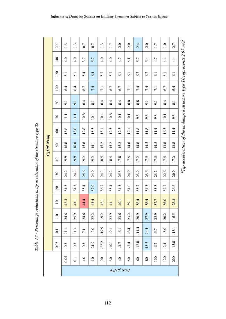
Table 4.7
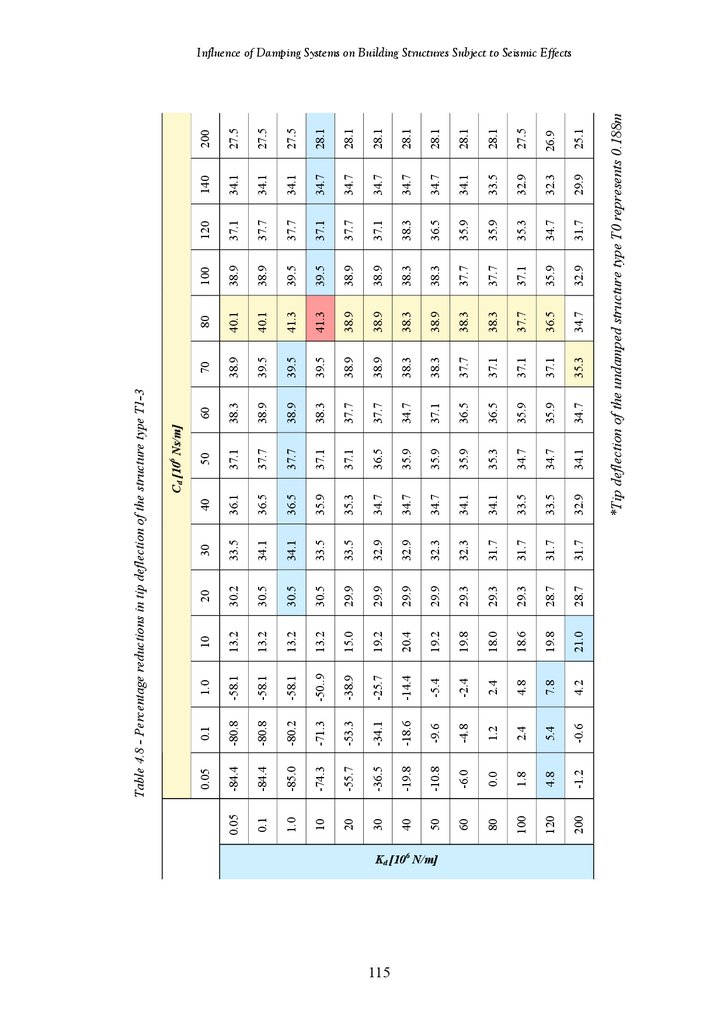
Table 4.8
Table 4.9
Table 5.1
Table 5.2
Table 6.1
Table 6.2
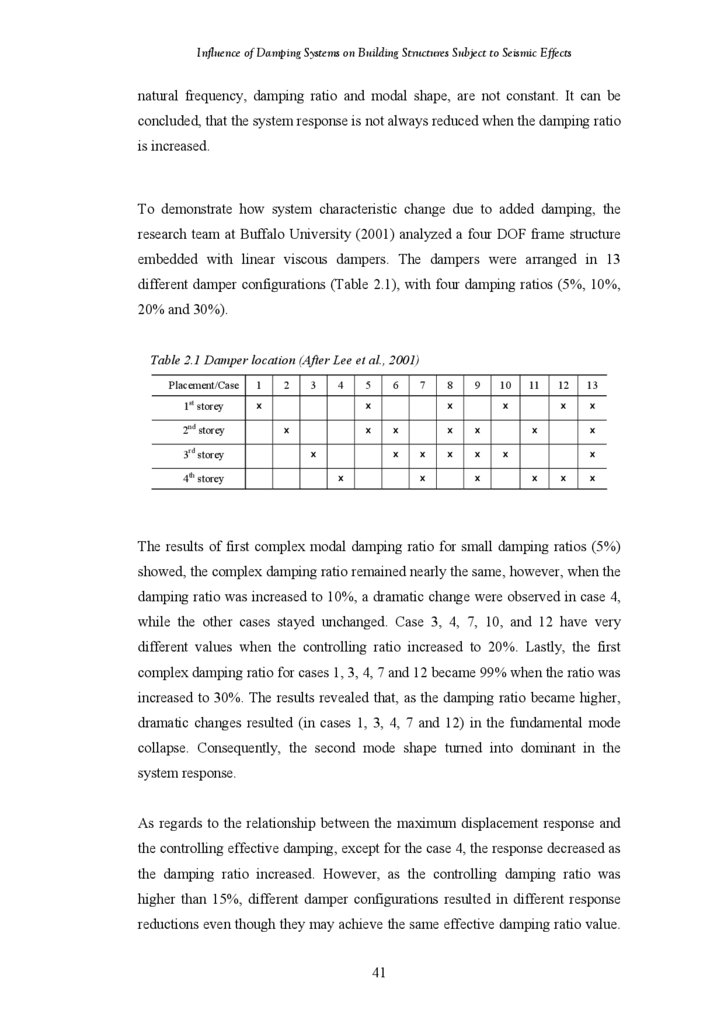
Damper Location
Seismic Response of Benchmark Models
Seismic Response of Analytical Models
Results of Frame Deflection (after Marcelin)
Results of Frame Deflection (ABAQUS)
Tip Deflection and Acceleration of the Undamped Structure
Percentage Reductions in Tip Deflection of the All Models
Percentage Reductions in Tip Acceleration of the All Models
Percentage Reductions in Tip Deflection of Structure Type T1
Percentage Reductions in Tip Acceleration of Structure Type T1
Percentage Reductions in Tip Deflection of Structure Type T3
Percentage Reductions in Tip Acceleration of Structure Type T3
Percentage Reductions in Tip Deflection of Structure Type T1-3
Percentage Reductions in Tip Acceleration of Structure Type T1-3
Tip Deflection and Tip Acceleration of the Undamped 18-Storey Structure
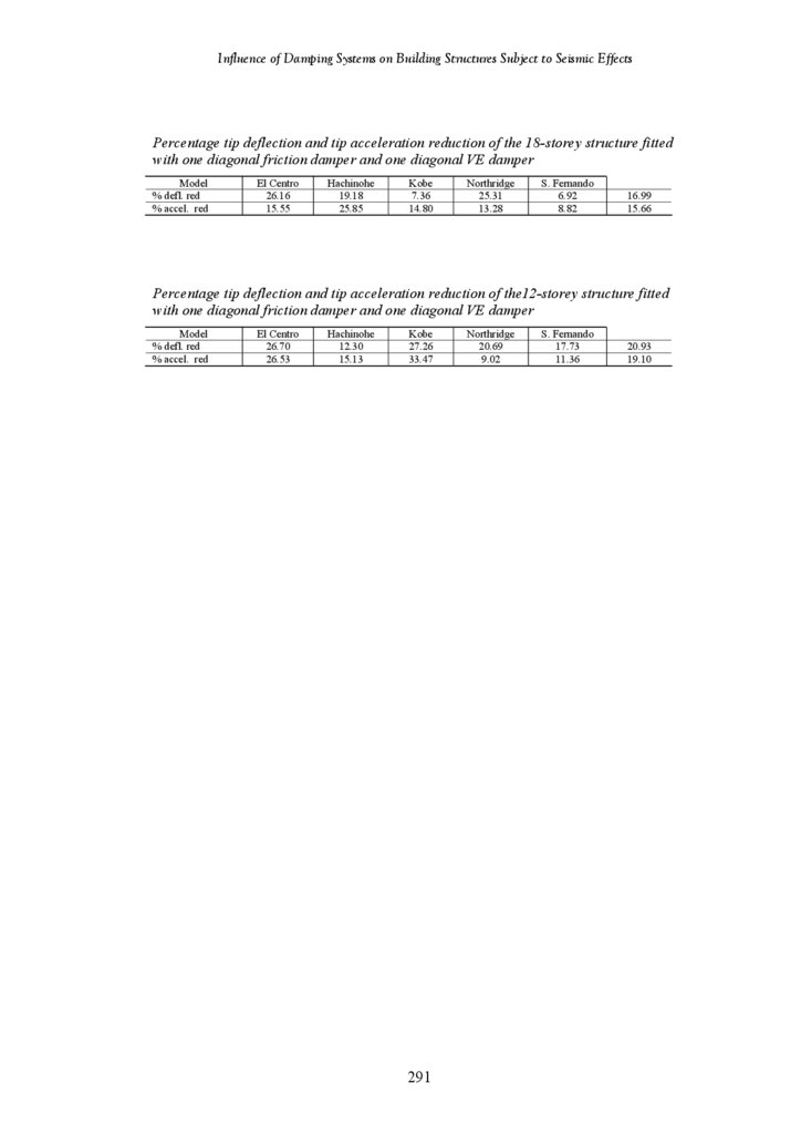
Percentage Tip Deflection and Acceleration Reduction of the Structure
Fitted with 1 Diagonal Friction Damper and 1 Diagonal VE Damper
Tip Deflection and Tip Acceleration of the Undamped 12-Storey Structure
Percentage Tip Deflection and Acceleration Reduction of the Structure
Fitted with 1 Diagonal Friction Damper and 1 Diagonal VE Damper
xvi
42
85
87
89
90
94
102
103
106
108
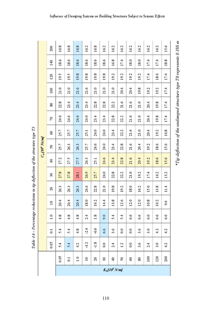
111
113
116
118
131
181
199
251
19.
Influence of Damping Systems on Building Structures Subject to Seismic EffectsSymbols
A
Ag
C
Cd
Cc
CM
C0
D
f
fc
fe
f c’
Ec
F
FD
FM
Fvd
G
G’
G”
h
h
I
J
K
kd
m
M
p
Q
t
t
T
u
ud
ug
U
Ů
Ü
Shear Area
Tributary Area of the Slab
Structural Damping Matrix
Damping Coefficient of VE Damping Device
Damping Coefficient of the Corrector
Damping Coefficient of the Main Spring
Zero Frequency Damping Coefficients
Control Force-Location Matrix
Magnification Factor
Vector of Forces in the Supplemental Device
External Excitation Vector
Compressive Strength
Young’s Modulus
Overall Force
Force along the Axis of the Damper
Force in the Main Spring
Force in the Device
Gravity Load
Viscoelastic Damper Shear Storage Modulus
Viscoelastic Damper Shear Loss Modulus
Participation Matrix which Consists of Vector of Floor Masses
Height above the Structural Base of the Structure to Level x
Importance Factor
Optimal Placement and Design of the Control System
Structural Stiffness Matrix
Axial Stiffness of Damping Device
Lumped Mass
Total Mass Matrix of the Structure
Contact Pressure
Live Load on the Structure
Temperature
Thickness of Viscoelastic Material
Natural Period
Interstorey Drift Vector
Damper Relative Displacement
Earthquake Ground Displacement
Vector of Displacement of Structure
Vector of Velocity
Vector of Acceleration
U id
Real Value of Displacement Response Associate with the Modal Shape
U iv
Real Value of Velocity Response Associate with the Modal Shape
xvii
20.
Influence of Damping Systems on Building Structures Subject to Seismic EffectsV
W
x
X
Δci
γ
μ
ρ
τ
τ max
υ
ω
ψ id
ψ iv
ζ
Velocity
Weight
Displacement of Damper
Modal Response
Damping Coefficient of the Damper Installed at the i Floor Deflection
Shear
Coefficient of Friction
Damper Angle
Density (kg/m3)
Shear Stress
Maximum Shear Stress
Poisson’s Ratio
Circular Frequency
Displacement Mode Shape
Velocity Mode Shape
Modal Damping Ratio
Abbreviations
ADAS
ASCE
EDD
EDR
EDS
FEA
FEM
FEMA
FVED
LCVA
LED
MCEER
MDOF
MTMD
PGA
OCT
SDOF
TDA
TLD
TLCD
TMD
SMA
VDS
VE
Added Damping and Stiffness
American Society of Civil Engineers
Energy Dissipation Device
Energy Dissipating Restraint
Energy Dissipation System
Finite Element Analysis
Finite Element Method
Federal Emergency Management Administration
Friction-Viscoelastic Damper
Liquid Column Vibration Absorber
Lead Extrusion Damper
Multidisciplinary Center for Earthquake Engineering Research
Multi Degree of Freedom
Multi Tuned Mass Damper
Peak Ground Acceleration
Optimal Control Theory
Single Degree of Freedom
Transient Dynamic Analysis
Tuned Liquid Damper
Tuned Liquid Column Damper
Tuned Mass Damper
Shape Memory Alloy
Viscous Damping System
Viscoelastic
xviii
21.
Influence of Damping Systems on Building Structures Subject to Seismic EffectsStatement of Original Authorship
The work contained in this thesis has not been previously submitted for a degree
or diploma at any higher education institution. To the best of my knowledge and
belief, the thesis contains no material previously published or written by another
person except where due reference is made.
Signature:
______________________________________
Date:
_______________________________________
xix
22.
Influence of Damping Systems on Building Structures Subject to Seismic EffectsAcknowledgements
I am extremely grateful and deeply indebted to my supervisor Prof. David
Thambiratnam for his enthusiastic and expertise guidance, constructive
suggestions, encouragements throughout the course of this study and the valuable
assistance in many ways. Without such assistance this study would not have been
what it is. His immense patience and availability for comments whenever
approached, even amidst his heavy pressure of work throughout the entire period
of study, deserves grateful appreciation. Adjunct Professor, Nimal Perera, is to be
mentioned with thanks for kindly agreeing to serve as associate supervisor.
I would like to thank Queensland University of Technology and the Centre for
Environment and Engineering Research for providing Postgraduate Research
Scholarship to carry out my research project. I would also like to thank the
Physical Infrastructure Centre and the Faculty of Build Environment &
Engineering for providing financial support, necessary faculties and technical
support.
It is pleasure to thank fellow post-graduate students and friends for their support
and contribution to this research. Finally, I wish to express my appreciation to my
wife Jana for her support, encouragement, and patience.
xx
23.
Influence of Damping Systems on Building Structures Subject to Seismic Effectsxxi
24.
Chapter 1Introduction
i
25.
Influence of Damping Systems on Building Structures Subject to Seismic EffectsChapter 1: Introduction
1.1 Background to the study
Earthquakes are one of nature’s greatest hazards to life on this planet and have
destroyed countless cities and villages on virtually every continent. They are one
of man’s most feared natural phenomena due to major earthquakes producing
almost instantaneous destruction of buildings and other structures. Additionally,
the damage caused by earthquakes is almost entirely associated with man made
structures. As in the cases of landslides, earthquakes also cause death by the
damage they induce in structures such as buildings, dams, bridges and other works
of man. Unfortunately many of earthquakes give very little or no warning before
occurring and this is one of the reasons why earthquake engineering is complex.
On average about 200 large magnitude earthquakes occur in each decade
(www.iris.edu). About 10-20% of these earthquakes occur mid ocean, and hence
cause no problems for human settlements. Others occur in the areas away from
towns and cities and so similarly cause few problems. The problem occurs when
an earthquake hits highly populated areas. Unfortunately as the population of the
earth increases the chances of this happening also increases. At the start of the
century, less than one in three large earthquakes killed someone, it has now risen
to two in three and this upward tend shows no signs of abating.
Some of the major problems relating to earthquake design are created by the
original design concept chosen by the architect. No engineer can truly transform a
badly conceived building into an earthquake resistant building. The damages
which have occurred during earthquake events clearly demonstrate that the shape
of a building is crucial to how they respond. The ideal aspects of a building form
are simplicity, regularity and symmetry in both elevation and plan. These
properties all contribute to a more predictable and even distribution of forces in a
structure while any irregularities are likely to lead to an increased dynamic
response, at least in certain locations of the structure. Also buildings, which are
tall in comparison to their plan area, will generate high overturning moments
while buildings with large plan areas may not act as expected due to differences in
2
26.
Influence of Damping Systems on Building Structures Subject to Seismic Effectsground behaviour, which are not always predictable. This causes different parts of
the building to be shaken differently creating obvious problems. Torsion from
ground motion could be of great concern due to eccentricity in the building layout.
For instance if the centre of mass (gravity) is not in the same position as the centre
of resistance a torsional moment about a vertical axis will be created which will
have to be designed for. In order to achieve satisfactory earthquake response of a
structure, three methods can be identified as being practical and efficient. These
are; isolation, energy absorption at plastic hinges and use of mechanical devices
to provide structural control.
The first type, the method of structural isolation is very efficient, but expensive
and difficult to carry out (Di Sarno et al., 2005). The principle behind isolation is
to change the natural period of the structure, substantially decouple a structure
from the ground motion input and therefore reduce the resulting inertia force the
structure must resist. This is done by the insertion of energy absorbing material
between the substructures and superstructures, which will reduce the amount of
seismic forces transmitted. In traditional structures, subjected to random and/or
unpredictable loads, plastic hinges are provided. These plastic hinges, which
suffer inelastic deformation are generally concentrated at the beam-column joints
and are thus associated with damage to the primary structural elements.
On the other hand, installations of mechanical energy absorbers, which are most
promising and on which this study concentrated, do as their name suggests. They
absorb the energy from the earthquake reducing the effects on the critical
components of the structure (FEMA 274). After the earthquake these absorbers,
which do not themselves support the structure, are replaced leaving the building
undamaged. Once again cost is a factor as neither of the concepts can be justified
by cost alone.
There are two types of structural control provided by the addition of mechanical
devices, active and passive control. Active control requires a power supply to
activate the dampers and hence may be undependable during seismic events where
the power supply could be disrupted. For this reason, dampers with active control
3
27.
Influence of Damping Systems on Building Structures Subject to Seismic Effectshave been tested on tall buildings subjected to wind induced loading rather the
more unpredictable cyclic loading caused by earthquakes. On the other hand,
passive energy dissipation systems have emerged as special devices that are
incorporated within the structure to absorb a portion of the input seismic energy.
As a result, the energy dissipation demand on primary structural members is often
considerably reduced, along with the potential for structural damage (FEMA 274).
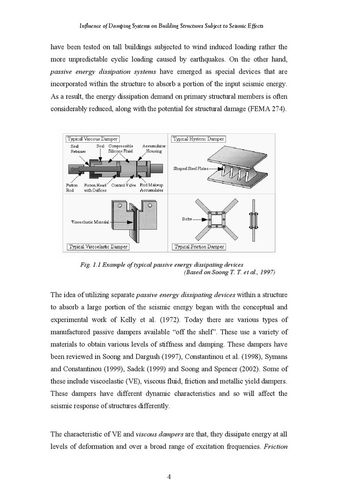
Fig. 1.1 Example of typical passive energy dissipating devices
(Based on Soong T. T. et al., 1997)
The idea of utilizing separate passive energy dissipating devices within a structure
to absorb a large portion of the seismic energy began with the conceptual and
experimental work of Kelly et al. (1972). Today there are various types of
manufactured passive dampers available “off the shelf”. These use a variety of
materials to obtain various levels of stiffness and damping. These dampers have
been reviewed in Soong and Dargush (1997), Constantinou et al. (1998), Symans
and Constantinou (1999), Sadek (1999) and Soong and Spencer (2002). Some of
these include viscoelastic (VE), viscous fluid, friction and metallic yield dampers.
These dampers have different dynamic characteristics and so will affect the
seismic response of structures differently.
The characteristic of VE and viscous dampers are that, they dissipate energy at all
levels of deformation and over a broad range of excitation frequencies. Friction
4
28.
Influence of Damping Systems on Building Structures Subject to Seismic Effectsdampers, on the other hand, dissipate energy only when the slip force is reached
and exceeded. Metallic yield dampers dissipate energy through the inelastic
deformation of the material. A combination of these dampers can be used within
the structural system to effectively damp out the high and low frequency content
of earthquakes. This is commonly referred to as a hybrid system.
1.2 Research Problem
As mentioned in the previous section, the use of passive energy dissipation
devices has become very popular in the recent years. However, the vast majority
of applications was realised within frame structures, while investigations on use of
damping devices within cut outs of shear wall is still very limited. For this reason
the aim of this research is to investigate the behaviour of multi-storey frame-shear
wall building structures under earthquake loads with damping devices
strategically located within the cut outs of the shear wall The research will
evaluate the influence of different damping systems on
the overall seismic
response of the structure.
Friction, VE, and hybrid friction-VE damping mechanisms of different size,
configuration and placed at various locations were treated. The damping
mechanisms were modelled as a contact pair with friction parameter for a friction
damper, a linear spring and dash-pot in parallel for the VE damper, and a hybrid
damper consisting of both a friction and a VE damping mechanism.
Finite element techniques with time history analysis were employed to investigate
the effect of these damping systems under seismic loading of five different
earthquake excitations. For the purposes of this study, the program selected for the
numerical analysis was ABAQUS / Standard version 6.3. This is a general
purpose finite element program that has been designed to solve a wide range of
linear and non-linear problems involving static, dynamic, thermal and electrical
response of systems. In conjunction with this program MSC / PATRAN Version
2004 was used as the pre-processor for generating the geometry, element mesh,
boundary conditions and loading conditions, and as the post-processor for viewing
5
29.
Influence of Damping Systems on Building Structures Subject to Seismic Effectsthe results of the analysis, and generating graphs of the response of buildings. A
direct integration dynamic analysis was selected to obtain the response of the
structures under earthquake loading. This analysis assembles the mass, damping
and stiffness matrices and solves the equation of dynamic equilibrium at each
point in time. The response of the structure was obtained for selected time steps of
the input earthquake accelerogram.
To study the effectiveness of the damping systems in mitigating the seismic
response, the tip displacements and accelerations of each structure were acquired
from the results of the analysis and compared with those of undamped structure.
1.3 Aims and objectives
The main aim of this project is to generate fundamental research information on
the seismic performance of building structural systems having passive damping
devices installed within shear walls.
Additional objectives are:
¾ Create computer models of building structures – damper systems for
investigation
¾ Study the effects of important parameters such as damper properties, locations
and configuration of the dampers and earthquake types
¾ Use the research findings to propose more effective damping system for
seismic mitigation.
1.4 Method of investigation
¾ This research was carried out using computer simulations. Finite element
models of the shear wall of buildings was set up and analysed under five
earthquake excitations
¾ The damping mechanisms were modelled as a linear spring and dash-pot in
parallel for the VE damper, a contact pair with friction parameter for a friction
damper and a hybrid damper consisting of both a VE and a friction damping
mechanism
6
30.
Influence of Damping Systems on Building Structures Subject to Seismic Effects¾ Size and material properties of the structure, damping properties,
configuration and location of dampers, and earthquake types, were parameters
in this investigation and the influence of these was studied
¾ Evaluation of results and reporting major findings.
1.5 Scope of research
This research investigates seismic response of building structures with embedded
dampers. The main response parameters are tip deflection and tip acceleration of
the structure. The scope of this investigation is as follow:
-Building structures
¾ Frame shear wall structure is the range of height 48 m to 96 m
¾ The structures have natural frequencies within the range of dominant
frequencies of the earthquakes treated here
-Damping mechanisms
¾ Friction, viscoelastic and combined friction-viscoelastic dampers are
considered
-Damper configurations
¾ Diagonal, chevron braced, combined diagonal-chevron braced and lower
toggle configurations are used
-Damper locations
¾ Across the height of the structures with the dampers installed in one, two
or three at a time
-Seismic records
¾ Five different earthquakes, each with different duration of strong motion
and range of dominant frequencies were used. All the seismic records
were scaled to have the same peak ground accelerations to facilitate
comparison and to suite Australian (low) seismic conditions.
The comprehensive investigation treating all the above parameters will provide
results, which can be used to establish:
¾ The feasibility of using embedded dampers in seismic mitigation and
¾ Placement of dampers for the best results for different structures.
7
31.
Influence of Damping Systems on Building Structures Subject to Seismic Effects1.6 Layout of thesis
The material contained in this thesis is presented as seven chapters. They are the
following:
Chapter 1
Introduction
Presents the background and introduction to the topic, defines
research problem, states the aims and objectives and outlines
the method of investigation used in this research project.
Chapter 2
Literature Review
Highlights a review of previous literature published on the
behaviour of a passive energy dissipation devices used in
building structures under seismic loading. It then identifies the
need and scope of the present research.
Chapter 3
Model Development and Verification of Results
This chapter describes the method of investigation and the
building structures and damping systems used in this research
project. The development of finite element models and some
model calibration are also presented.
Chapter 4
Results – High-Rise Structures
The results of finite element analyses of high-rise frame-shear
wall structures, 24 storey high, embedded with five types of
damping systems obtained under variety of earthquake
excitations are presented.
Chapter 5
Results – 18-Storey Structures
The results of finite element analyses of 18-storey frame-shear
wall structures embedded with six types of damping systems
obtained under variety of earthquake excitations. Evaluation of
results and application of findings to establish damping
systems for best results.
Chapter 6
Results – 12-Storey Structures
The results of finite element analyses of 12-storey frame-shear
wall structures embedded with six types of damping systems
obtained under different earthquake excitations. Evaluation of
results and application of findings to establish best damping
model.
Chapter 7
Conclusions and Recommendations
Highlights the major results and the main contributions of this
research and makes some recommendations for further
research.
8
32.
Influence of Damping Systems on Building Structures Subject to Seismic EffectsChapter 2
Literature Review
9
33.
Influence of Damping Systems on Building Structures Subject to Seismic EffectsChapter 2: Literature Review
2.1 Introduction
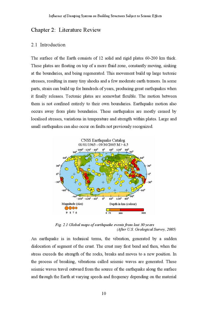
The surface of the Earth consists of 12 solid and rigid plates 60-200 km thick.
These plates are floating on top of a more fluid zone, constantly moving, sinking
at the boundaries, and being regenerated. This movement build up large tectonic
stresses, resulting in many tiny shocks and a few moderate earth tremors. In some
parts, strain can build up for hundreds of years, producing great earthquakes when
it finally releases. Tectonic plates are somewhat flexible. The motion between
them is not confined entirely to their own boundaries. Earthquake motion also
occurs away from plate boundaries. These earthquakes are mostly caused by
localised stresses, variations in temperature and strength within plates. Large and
small earthquakes can also occur on faults not previously recognized.
Fig. 2.1 Global maps of earthquake events from last 30 years
(After U.S. Geological Survey, 2005)
An earthquake is in technical terms, the vibration, generated by a sudden
dislocation of segment of the crust. The crust may first bend and then, when the
stress exceeds the strength of the rocks, breaks and moves to a new position. In
the process of breaking, vibrations called seismic waves are generated. These
seismic waves travel outward from the source of the earthquake along the surface
and through the Earth at varying speeds and frequency depending on the material
10
34.
Influence of Damping Systems on Building Structures Subject to Seismic Effectsthrough, which they move. The two general types of vibrations produced by
earthquakes are surface waves, which travel along the Earth's surface, and body
waves, which travel through the Earth. Surface waves usually have the strongest
vibrations and probably cause most of the damage done by earthquakes.
Body waves are of two types, compressional and shear. Both types pass from the
focus of an earthquake to distant points on the surface, but only compressional
waves travel through the Earth's molten core. Compressional waves, called “P
wave” travel at great speeds and push tiny particles of Earth material directly
ahead of them or displace the particles directly behind their line of travel. Shear
waves, called “S waves” do not travel as rapidly through the Earth's crust and
mantle as do compressional waves, and they ordinarily reach the surface later.
Instead of affecting material directly behind or ahead of their line of travel, shear
waves displace material at right angles to their path and therefore sometimes
called "transverse" waves.
If the earthquake occurs in a populated area, it may cause many deaths, injuries
and extensive property damage. However, the earthquakes of large magnitude do
not necessarily cause the most intense surface effects. The earthquake's
destructiveness in a given region depends on local surface and subsurface
geologic conditions. An area underlain by unstable ground is likely to experience
much more noticeable effects than an area equally distant from an earthquake's
epicentre but underlain by firm ground such as granite. In addition to magnitude
and the local geologic conditions level of destruction depends on other factors.
These factors include the focal depth, the distance from the epicentre, the density
of population, constructions in the area shaken by the quake and the design of
building structures.
2.2 Seismic design concept
In conventional seismic design, acceptable performance of a structure during
earthquake excitation is based on the lateral force resisting system being able to
absorb and dissipate energy in a stable manner for a large number of cycles
11
35.
Influence of Damping Systems on Building Structures Subject to Seismic Effects(Constantinou et al., 1998). Conventional design approach is not applicable in
situations when a structure must remain functional after earthquake. In such cases,
the structure must be designed with sufficient strength to minimize the inelastic
deformations, however, this approach is very expensive. Furthermore, in such
structures, special precautions need to be taken in safeguarding against damage of
important secondary system, which are needed for continuing serviceability. Over
the past couple of decades the astounding developments in alternate design
strategies have been made, which incorporate, earthquake protective systems in
the structure. These protective systems are in the form of:
1) Seismic isolation systems:
¾ Elastomeric bearings
¾ Lead rubber bearings
¾ Combined elastomeric and sliding bearings
¾ Sliding friction pendulum system
¾ Sliding bearings with restoring force
2) Supplemental energy dissipation devices:
Passive energy dissipation
Semi-active and Active systems
¾ Metallic dampers
¾
Active bracing systems
¾ Friction dampers
¾
Active mass dampers
¾ VE solid dampers
¾
Variable stiffness and damping systems
¾ VE or viscous fluid dampers
¾
Smart materials
¾ Tuned mass dampers
¾ Tuned liquid dampers
Conventional design approach, seeks to prevent occurrence of inelastic
deformations by allowing structural members to absorb and dissipate the
transmitted earthquake energy by inelastic cyclic deformations in specially created
regions. This strategy implies that some damage may occur, possibly to the extent
that the structure is no longer repairable.
The method of structural isolation deflects or filters out the earthquake energy by
interposing a layer with low horizontal stiffness between the structure and the
12
36.
Influence of Damping Systems on Building Structures Subject to Seismic Effectsfoundation. The structural isolation system includes wind resistant and tie down
system and also includes supplemental energy dissipation devices to transmit
force between the structure above the isolation system and the structure below the
isolation system. The structural isolations are suitable for a large class of
structures that are short to medium height, and whose dominant modes are within
a certain frequency range. However, in an earthquake rich in long period
components, it is not possible to provide sufficient flexibility for the reflection of
the earthquake energy. Several building and bridges have now been installed with
base isolation systems (for example Tokyo Port Terminal, Tohoku Electric Power
Company, University of Southern California Teaching Hospital, Los Angeles,
Marina Apartments San Francisco).
Fig. 2.2 Base isolation
(Based on Shustov V., 1994)
Another approach to improving earthquake response performance is that of
supplemental energy dissipation systems. The primary reason for introducing
energy dissipation systems into building frames is to reduce the displacement and
damage in the structure. Displacement reduction is achieved by adding either
stiffness and/or energy dissipation to the building structure. In these systems,
mechanical devices are incorporated into the frame of the structure and absorb the
energy from the earthquake reducing the drift as well effects on the critical
components of the structure. These mechanical energy dissipating devices have
been found to be quite promising and their applications form the focus of this
study.
13
37.
Influence of Damping Systems on Building Structures Subject to Seismic Effects2.3 Analysis procedures
Today, there are a number of methods available for building structures subjected
to seismic loading (Newmark and Hall, 1987, Krinitzsky et al., 1993, Fagan,
1992). Four of them, namely linear static, linear dynamic, non-linear static, nonlinear dynamic, are described in great details in FEMA 273/274.
2.3.1 Static analysis procedures
A static analysis is a quick and easy way to obtain an approximate response of a
structure. Generaly, this method determines the distribution of the earthquake base
shear force, in given direction, throughout the height of a structure. According
linear static procedures, static lateral forces are applied to the structure to obtain
design displacements and forces (FEMA 273/274). The method is based on two
important assumptions. First, it is implied that an adequate measure of
designactions can be obtained using a static analysis, eved though seismic
response is dynamic. Second, it is implied that an adequate measure of design
actions can be obtained using a linearly-elastic model, even though nonlinear
response to strong ground shaking may be anticitated. The guidelines provides
also criteria to determine when nonlinear procedures are required as an
alternative. Preferebly, the evaluation of a nonlinear deformations should be
carried out using nonlinear procedures that explicitly account for nonlinear
deformations in deformed components. As an option, the guidelines permit
evaluation to be carried out using linear procedures. In a linear procedure, there is
direct relation between internal forces and internal deformation for all types of
loading. Hence, when using linear procedures, it is simpler to express
acceptability in terms of internal forces rather than internal deformations (FEMA
273/274).
2.3.2 Dynamic analysis procedures
Similarly as the linear static, also the linear dynamic procedure uses the same
linearly-elastic structural model. The linear dynamic procedure provide greater
insight into the structural response, however, similarly to linear static procedure, it
does not explicitly account for effect of nonlinear response. On the othe hand, in
14
38.
Influence of Damping Systems on Building Structures Subject to Seismic Effectsthe case of nonlinear dynamic procedure, the nonlinear load-deformation
behaviour of individual components and elements is modeled directly in the
mathematical model. There are two general types of dynamic analysis to choose
from for structures subjected to seismic ground motions, which are the response
spectrum and type history analysis.
The response spectrum is defined as a graphical relationship of the maximum
acceleration response of a SDOF elastic system for various values of natural
period, T, obtained by changing the structural properties, with damping to the
dynamic motion of force (Newmark and Hall, 1987). The response spectrum
requires dynamic analysis of a structure to establish modal frequencies and mode
shapes. Using standard mathematical procedures (Clough and Penzien, 1993) and
a response spectrum corresponding to the damping in the structure, the modal
frequencies and shapes are used to establish spectral demands. The spectral
demands are then used to calculate displacements, forces, storey shears and base
reactions for each mode of response considered. Consequently, all these results
are combined by using established rule to calculate total response quantities
(FEMA 273/274).
The time history analysis determines the response of a structure due to forces,
displacements, velocities or accelerations that vary with time. There are two types
of this method, fist is direct integration and the second, modal superposition
(Clough and Penzien, 1975). Modal superposition is only suitable for linear
analysis, whereas direct integration can be used also for nonlinear analysis. The
direct integration utilize a step-by-step solution of equation of motion, which is
generaly described as:
MU&& + CU& + KU = F (t )
(2.1)
where, M,C,K are the mass, the damping, and the stiffness matrices, respectively,
U, U& , and U&& are the displacement, velocity and acceleration vectors,
respectively, F(t) is the vector of applied forces, which may varied with time. The
most popular integration scheme is the Newmark-β method, which is implicit and
unconditionally stable. The following approximations are made in this method:
15
39.
Influence of Damping Systems on Building Structures Subject to Seismic Effects{U& }
t + dt
dt
= {U& }t + ({U&&}t + {U&&}t + dt )
2
(2.2)
{U }t + dt = {U }t + {U& }dt + ⎛⎜⎜ ⎛⎜ 1 − β ⎞⎟{U&&}t + β {U&&}t + dt ⎞⎟⎟(dt )2
⎝⎝ 2
⎠
⎠
(2.3)
where, dt is the time step of the analysis, and β is the structural damping depend
on an amplitude decay factor, but usually a value of 0.25 is used.
2.4 Passive energy dissipation devices
The function of Seismic Isolation and Energy Dissipation System is to reduce
structural response due to earthquake, wind and other dynamic loads. These
devices, which are also known as motion control system, can absorb part of the
energy induced in the structure, reducing energy dissipation demand on the
primary structural members, and thus reducing the structural deflection and nonstructural deformations. The term control systems denotes what was previously
termed energy dissipation system, whereas the terms passive and semiactive
denote, respectively, systems that require no externally supplied power and
systems that require minimal externally supplied power to operate.
Passive control system develops control forces at the points of attachment of the
system. The power needed to generate these forces is provided by the motion of
the points of attachment during dynamic excitation. The relative motions of these
points of attachment determine the amplitude and direction of the control forces.
On the other hand, an active control system develops motion control forces.
However, the magnitude and direction of these forces are determined by a
controller based on information from sensors and control strategy and supplied by
the active control system. An active control system should, in principle provide
for more versatile response control, however, they require a power supply to be
activated and hence may be undependable during seismic events where the power
supply could be disrupted. For this reason, dampers with active control have been
tested on tall buildings subjected to wind induced loading rather than the more
unpredictable cyclic loading caused by earthquakes.
16
40.
Influence of Damping Systems on Building Structures Subject to Seismic EffectsA semi-active Control System generally originated from passive control systems,
which was modified to allow for adjustment of their mechanical properties
(shearing of viscous fluid, orificing of fluid or sliding friction). The mechanical
properties of semi-active control systems may be adjusted by a controller. Power
source required for the semi-active control system is typically very small and
remotely related to the power output of the system.
Fig. 2.3 Example of semi-active control system
(Based on Kobori et al., 1995)
In the last two decades, variety of energy dissipation devices (EDD) has been
developed to enhance safety and reduce damage during earthquake excitations.
These devices utilize a wide range of material and technologies as a means to
increase the damping, stiffness and strength characteristics of structures. Energy
dissipation may be achieved either by the transformation of kinetic energy to heat
or by the transferring of energy among vibrating modes.
17
41.
Influence of Damping Systems on Building Structures Subject to Seismic EffectsThe first mechanism includes either hysteretic devices, which dissipate energy
without considerable rate dependence, and VE or viscous devices, which, in
contrast, exhibit substantial rate dependence. Hysteretic devices operate on
principles such as yielding of metals and frictional sliding, while VE or viscous
devices involving deformation of VE solids or viscous fluids and those employing
fluid orificing. The second mechanism consists of re-centering devices that utilize
either a preload generated by fluid pressurization or internal springs, or a phase
transformation to produce modified force-displacement response that includes a
natural re-centering component.
2.4.1 Hysteretic energy dissipation devices
A variety of hysteretic energy dissipation devices has been proposed and
developed to enhance structural protection. Most of these devices generate
rectangular hysteresis loop (Fig. 2.4), which indicates that behaviour of friction
dampers is close to that of Coulomb friction. The simplest models of hysteretic
behaviour involve algebraic relation between force and displacement. Hence,
hysteretic systems are often called displacement dependant.
Fig. 2.4 Idealized force-displacement loops of hysteretic devices
(Based on Soong et al., 1997)
In general, hysteresis devices dissipate energy through a mechanism that is
independent of the rate of load frequency, number of load cycles, or variation in
temperature. In addition, hysteresis devices have high resistance to fatigue.
Hysteresis devices include metallic dampers that utilize the yielding of metals as
the dissipative mechanism, and friction dampers that generate heat through dry
18
42.
Influence of Damping Systems on Building Structures Subject to Seismic Effectssliding friction. The both types of devices are inherently non-linear, that means,
that the force output does not scale with the displacement, and significant path
dependence is apparent. The non-linearity of hysteretic devices must be
considered in structural analysis as well as in design. It should also be noted that
energy dissipation occurs only after a certain threshold force is exceeded.
2.4.1.1 Metallic dampers
Metallic dampers utilize the hysteretic behaviour of metals in the inelastic range.
The resisting forces of the dampers, consequently, depend on the nonlinear stressstrain characteristics of the metallic material. A wide variety of damping devices
that utilize shear, flexure and material deformation in the plastic range have been
developed and tested. The most desirable characteristic of these devices are their
stable hysteretic behaviour, low-cycle fatigue property, long term reliability, and
relative insensitivity to change in temperature. In addition, these devices are
relatively inexpensive and their properties will remain stable over the long lives of
structures. Disadvantages of these devices are their limited number of working
cycles and their non-liner response.
Fig. 2.5 Two examples of X-shaped plate dampers
(Based on Whittaker et al., 1991)
X-shaped plate dampers are probably the most popular among the metallic
dampers. The parallel metallic plate used to be installed within a frame bay
between a chevron brace and the overlying beam. Consequently, the dampers
19
43.
Influence of Damping Systems on Building Structures Subject to Seismic Effectsprimarily resist the horizontal forces related to inter-storey drift via flexural
deformation of the individual plates. Beyond a certain level of force, the plates
yield and hence provide substantial energy dissipation. The tapered shape of the
plates generates nearly uniform yielding over the entire plate surface.
X-shaped plate dampers consisting of multiple X-shaped steel plates were
introduced by Bechtel Power Corporation. Comprehensive experimental studies
of these dampers have been carried out by Bergman et al., (1987) and Whittaker et
al., (1991). Some applications of non-linear structural analysis to building frames
incorporating metallic dampers can also be found in Xia and Hanson (1992), Jara
et al., (1993). There are also several interesting alternatives to the modified
Newton-Raphson algorithm. Variations of the steel cross-bracing dissipaters have
been developed in New Zealand, Italy and USA. The results of these studies
showed that the X-shaped plate dampers exhibited good performance and proved
to be stable under large axial loads in the device.
Fig. 2.6 Triangular shaped damper and its hysteresis loops
(Based on Tsai et al., 1997)
Triangular plate dampers were originally developed in New Zealand and used in
several base isolation applications. Later, after experimental work carried out by
Tsai and Hong (1992), they were also used in buildings. Triangular steel yielding
devices have also been used in Japan. Device similar to the triangular plate
20
44.
Influence of Damping Systems on Building Structures Subject to Seismic Effectsdampers was developed by Obayashi Corporation (Soong and Constantinou,
1994). Another device, a yielding damper consisting of a short lead tubes loaded
to deform in shear was developed for developed by Sakurai et al., 1992).
Yielding steel bracing systems fabricated from round steel bars for cross-braced
structure have been developed in New Zealand (Skinner et al., 1980; Tyler, 1985).
Energy is dissipated by inelastic deformation of the rectangular steel frame in the
diagonal direction of the tension brace, as shown in Fig. 2.7. Several
modifications of the steel cross–bracing dissipater have been developed and
installed in Italy (Ciampi, 1991).
Fig. 2.7 Yielding steel bracing system
(Based on Tyler et al., 1985)
All these metallic yielding dampers may be effective in reducing the response of
structures to earthquake loading. The post-yielding deformation range of these
dampers is a major concern, which should be addressed to insure that the dampers
can sustain a sufficient number of cycles of deformation without premature
fatigue. Another problem, which should be worked out carefully, is the stable
hysteretic behaviour of the dampers under repeated inelastic deformation.
Lead extrusion damper (LED) represents another class of dampers, which utilized
the hysteretic energy dissipation properties of metal. The process of extrusion
consists of forcing a lead piston through a hole or an orifice, thereby changing its
shape. LEDs were first suggested by Robinson et al., (1987), as a passive energy
21
45.
Influence of Damping Systems on Building Structures Subject to Seismic Effectsdissipation device for base isolated structures in New Zealand. As it can be seen
from Fig. 2.8, there are two types of LEDs introduced by Robinson. The first
device consists of a thick-walled tube and a co-axial shaft with a piston. There is a
constriction on the tube between the piston heads and the space between the
piston heads is filled with lead. The central shaft extends beyond one end of the
tube. When external excitation occurred, the piston moves along the tube and the
lead is forced to extrude back and forth through the orifice formed by the
constriction of the tube.
Fig. 2.8 Two examples of lead extrusion devices
(Based on Robinson et al., 1987)
The second type of LED is similar to the first one, except that the extrusion orifice
is formed by a bulge on the central shaft rather than by a constriction in the tube.
The shaft is supported by bearings which also serve to hold the lead in place. As
the shaft moves, the lead must extrude through the orifice formed by the bulge and
tube. Similar to most friction devices, the hysteretic behaviour of LED is
essentially rectangular.
The load deformation relationship of LED is stable and unaffected by the number
of loading cycles. They have a long life and do not have to be replaced or repaired
after an earthquake excitation since the lead in the damper returns to its
22
46.
Influence of Damping Systems on Building Structures Subject to Seismic Effectsundeformed state after excitation. The lead extrusion devices are insensitive to
environmental conditions and aging effects.
2.4.1.2 Friction dampers
A wide variety of friction dampers has been developed and installed in building
structures. Friction dampers can provide mechanism for dissipation of large
amount of energy and they have good performance characteristics and their
behaviour is less affected by the load frequency, number of load cycles, or
changes in temperature. Friction damper exhibit rigid-plastic behaviour and force
response is modelled by Coulomb friction.
X-braced damper was proposed by Pall et al., (1982). In this type of damper, the
braces in a moment resisting frame incorporated frictional devices. When load is
applied to this damper, the tension brace induces slippage at the friction joint.
Consequently, the four links force compression brace to slip. Energy is dissipated
in both braces even though they were designed to be effective in tension only.
However, this is only valid if the slippage of the device is sufficient to completely
straighten any buckled braces.
Fig.2.9 Pall friction damper
(Based on Pall and Marsh, 1982)
Bracing-damper system, which is a more detailed model for the device in which
each member of the bracing-damper system is represented by element reflecting
23
47.
Influence of Damping Systems on Building Structures Subject to Seismic Effectsits individual axial and bending characteristics. The structural braces are assumed
to yield in tension, but buckle elastically in compression was proposed by
Filiatrault and Cherry (1987). Bending stiffness is included to maintain stability of
the damper mechanism. The authors conducted some physical experiments from
which, made obvious, that seemingly minor fabrication details can significantly
affect the overall performance at the friction damper.
Improved Pall friction damper was developed by Wu et al., (2005). The
construction details, operation and damper force of the improved damper were
compared with those of the original Pall friction damper. The analyses and
validation experiment carried out by authors showed that the resisting forces
generated by these two dampers were identical with identical frictional forces.
Hence the improved damper replicated the mechanical properties of the original
damper, but offers some advantages in terms of ease of manufacture and
assembly.
Uniaxial friction damper (Fig. 2.10) manufactured by Sumitomo Metal Industries
Ltd., utilizes a slightly more sophisticated design. The pre-compressed internal
spring exerts a force that is converted through the action of inner and outer
wedges into a normal force on the friction pads. These copper alloy friction pads
contain graphite plug inserts, which provides dry lubrication. This helps to
maintain a consistent coefficient of friction between the pads and the inner surface
of the stainless steel casing.
Fig. 2.10 Uniaxial friction damper
(Based on Sumitomo Metal Industries Ltd 1992)
24
48.
Influence of Damping Systems on Building Structures Subject to Seismic EffectsAiken and Kelly (1990) indicated that the response of these dampers is extremely
regular and repeatable with rectangular hysteresis loops. Furthermore, the effect
of loading frequency and amplitude, number of cycles, or ambient temperature on
damper response was reported as insignificant. The reduction in displacements,
however, depend on the input ground motion because friction dampers are not
activated and do not dissipate energy for forces smaller than threshold. The
placement of the dampers did not influence base shears significantly.
Sumitomo friction damper was investigated by Aiken and Kelly (1990). The
authors performed experimental and numerical examinations of this damper
installed on 1/4-scale 9 storey steel frame in conjunction with chevron brace
assembly. The performance of the friction dampers was outstanding. The
hysteresis loops showed very consistent, nearly ideal Coulomb behaviour
throughout the duration of the test and approximately 60% of the input energy
was dissipated in the dampers.
Fig. 2.11 Installation of uniaxial friction damper in steel frame
(Based on Sumitomo Metal Industries Ltd., 1992)
Energy Dissipating Restraint (EDR) shown in Fig. 2.12 was manufactured by
Fluor Daniel, Inc. The design of this friction damper is superficially similar to the
Sumitomo damper, since this device also includes an internal spring and wedges
encased in a steel cylinder. However, there are some novel features of the EDR
that produce very different response characteristics. The EDR utilizes steel and
bronze friction wedges to convert the axial spring force into normal pressure
25
49.
Influence of Damping Systems on Building Structures Subject to Seismic Effectsacting outward on the cylinder wall. Therefore, the frictional surface is created by
the interface between the bronze wedges and the steel cylinder. Internal stops are
installed within the cylinder in order to create the tension and compression gaps.
The length of the internal spring can be changed during operation to provide a
variable friction slip force.
Fig. 2.12 Energy dissipating restraint
(Based on Fluor Daniel, Inc., 1993)
Slotted bolted damper, proposed by Fitzgerald et al., (1989) can be seen in Fig.
2.13. This damper allows slip to occur in slotted bolted connections. The
connection consists of gusset plate, two back to back channels, cover plates, and
bolts with washers. The sliding interface consists of steel.
Fig. 2.13 Three examples of slotted bolted connections
(Based on Fitzgerald et al., 1989, Grigorian et al., 1993, and Constantinou 1991)
26
50.
Influence of Damping Systems on Building Structures Subject to Seismic EffectsGrigorian and Popov (1993), introduced and tested a slotted bolted damper with
the sliding interface consisted of brass and steel. A frictional characteristic of
modified interface were a significantly more stable than those of steel interface.
Earthquake simulator tests of a three-storey steel building model with the slotted
connection have been carried out by Grigorian and Popov who showed the
effectiveness of the device in reducing the seismic response. Utilizing of graphite
impregnated bronze plates proposed by Constantinou et al., (1991), is another
alternative to improve the frictional characteristic of the slotted bolted damper.
Rotating slotted bolted friction damper with inclined slotted holes has been
successfully proposed and tested by Butterworth (1999).
Concentrically braced frame proposed by Yang and Popov (1995) is
representative of another type of friction dampers. Concentrically braced frames
offer one of the most efficient lateral loads resisting system available, which
combine strength, stiffness, low weight and simple construction. Unfortunately,
under seismic loading the applying of light tension-only tends to leads to ‘soft
storey’ failure due to irrecoverable tensile yielding. To remedy this disadvantage,
the authors suggested the used of specially detailed sliding plates moving in the
vertical plane.
2.4.2 Viscoelastic dampers
VE dampers have force displacement characteristics that are function of either the
relative velocity between the ends of the damper or the frequency of the motion.
However, the response of these devices may also be a function of relative
displacement. VE devices exhibit stiffness and damping coefficients, which are
frequency dependant. Moreover, the damping force in these devices is
proportional to velocity, that the behaviour is viscous. Research and development
of the VE dampers for seismic applications began in the early 1990s. Over the last
few years extensive experimental program has been designed and carried out for
steel frames and lightly reinforced concrete frames. VE dampers are mostly used
in structures where the damper undergoes shear deformations.
27
51.
Influence of Damping Systems on Building Structures Subject to Seismic EffectsFig. 2.14 Idealized force-displacement loop of VE devices
(Based on Soong et al., 1997)
Solid VE dampers are constructed from constrained layers of acrylic polymers or
copolymers and designed to produce damping forces through shear deformations
in the VE material. When deformed, the VE materials exhibit the combined
features of an elastic solid and viscous liquid i.e. they return to their original shape
after each cycle of deformation and dissipate a certain amount of energy as heat.
Fig. 2.15 Typical VE solid damper
(Based on Chang et al., 1995)
Several shake table tests of large-scale steel frames and reinforced concrete
frames with added VE dampers have been carried out by Ashour et al., (1987),
Fujita et al., (1991), Aiken et al., (1994), Chang et al., (1995), Foutch et al.,
(1993) and Min et al., (2004). In each of these experimental studies, VE dampers
28
52.
Influence of Damping Systems on Building Structures Subject to Seismic Effectswere found to significantly improve the response of the frame and reduce interstorey drifts and storey shears. These results have led to the development of
design procedures for structures fitted with supplemental VE dampers.
Bitumen rubber compound VE damper developed by Showa and Shimizu
corporations induces large damping forces to shear deformation and can sustain
shear strains of about 300%. The test results indicated a 50% reduction in the
seismic response of the frame. Super-plastic silicone rubber VE shear damper
developed and tested by Kumagai-Gumi Corporation at the top connection of a
wall panel to the surrounding frame. Tests of ½ scale 3-storey steel frame show
response reductions of up to 60%.
Fluid VE devices, such as viscous shear walls, operate by shearing VE fluids.
They possess the response characteristics similar to solid VE dampers, except that
the fluid VE dampers do not exhibit stiffness when loads with low frequencies are
applied (Fu and Kasai, 1999). The dampers, which utilise the viscous properties of
fluids have been developed and used in several structural applications. Forcedisplacement loop of viscous damping devices is shown in Fig.2.16.
Fig. 2.16 Idealized force-displacement loop of viscous devices
(Based on Soong et al., 1997)
Viscous-damping wall system was developed by Sumitomo Construction
Company in Japan. The device consists of an outer steel casing attached to the
lower floor, filled with a highly viscous fluid. An inner moving steel plate
hanging from the upper floor is contained within the steel casing. The viscous
damping force is induced by the relative velocity between the two floors. Arima et
29
53.
Influence of Damping Systems on Building Structures Subject to Seismic Effectsal., (1988) conducted experimental test on a full scale 4-storey steel frame with
and without viscous damping walls. The results of frame fitted with viscous walls
revealed response reductions of 66 to 80%. A 4-storey reinforced concrete
building with viscous damping walls was constructed in Tsukuba, Japan and has
since been monitored for earthquake response. The viscous damping walls
installed in the 78 m high steel frame building in Shizuoka City, Japan, provided
20 to 35% damping and reduced the building response up to 70 to 80% (Miyazaki
and Mitsusaka, 1992).
Fig. 2.17 Viscous damping wall system
(Based on Sumitomo Construction Company, 1996)
Fluid viscous dampers operate on the principle of fluid flow through orifices.
Viscous dampers can dissipate large amount of energy over a wide range of load
frequencies. The main advantage of viscous dampers is that, they can reduce
building deflection and stress at the same time. This is because the force from the
dampers is completely out of phase with stresses due to flexing of the structure.
Viscous dampers are relatively insensitive to temperature changes. However,
these dampers are not suitable for stiff structures due to high damper force
requirement.
Fluid viscous dampers, which operate on the principle of fluid flow through
orifices, are installed in a number of structural applications (some of them can be
seen from Figs. 2.18-2.20).
30
54.
Influence of Damping Systems on Building Structures Subject to Seismic EffectsFig. 2.18 Orificed fluid dampers
(Based on Constantinou et al., 1998)
Viscous dampers of varieties of materials and damping parameters were proposed
and developed for seismic protection. These dampers possess linear viscous
behaviour when force response of viscous dampers is proportional to velocity, so
structural design is generally straightforward. Comprehensive experimental and
analytical studies of buildings fitted with viscous dampers manufactured by
Taylor Devices, Inc. have been carried out by Lee and Taylor (2002). They
affirmed that the addition of currently available viscous dampers into a structure
could provide damping as high as 35% critical.
Fig. 2.19 Elastomeric spring damper
(Based on Taylor Devices, Inc., 1998)
In a study conducted by Pong, (1994) indicated that the major disadvantage of
using fluid dampers as energy absorbing devices is that the peak structural
response cannot be reduced significantly if it occurs in the early stages of
excitation because of the dependence of the damper’s resisting force on the
velocity. To overcome this shortcoming, Pong suggested using a combination of
tapered-plate energy absorber and fluid dampers.
31
55.
Influence of Damping Systems on Building Structures Subject to Seismic EffectsFig. 2.20 Pressurized fluid damper
(Based on Taylor Devices, Inc., 1998)
2.4.3 Dynamic vibration absorbers
Dynamic vibration absorbers have been examined in a several numerical and
experimental studies. In order to reduce input of seismic energy, the dynamic
vibration absorbers involve mass, stiffness and damping. Their dynamic
characteristics must be tuned to those of the primary structure. The most popular
representatives of this category of devices are Tuned Mass Damper (TMD) and
Tuned Liquid Damper (TLD).
Fig. 2.21 Models of SDOF structure and TMD
(Based on Abbas et al., 1998)
TMD consists of a mass, which moves relative to the structure and is attached to
it by a spring and a viscous damper in parallel, as shown in Fig. 2.21. The
structural vibration generates the excitation of the TMD. As a result, the kinetic
energy is transferred from the structure to the TMD and is absorbed by the
damping component of the device. The TMD usually experience large
displacements.
32
56.
Influence of Damping Systems on Building Structures Subject to Seismic EffectsTMD incorporated into a structure where the first mode of the structural response
dominates, is expected to be very effective. The optimum tuning and damping
ratios that result in the maximum absorbed energy have been studied by several
investigators. TMDs have been found effective in reducing the response of
structures to wind and harmonic loads and have been installed in a number of
buildings. Numerical and experimental results reveal that the effectiveness of
TMDs on reducing the response of the same structure under different earthquake
excitations or of different structures under the same earthquake is considerably
different. As a result, there is not a general agreement about the effectiveness of
TMDs for seismic applications.
The tuned liquid damper (TLD) and tuned liquid column damper (TLCD),
similarly to a TMD impact indirect damping to the system and thus improve
structural response. A TLD dissipate energy by means of viscous actions of the
fluid and wave breaking. In the case of TLCD, energy is dissipated by the passage
of liquid through an orifice with inherent head loss characteristics.
TLDs (Fig. 2.22) consist of rigid tanks filled with liquid, where the energy is
absorbed by the sloshing motion and dissipates it through viscous action of the
liquid. TLDs have several advantages over the previously described TMDs, which
are:
¾ Reducing the motion in two directions simultaneously.
¾ Do not require large stroke lengths.
¾ No activation mechanism is required.
¾ Minimum maintenance cost.
TLD systems are not very sensitive to the actual frequency ratio between primary
and secondary system. However, the relatively small mass of fluids compared to
the large mass of TMDs requires larger spaces to achieve the same damping
effect. TLCD contain liquid-filled tube-like containers, which are rigidly attached
to the structure. Energy is dissipated by the movement of the liquid in the tube
through an orifice. The vibration frequency of the device can be adjusted by
changing the liquid column length (Sakai, 1989). TLCDs are relatively simple to
33
57.
Influence of Damping Systems on Building Structures Subject to Seismic Effectsimplement in existing buildings since they do not interfere with vertical and
horizontal load paths. TLCDs do not require the space for large stroke lengths.
Damping is increased by adjusting the orifice opening.
Fig. 2.22 Building with a TLD and a TLCD
(Application in the Crystal Tower Building of Chicago)
In a study conducted by Sadek (1999), the optimum parameters of TLCDs for
seismic applications depend on the results of a deterministic response analysis of a
series of SDOF structures to earthquake ground accelerations. The results of this
study indicate that the use of the optimum parameters reduces the displacement
and acceleration responses up to 47% (mass ratio of 0.04).
Fig .2.23 Tuned liquid column dampers within shear wall
(Based on Sumitomo Construction Company, 1999)
34
58.
Influence of Damping Systems on Building Structures Subject to Seismic Effects2.4.4 Phase transformation dampers
Phase transformation dampers are energy dissipating devices, which include a
new class of materials referred to as shape memory alloy (SMA). Some of the
most promising characteristics of the martensitic and superelastic modes of SMA
behaviour are:
¾ High stiffness for small strain (elastic loading)
¾ Reduced stiffness for intermediate strain (due to formation of martensite)
¾ High stiffness at large strain (elastic loading of martensite)
Since the superelastic state ideally displays a hysteretic effect with zero residual
strain, an energy absorbing device made of this material would theoretically
provide a self-centering mechanism. Other attractive properties associated with
SMA include their insensitivity to environmental temperature changes when
properly heat treated, and their excellent fatigue and corrosion resistance
properties. These metals are capable to produce large control forces despite its
slow response time. Since most structures deal with low frequency content, it is
possible to take advantage of these metals without much compromise.
Fig. 2.24 Stress-strain response of shape memory alloys
(Based on Li, J. and Samali, B., 2000)
Aiken (1992) incorporated small loops of Nitinol to study possibility of using this
material as a passive energy dissipation device for structures. The results of the
testing included two types of behaviour of special interest: large strain behaviour
and cyclic superelastic behaviour. The advantage of this behaviour is that, for low
seismic excitation, the structure behaves elastically, for moderate earthquakes, the
35
59.
Influence of Damping Systems on Building Structures Subject to Seismic EffectsNitinol dissipate large amount of energy, while remaining elastic. Finally, in the
case of large earthquakes, the structure stiffens and again dissipates large amounts
of energy. Behaviour of Nitinol during a moderate earthquake can be seen in Fig.
2.24.
While no actual structural applications have taken place, intensive research and
experimental work were undertaken by Samali and Wu (2000). The results of
these investigations are more than encouraging, however, these results also
revealed that SMA is very sensitive to earthquake excitation type and can produce
change in stiffness and consequently change the first natural frequency of the
structure toward the earthquake dominant frequency. For these reasons, a careful
design is necessary for all implementations of SMA in structural control.
2.4.5 Hybrid dampers
The characteristics of VE and viscous dampers are that they dissipate energy at all
levels of deformation and over a broad range of excitation frequencies (Chang et
al., 1993). On the other hand, friction dampers dissipate energy only when the
threshold force is reached and exceeded (Aiken et al., 1991). Yielding dampers
dissipate energy through the uniform deformation of the steel (Tsai et al., 1992).
A combination of these damping mechanisms can be apply within the structure to
efficiently dampen out broad range of frequency content of seismic excitations
(Hisano et al., 2000, Ribakov 2004, Shao et al., 1999). Such device is commonly
referred to as a hybrid damping system. However, due to a variety of practical
problems, development and utilizing of hybrid damping systems is still rather
limited. As example of such problems can be used hybrid friction-VE damper.
When the VE material dissipates energy, it heats and softens. The frictional
element does not, so at a certain point the frictional element is not pushed hard
enough to slip. Since these difficulties, only a limited number of hybrid damping
systems have found practical application.
Hybrid friction-VE damper developed by company Damptech (2000) is probably,
the most popular representative of this category. This damper combines the
36
60.
Influence of Damping Systems on Building Structures Subject to Seismic Effectsadvantages of pure frictional and pure VE energy dissipation mechanisms. The
damper consists of friction pads and VE polymer pads separated by steel plates as
shown in the Fig. 2.25. A prestressed bolt in combination with disc springs and
hardened washers is used for maintaining the required clamping force on the
interfaces as in the original FD concept. Intensive testing is still underway with
different VE materials. It has been experimentally confirmed that well designed
friction-VE damper develop less than the half of peak response displacement of its
non-damped counterpart and is also capable of dissipating 75%-90% of seismic
input energy.
Fig. 2.25 Hybrid friction-VE damper
(Based on Damptech, 2000)
2.5 Implementation of supplemental devices to building structures
Since the Energy dissipation devices (EDDs) are relatively new in the structural
design and were introduced to the market by the individual producers, there are no
clear design procedures for their implementation to building structures. As it was
described in Section 2.3, the guidelines for building structures subjected seismic
loading identify four types of analysis. The most common method is linear
procedures, which require modifying the seismic excitation on the structure with
the respect of the added damping, in the form of the estimate effective damping.
The effective damping is usually formulated by applying device on a single
degree of freedom (SDOF) system, and taken as the damping ratio of the first
mode (FEMA 273/274). This oversimplified procedure, however, is not taking in
account the complex structure-device interaction.
37
61.
Influence of Damping Systems on Building Structures Subject to Seismic EffectsIn order to investigate the effect of implementation of EDDs on buildings
response, both theoretical formulation and numerical simulation can be used. The
overall effect of additional damping from the supplemental devices is generally
investigated by applying the damping matrix into the original equation of motion.
As a result of implementation of damping devices into the building structure, the
dynamic properties of the original structural system are changed, including the
natural frequencies, mode shapes and modal damping ratios. Since the added
damping device often bring non-proportional damping into the system, the
dynamic characteristics can not be solved by using orthogonal property of the
mode shapes so that the multi degree of freedom (MDOF) system is transformed
into a set of SDOF modal systems. A mathematically equivalent state space
method can be used to obtain the structural characteristics and seismic response.
The seismic response reductions depend on the structure and its performance
requirement, which are displacement, acceleration or element force. For the
device configuration with optimal seismic response reduction, the structure has to
be analysed carefully first. Subsequently, based on its characteristics and the
defined performance index, an optimal device distribution is generated. The
optimisation algorithm search the best device configuration from all the possible
device location and combinations based criteria, such as minimum response under
seismic excitation, under design spectra compatible earthquakes, or under a varied
range of earthquakes (FEMA 273/274).
To better understand the effect of added non-proportional damping to the system,
several buildings have been studied. These analyses show that the most effective
device distributions very much depend on the configuration of the structure and
the building performance indices. Currently, the most common retrofit design
procedure using EDD is to specify a damping ratio first before the design. After
that, the devices are added to the structural system to increase the damping ratio to
the specified value. The structure response is then checked for reduction. By this
procedure, it is possible to design device configurations with acceptable building
seismic response. However, sometimes, due to the oversimplification of the
38
62.
Influence of Damping Systems on Building Structures Subject to Seismic Effectsoriginal system, the neglected higher mode might play an important role in the
structural response (Lee et al., 2001).
Hence, the retrofitting design of using additional EDD is not a straightforward
matter and there is no general rule, which can be applied to all type of structure,
the dynamic characteristics of structure need to be analysed carefully to fulfil the
performance objective of the design. The higher modes contributing to this
response also need to be analysed, so that the most effective device location is
found and the devices are placed at those positions. The largest added damping
should not necessarily guarantee the best response reduction. The common
practice of EDD design procedure based on maximum effective damping, not
always lead to most effective design. Constantinou et al., (2001) defined a design
procedure as follows:
1. Structural analysis and simplification
2. Performance index (displacement, velocity, acceleration, combined response)
3. Definition of the constraints of added EDDs
4. Search for optimal configuration of the EDD. This search is based on:
¾
Increase model damping for a particular mode
¾
Modify a particular mode shape
¾
Modify the total modal contribution to a particular mass point
5. Validation
While following this procedure, the designer should be aware that optimal
distributions of damping devices throughout the building cause the structure to be
non-proportionally damped. To find the effective configuration, it is necessary to
calculate characteristics of each potential configuration, compare these with the
original structural characteristics, and identify for each configuration. For mass
point of interest, the designers should check, which natural frequencies contribute
most in the response and examine each corresponding steady state response vector
to identify the largest contribution vector. The comparisons should be made
among modal shapes, loading factors, natural frequencies and damping ratios.
These comparisons reveal the most important modes in the response of the
structure.
39
63.
Influence of Damping Systems on Building Structures Subject to Seismic EffectsIn addition, the damping distribution is very different if the optimisation target is
chosen as the displacement or acceleration. The displacement response is
dominated by main modes, therefore, with a higher damping ratio and higher
modal participation factor, the displacement response is further reduced (Uriz and
Whittaker, 2002). On the other hand, in the case of acceleration response, which
includes even higher mode contribution, the response is increasing.
As mentioned previously, displacements are reduced as the effective damping
ratio is increased. Many designers believe that fitting more dampers at the level of
maximum inter-storey drift will achieve optimised structural response. However,
such approach can only be accurate for proportionally damped or SDOF
structures. It has been shown by Uriz and Whittaker (2002) that for MDOF
systems, higher damping ratios could, in several cases, increase the seismic
response. For structures with added EDDs, the damping is no longer proportional
or negligibly small. To study the damping effects on MDOF building structures,
the analysis method must consider the effects of non-proportional damping.
For non-proportionally damped MDOF systems, the damped mode shape is not
orthogonal to the damping matrix in the n-dimensional physical domain. The
complex mode shapes are orthogonal in the state-space domain, where real value
cannot be directly applied” (Constantinou et al., 2001). The double modal
superposition approach developed by Gupta and Law (1986) is used in some
analysis, where the response is the superposition of modal displacement and
modal velocity. These modes are not the undamped system modes, nor the
complex system modes. The conventional modal analysis routine of fast
calculation is employed in this approach and the damping effects can be clearly
explained by using structural dynamic parameters.
The response of an MDOF non-proportionally damped system damping can be
affected by many factors, which include modal shape, modal response, natural
frequencies and damping ratio. The damping ratio and natural frequency in these
equations are determined by the state vector eigen-value solution. The state
vectors for different supplemental damping devices are different, because the
40
64.
Influence of Damping Systems on Building Structures Subject to Seismic Effectsnatural frequency, damping ratio and modal shape, are not constant. It can be
concluded, that the system response is not always reduced when the damping ratio
is increased.
To demonstrate how system characteristic change due to added damping, the
research team at Buffalo University (2001) analyzed a four DOF frame structure
embedded with linear viscous dampers. The dampers were arranged in 13
different damper configurations (Table 2.1), with four damping ratios (5%, 10%,
20% and 30%).
Table 2.1 Damper location (After Lee et al., 2001)
Placement/Case
1
1st storey
x
2nd storey
3rd storey
4th storey
2
3
4
5
6
7
x
x
8
9
x
x
x
x
x
x
x
x
10
11
x
x
x
x
x
x
12
13
x
x
x
x
x
x
x
x
x
The results of first complex modal damping ratio for small damping ratios (5%)
showed, the complex damping ratio remained nearly the same, however, when the
damping ratio was increased to 10%, a dramatic change were observed in case 4,
while the other cases stayed unchanged. Case 3, 4, 7, 10, and 12 have very
different values when the controlling ratio increased to 20%. Lastly, the first
complex damping ratio for cases 1, 3, 4, 7 and 12 became 99% when the ratio was
increased to 30%. The results revealed that, as the damping ratio became higher,
dramatic changes resulted (in cases 1, 3, 4, 7 and 12) in the fundamental mode
collapse. Consequently, the second mode shape turned into dominant in the
system response.
As regards to the relationship between the maximum displacement response and
the controlling effective damping, except for the case 4, the response decreased as
the damping ratio increased. However, as the controlling damping ratio was
higher than 15%, different damper configurations resulted in different response
reductions even though they may achieve the same effective damping ratio value.
41
65.
Influence of Damping Systems on Building Structures Subject to Seismic EffectsThe authors emphasize the limitations of using the damping ratio as the key
seismic response reduction measurement and they recommended evaluation of
performance, based on response history analysis for all non-proportionally
damped structures.
Optimal control theory (OCT) using a linear quadratic regulator is adapted in
study conducted by Ribakov et al., (2001) to design the linear passive viscous
dampers in accordance to the deformation and velocity. The main difficulty in
optimal design of passive viscous damped structures is that the optimal solution
requires different levels of damping at each storey, which can be inconvenient and
expansive. The aim of this research, was to obtain the required properties of the
optimal viscous devices by using the OCT. Detail of the viscous damping system
can be seen from Fig. 2.26, where the angle between the damping correctors and
the vertical plane was chosen so that the viscous damping system (VDS)
consisting of standard viscous dampers produced optimal control forces.
Fig. 2.26 Viscous damping system - construction scheme
(Based on Ribakov et al., 2001)
To investigate the effectiveness of the proposed design technique, simulations of
7-storey shear framed structure with stiff beams were carried out. The results of
numerical simulation showed that its performance with VDS including standard
dampers was close to the optimal design. Reductions up to 50% in the peak
displacements and 60% in the peak accelerations were obtained. The results show
a promising method of using off-the-shelf viscous dampers in VDS. Thus, the
42
66.
Influence of Damping Systems on Building Structures Subject to Seismic Effectsdamping at each floor is controlled and provides an improved behaviour of the
structure during an earthquake.
2.6 Research on seismic mitigation with passive dampers
Though there is a lack of comprehensive guidelines implementing effects of
energy dissipation devices on the structural dynamic behaviour, it is still possible
to find some partial studies. Chang et al., (1993) investigated the seismic
behaviour of steel frame structure with added VE dampers and developed design
guidelines based on obtained results. Hahn et al., (1992) developed parametric
optimization analyses to determine the optimum damping coefficient for the
supplemental dampers to establish the effect of different damper distributions
throughout the building hight. The results from these analyses showed that
dampers should be placed in the lower storeys of the building if they are of
uniform storey stiffness.
Several studies introduced complex mathematical formulations to optimise the
performance index based on ‘optimal control theory’. Gluck et al., (1996), and De
Silva (1981) proposed optimal control theory to establish the optimum damping
coefficient and most effective damping coefficients distribution for viscous
dampers under random earthquake ground motion. These studies, which utilize a
fully populated optimal gain matrix, were created by minimising a quadratic
performance index and the parameters related to the supplemental damper
coefficients were derived by approximations.
There are also sequential approaches to obtain the optimal damping coefficients
distribution and capacity of the devices. Zhang et al., (1992), and Wu et al.,
(1997) proposed method of the optimal placement of viscous dampers for a
building with specified storey stiffness. This method is based on the intuitive
criterion that additional damper is placed sequentially on the storey with the
maximum inter-storey drift and as a result the damper is optimally installed if
placed at a position of largest relative displacement across the damper. This
43
67.
Influence of Damping Systems on Building Structures Subject to Seismic Effectsapproach was further developed by Shukla et al., (1999), whose study included
investigation of the effect of earthquake excitation frequencies content.
Tsuji and Nakamura (1996) developed algorithms to reduce objective functions
step by step. According Gurgoze et al., (1992) optimal placement of viscous
dampers should be based on an energy criterion. Ashour et al., (1987) suggested
that the optimal distribution of the supplemental devices should be at locations,
which maximise the damping ratio of the fundamental mode, because this mode
contribution to the structure’s response is the most significant. Natke (1993)
carried out topological optimization to obtain optimal layout of the structure
equipped with VE dampers. In a study conducted by Pong, (1994) a finite element
model for fluid dampers was introduced and used in the analysis of a ten-storey
frame. The results showed that the addition of fluid dampers to the first floor of a
building absorb more energy than those at the upper floors.
Kasai and Watanabe (1998) proposed a simplified theory to predict and compare
the seismic performance of VE and elastoplastic passive dampers. Closed-form
expressions for an equivalent period and an equivalent damping constant for these
systems were suggested by idealizing them as linear SDOF systems.
Consequently, the authors extended this theory to design of MDOF VE and
elastoplastic systems. Singh and Moreshi (2002) used a generic algorithm to
determine the optimal size and location of viscous and VE dampers, defining
different forms of performance functions. Yang et al., (2002) proposed two
optimal design methodologies for passive energy dissipation devices based on
active control theories leading to the determination of the optimal damper
placements and their capacities.
Hanson et al., (1993) studied influence of placement of supplemental friction
dampers on seismic performance of structures. They suggested that the
distribution of the friction load should be similar to the storey stiffness. As a
result, such distribution should significantly reduce the structural displacement.
However, such distribution can be less efficient in reducing the acceleration near
the top of the structure. The optimal distribution of friction dampers was obtained
44
68.
Influence of Damping Systems on Building Structures Subject to Seismic Effectsfrom a nonlinear dynamic analysis (Filiatrault et al., 1990), while a performance
index to calculate response reduction was defined as a function of the strain
energy of the undamped and damped structural systems.
Henry et al., (2001) introduced a new method to simultaneously determine the
number of necessary dampers and the optimal placements and design of these
dampers needed to retrofit existing structures. He suggested starting with
assumption that dampers are placed between every storey of the structure.
Dampers are then eliminated in parts on their gains and their effect on the
building’s response. Dampers with smaller gains are eliminated first, as their
effect on the building’s response is insignificant. Dampers with large gains are
eliminated according to the building’s response with and without those dampers.
A design method for metallic yielding dampers ADAS devices by utilizing
optimal control theory was developed by Ribakov et al., (1999). In this work the
optimal properties of ADAS devices were proposed to be obtained b assuming
equal dissipation in viscous and elasto-plastic actions of the linear viscous and
nonlinear ADAS devices, respectively. It was shown that this approach yields
similar behaviour of a structure with optimal viscous dampers and ADAS devices.
The design of friction damped frames was studied by group of researchers at
University of California at Berkeley (Bhatti et al., 1981, Austin et al., 1985). The
analysing was formulated as a constrained optimization problem and nonlinear
technique was applied to define the best results for various objective functions.
An 11-storey steel frame building structure was used as an optimal design
example. The building had been designed with 120 supplemental dampers. 24
dampers were placed on the first storey, and number of damper was gradually
decreasing as the storey height increased. If the performance index was selected as
optimal storey drift, the first storey mass contributed less to the dominant mode of
the system response. Better results were obtained when most of the dampers from
the first storey were removed, and added to the 6th to 11th storeys. With this
optimised distribution, the total system damping was increased by 4%.
45
69.
Influence of Damping Systems on Building Structures Subject to Seismic EffectsFurthermore, the damping ratio of the dominant mode was increased by 19%, and
the largest storey drift, which occurred in the 6th floor, was reduced by an average
of 11% for a series of spectra-compatible earthquake. However, if the
performance index was selected as acceleration, the optimal distribution would be
different.
The research undertaken by Madsen et al., (2001) was concentrated on using
dampers within tall buildings that contain shear walls to enhance their seismic
response. This new method of retrofitting buildings involves the use of VE
dampers located within the shear wall of the building structure. According to
results of this project, it was shown that it is more effective to place VE dampers
in the lowest storeys. The theory behind this being the rigid and highly damped
lower part of a multi-storey building modulates the dynamic excitation resulting
from strong ground motions more effectively. This has also the effect of reducing
the stiffness at the base of the structure, increasing the natural period and so
reducing the amount of seismic energy that is attracted to it. Therefore, the most
effective position for the dampers is in the lower storeys.
Due to some practical problems, there is only very limited number of publications
concentrated of effective utilizing of combined energy dissipation systems.
Nevertheless, some studies are very promising. Hisano et al., (2002) studied and
analysed the effects of vibration reduction control by combined hysteretic-viscous
damping system on high-rise building. The effects of vibration reduction were
analysed in two different cases. In one case, the two different types of dampers
(displacement dependant hysteretic lead damper and velocity dependant viscous
damper) were used independently. In the other case, the combined damping
system, which involves both types of the dampers, was applied to high-rise
building.
In the planning of the structure, firstly, the number of dampers, which could
absorb a design energy earthquake vibration in the viscous damper, was obtained.
Subsequently, some of the viscous dampers were replaced with the hysteretic
dampers, while the total number of the dampers remained unchanged. The number
46
70.
Influence of Damping Systems on Building Structures Subject to Seismic Effectsof the combined dampers was determined by considering the effects of lead
dampers on the periodic characteristics of the building. The internal damping of
the building was assumed to be proportional to the instantaneous stiffness of h =
2%. The building equipped with viscous dampers, lead dampers and the hybrid
damping system respectively, was examined under the Hachinohe and El Centro
earthquake excitations. The results from the analysis showed that the deflection
and acceleration responses obtained from the combined damping system were
somewhere between those obtained from the case where only viscous damper was
used independently and those obtained from the case where only lead dampers
were used independently.
A 12-storey concrete building was considered for retrofit by a number of
engineers. Shao and Miyamoto (Shao et al., 1999), who were also involved in the
study, suggested that passive dampers could be the most cost-effective solution.
During preliminary study several damping systems were selected and studied for
seismic retrofit. Linear and non-linear time history analyses were performed.
Performance comparisons of earthquake response parameters were analysed. The
results of this study revealed that the best performance was achieved by the
combination of nonlinear viscous dampers with supplemental friction devices.
These systems met the performance target with great saving over the previously
proposed retrofit schemes. Friction damping system had significant saving over
the viscous damping system due to the damper unit price difference. In contrast,
viscous dampers with supplemental friction dampers would have 25% lower floor
acceleration responses over friction damping system. These higher floor
acceleration responses could increase the cost of the tile wall strengthening. Based
on these results the authors suggested that combination of a nonlinear viscous
damper system with friction damper revealed great potential for the further
seismic retrofit.
All these studies have made some contributions to optimal use of energy
dissipation devices. However, none of them address the performance requirements
sufficiently so that engineers can design an optimal damper placement based on
particular performance index of a particular building.
47
71.
Influence of Damping Systems on Building Structures Subject to Seismic Effects2.7 Configurations of passive energy dissipation devices
As it can be seen from previous sections, a number of energy dissipating devices
have been employed to provide enhanced protection for new and retrofit
buildings. These devices, which are made of varieties of materials and utilize
different damping mechanisms, are generally installed in diagonal or chevron
brace configurations. In recent years, several new configurations, which amplify
damper displacements or velocities was developed. These new configurations
offer certain advantages, either in terms of cost of the energy dissipation devices,
or in terms of architectural considerations such as open space requirements. In the
case of stiff structures treated under seismic or wind loads, structure experience
only small displacement, while the required damping forces are large. To address
this larger damping devices were installed, which resulted in increased cost. In
addition, energy dissipation devices of diagonal or chevron brace configuration, in
many cases, cannot be installed in certain areas due to open space requirements.
To amplify displacement and hence lower input force demand in energy
dissipation devices the team of researchers at Buffalo University developed
several new configurations, which utilize innovative mechanisms. These new
configurations include the toggle-brace and the scissor-jack energy dissipation
system. These configurations are more complex in their application since they
require more care in their analysis and detailing.
The theory and development of these systems has been described in Constantinou
et al. (2001) and Constantinou and Sigaher (2000). The following is a brief
description of these new configurations and comparison with the typical chevron
brace and diagonal configurations. The toggle-brace and scissor-jack are systems,
which magnify the damper force through shallow truss configurations and
consequently release the magnified force to the structural frame. Fig. 2.27
illustrates various damper configurations in a framing system and expressions for
the magnification factors f.
48
72.
Influence of Damping Systems on Building Structures Subject to Seismic EffectsFig. 2.27 Effectiveness of damper configuration in framing system
(Based on Constantinou, M. C., et al., 2001)
It can be seen that:
u D = f .u
(2.4)
F = f .FD
(2.5)
where, uD, is damper relative displacement, u is interstorey drift, F, is force exerted on
the frame, FD, is force along the axis of the damper and f, is magnification factor. The
significance of the magnification factor can be clearly demonstrated in the case of
linear viscous dampers, for which:
FD = C 0 u& D
(2.6)
where, C0 is damping of the viscous damper, u& D is relative velocity between the
ends of the damper. The damping ratio under elastic conditions for a single-storey
frame is:
β=
C 0 f 2 gT
4πW
(2.7)
where, W, is weight of the frame and T is fundamental period. This means, the
damping ratio is proportional to the square of the magnification factor. As results,
the viscous damper in toggle-brace and scissor-jack configuration can achieve
magnification factors f = 2 to 3 without any significant sensitivity to changes in
the geometry of the system. On the other hand, the conventional chevron-brace
and diagonal configurations have magnification factors less than or equal to unity.
The formulas of the magnification factors introduced in Fig.2.27 were confirmed
by physical testing in laboratories at the Buffalo University. Example of
49
73.
Influence of Damping Systems on Building Structures Subject to Seismic Effectsinstalment of energy dissipating device with lower toggle brace assembly in
structural frame is shown in Fig. 2.28.
Fig. 2.28 Application of the damper with lower toggle braced assembly
(Based on Taylor Devices Inc., 2001)
The numerical examples of the upper and lower toggle configurations were
conducted by Marcelin (2003) on a 1-storey structure equipped with an upper and
lower toggle viscous dampers. The results from this parametric study showed that
the toggle brace configurations are capable of reducing both the maximum and
root mean squared displacement of the buildings response. The reduction in root
mean squared displacement for the toggle brace system was 34 %, while only
12% reduction for the chevron system. Similarly for the maximum displacement,
when the chevron and diagonal system had a reduction of 20% and 23%
respectively, as compared to 42 % and 47% for the lower and upper toggle brace
system.
In addition, similar trends were noted for the velocities, when yet again the toggle
systems were about twice as effective as the conventional configurations. The
results from this study revealed that the conventional diagonal and chevron
configuration are capable of reducing the building response; nevertheless, the
toggle brace damper configurations are evidently more efficient energy dissipation
systems.
50
74.
Influence of Damping Systems on Building Structures Subject to Seismic EffectsHata et al., (2001) proposed and developed another type of the toggle damping
mechanisms. The main object of his experimental work was to develop toggle
damping mechanism, which is a kind of amplifier device with lever mechanisms,
damper and auxiliary masses. The proposed model (Fig.2.29) was a portal frame
mounted on a unidirectional shaking table incorporating an obtuse-type toggle
mechanism having viscous dampers. The model was composed of a frame whose
columns were made of flat springs to confine the deformation in the in-plane
directions. The lower arms of the toggle mechanism were connected to the frame
with uni-axial pins so that the auxiliary mass could not vibrate in the out-of-plane
directions. The pins of the upper arms were composed of universal joints to
absorb the out-of-plane vibration and torsional vibration of the main frame mass
and installation accuracy errors.
Fig. 2.29 Toggle specimen model
(Based on Hata et al., 2000)
The model was subjected to loading with sinusoidal waves and input earthquake
waves. A comparison between the acceleration response ratios of this model and a
normal single-degree-of-freedom viscous damping system showed that the
resonance magnification of the model by shown experiment was around 1.5 times,
which corresponds to a damping of approximately 40% when evaluated as a
normal single-degree-of-freedom system. The experiment results agreed well with
the theoretical magnification and input-reducing effects. As a result, these small
51
75.
Influence of Damping Systems on Building Structures Subject to Seismic Effectsdampers were considered to have a significant potential of providing large
damping for buildings.
Gluck (1996) proposed the utilizing of lever mechanisms to improve the damping
characteristics of a structure by magnifying the drifts and drifts velocities, which
are transferred to the dampers. Ribakov et al., (2000, 2003) further developed a
method for design of passively controlled structures using optimal control and
viscous dampers with the dampers connected to the structure through lever arms.
These lever arm system was then used to magnify efficiency of damping devices.
The system consisted of a chevron brace, a lever arm connected by means of
hinges and to the storey diaphragm and the chevron brace, respectively. A
connection of chevron brace and lever arm was realized through steel plates. At
the time, when the structure experienced a horizontal drift at the top storey, the
lever arm rotated around hinge, and as a result a magnified displacement and drift
velocity were transferred to the damper placed at the bottom of the lever.
Ribakov et al., (2003) conducted a numerical simulation of 7-storey steel structure
equipped with this damping system under varieties of seismic excitations.
Reduction in peak displacement in the range from 40 to 75% compared to the
uncontrolled structure was achieved with this damping system. A proposed
damping system yields significantly higher energy dissipation in the structural
system with smaller devices. Even more, the large damping without changes in
structural stiffness can be very valuable for retrofit of existing structures (Ribakov
et al., 2003). In order to reduce the control forces and energy required for control,
they proposed also magnifying configurations for connecting semiactive and
active dampers (Gluck and Ribakov 2000, Ribakov 2000).
52
76.
Influence of Damping Systems on Building Structures Subject to Seismic Effects2.8 Conclusions to the literature review
2.8.1 Summary of the literature review
This literature review looked at the background of seismic activity and seismic
effect on building structures. It briefly described the analysis methods currently in
use and assumes their suitability. Seismic mitigation principles are discussed next,
followed by a description of a number of available passive energy dissipation
devices using a range of material and damping mechanisms that work on
principles such as frictional sliding, yielding of metals, shear deformation of VE
materials, shearing VE fluid or flow of viscous liquid through orifices. The
reviewing was followed by recent research on seismic mitigation using passive
dampers installed mostly in lower–rise structures. A number of strategies and
recommendations of effective use of passive dampers, as well as numerical and
experimental results is described. Finally, some of the possible configurations of
dampers are presented. The vast majority of applications of damping devices
presented in this literature review was realised within frame structures, whereas
the research of damping devices placed within cut outs of shear walls is still very
limited.
2.8.2 Proposed research
The main aim of this research project is to bridge existing knowledge gaps by
undertaking comprehensive investigation of several high and medium-rise
structures with different damping devices embedded within cut outs of shear
walls. To further extend understanding of damping devices embedded within cut
outs of shear walls, these structures are treated under a variety of different
earthquake excitations and the results are compared in order to capture their
advantages in creating efficient damping systems. The research will address the
needs of local industries. It aims to carry out a comprehensive investigation on
seismic mitigation of high and medium-rise structures with different damping
devices embedded within cut outs of shear walls at different locations across the
height of each structure. The results from this research are presented in the next
chapters.
53
77.
Influence of Damping Systems on Building Structures Subject to Seismic Effects54
78.
Influence of Damping Systems on Building Structures Subject to Seismic EffectsChapter 3
Model Development
55
79.
Influence of Damping Systems on Building Structures Subject to Seismic EffectsChapter 3: Model Development
3.1 Introduction
This study comprehensively investigates the seismic response of 18 and 12 storey
frame-shear wall structures with dampers located within cut-outs. Three types of
damping mechanisms were investigated. The first damping mechanism involves
the use of friction damper, the second damping mechanism involves the use of VE
damper and the third damping mechanism involves the use of a hybrid system
consisting of friction and VE damper. The use of both components of the hybrid
damper, namely the displacement dependant friction part, which has the capacity
to manage large deformation, and the velocity dependant VE part, which has the
capacity to manage even small deformation can allow effective control of the
building’s vibration response. In order to further validate the feasibility of the
procedure used in this study, three additional structural models, namely 24-storey
frame-shear wall structural models, 96m high shear wall models and 18-storey
frame models with embedded damping systems have also been treated.
3.2 Finite element analysis
Finite Element (FE) methods have been employed in this research to model,
analyse and investigate the effects of the six types of damping devices on the
seismic response of structures. For the purpose of this study, the program selected
for the numerical analysis has been ABAQUS Standard Version 6.3. In
conjunction with this computer program, MSC/PATRAN 2003 has been used as
the pre-processor for generating the geometry, element mesh, boundary conditions
and loading conditions of the model, and as the post-processor for viewing the
results of the analysis.
A direct integration dynamic analysis was selected to obtain the response of the
structure under seismic loading. This analysis assembles the mass, stiffness and
damping matrices and solves the equations of dynamic equilibrium at each point
in time. The response of the structure is obtained for selected time steps of the
input earthquake accelerogram. The dynamic procedure in ABAQUS/Standard
56
80.
Influence of Damping Systems on Building Structures Subject to Seismic Effectsuses implicit time integration. To study the effectiveness of the damping system in
mitigating the seismic response of the buildings in this study, the maximum
displacements and accelerations at the top of the structures are obtained from the
results of the analysis and compared with those of the undamped building
structure.
3.3 Loading and boundary conditions.
3.3.1 Boundary conditions
The earthquake events used in this study were recorded as time-history
accelerations in the horizontal plane. The acceleration was applied in the xdirection at the base of the structure, as shown in Figure 3.1. The support at the
base of the structure was restrained against translation in the y-direction, and
rotation about the z-axis, thereby allowing only the x-direction translation.
Fig. 3.1 - Model location of applied acceleration
3.3.2 Material properties
Concrete material properties were chosen for the models since many multi-storey
buildings in Australia are constructed by using reinforced concrete. The concrete
had a compressive strength, f′c of 32 MPa, Young’s modulus, Ec of 30,000 MPa,
which reflects an assessment assuming predominantly elastic response with little
cracking, Poisson’s ratio, υ of 0.2, and density, ρ of 2500 kg/m3. No internal
57
81.
Influence of Damping Systems on Building Structures Subject to Seismic Effectsdamping was considered for the concrete since it was assumed small in relation to
the damping provided by the damping devices. Structural steel was used to model
friction dampers and hybrid dampers with yield strength, f′c of 350 MPa, and
Young’s modulus, Ec of 207,000 MPa, Poisson’s ratio υ of 0.3 and density, ρ of
7700 kg/m3.
3.4 Damper models
3.4.1 Friction damper model
The first damping mechanisms employed in this study have been represented by
friction dampers. The initial focus of this research was on the development of a
model, which represents the real behaviour of friction dampers. This task was
achieved by modelling the frictional contact between two tubes, which slide one
inside the other. Some structural details are explained later in this chapter.
The extended version of the classical isotropic Coulomb friction model is
provided in the computer program ABAQUS, (the program available to the
author) for use with all contact analyses. In the basic form of the Coulomb friction
model, two contacting surfaces can carry shear stresses up to certain magnitude
across their interface before they start sliding relative to one another. In twodimensional contact problems, the direction of frictional slip must lie in the plane,
and hence, there are only two options: slip to the right or left. The contact problem
is therefore in linear range, since all the states are governed by linear equations
and nonlinearity is introduced only through the inequalities that trigger changes of
state.
The Coulomb friction model assumes that no relative motion occurs if the
equivalent frictional stress is less than the critical stress, which is proportional to
the contact pressure in the form:
τ crit = μ. p
(3.1)
where, μ , is the coefficient of friction, and p , is the contact pressure.
58
82.
Influence of Damping Systems on Building Structures Subject to Seismic Effects3.4.2 Viscoelastic damper model
The second damping mechanisms employed in this study are represented by VE
dampers. Dampers are modelled as a linear spring and dash-pot in parallel (known
as the Kelvin model) where the spring represents stiffness and the dashpot
represents damping. Abbas & Kelly (1993) define the stiffness and damping
coefficients as follows:
kd =
G ′A
t
(3.2)
Cd =
G ′′A
ωt
(3.3)
where, A, is the shear area of the VE material, t, is the thickness of the VE
material, ω, is the loading frequency of the VE damper, G’, is the shear storage
modulus, and G” is the shear loss modulus. The following equations were used to
obtain the moduli of the VE material as defined by Abbas and Kelly (1993):
G ′ = 16.0ω 0.51γ −0.23 e (72.46 Temp )
(3.4)
G ′′ = 18.5ω 0.51γ −0.20 e (73.89 Temp )
(3.5)
where, γ is the shear strain.
This model approximates the behaviour of a VE damper under vibratory loading
to within 10%, which was considered sufficiently accurate for the purposes of this
study. As it can be seen from equations 3.5 and 3.6, the temperature of VE
material significantly influences its mechanical characteristics. However,
experimental results conducted by Chang et al., (1992) have shown that variation
in the damper temperature due to dynamic excitation become negligible after
several loading cycles as an equilibrium temperature is reached between the
surroundings and the damper. In the present study the temperature was kept
constant at 21°C during the entire investigation.
3.4.3 Hybrid friction-viscoelastic damper model
The third damping mechanisms employed in this study is represented by hybrid
dampers consisting of both a VE and a friction damper model in series.
59
83.
Influence of Damping Systems on Building Structures Subject to Seismic Effects3.5 18-storey frame-shear wall structure.
3.5.1 Description of 18-storey frame-shear wall structure
The structural models, treated in this thesis have been predominantly represented
by two types of frame-shear wall structures. The first set of models designated by
H0 represents two-dimensional 18-storey frame-shear wall structures. After the
preliminary convergence study, the concrete shear walls were constructed from
2016 S4R5 shell elements using shell elements of designation S4R5, having 4
nodes per element and 5 degrees of freedom at each node. The dimensions of the
shear walls were 6m wide and 0.4 m thick. The columns and beams were located
on either side of the wall, as seen in Fig. 3.2 and had cross-sectional dimensions
of 0.75 x 0.75 m and 0.75 x 0.45 m respectively, and the beam spans were 6.0 m.
The height between storeys was set at 4.0 m, which made the overall height of the
structures to be 72.0 m. A lumped mass of 20,000 kg at each beam-column and
beam-shear wall junction was used to account for mass transferred from slabs and
beams.
Fig. 3.2 - 18-storey frame-shear wall structure
3.5.2 Damper placement in 18-storey frame-shear wall structure
One of the main aims of this study was to investigate the efficiency of energy
dissipating dampers in vibration control for variety of placements under different
earthquake loads. For this purpose twelve different damper placements were used
to study the influence of location on the seismic response of these models. These
60
84.
Influence of Damping Systems on Building Structures Subject to Seismic Effectsmodels were designated by H1, H3, H5, H7, H9 and H11 for single damper
placements and by H1-3, H4-6, H7-9, H10-12, H13-15 and H16-18 for three
dampers placement within the models. As can be seen in Figs. 3.3 and 3.4, the
designating numbers correspond to location of the storey at which dampers were
placed. The undamped structure (Fig. 3.2) was also analysed in order to compare
results.
Fig. 3.3 - Placements of single damper within 18-storey frame-shear wall structures
Fig. 3.4 - Placements of three dampers within 18-storey frame shear wall structures
3.6 12-storey frame-shear wall structure
3.6.1 Description of 12-storey frame-shear wall structure
The second set of models was represented by 12-storey frame-shear wall structure
designated by M0 (Fig. 3.5). The shear walls were constructed from 1344 S4R5
shell elements of the same parameters as in the previous models, and columns and
beams with cross-sectional dimensions reduced to 0.6x0.6 m and 0.6x0.45 m
respectively. The spans of the beams were 6.0 m and the height between storeys
61
85.
Influence of Damping Systems on Building Structures Subject to Seismic Effectswas 4.0 m gave overall height 48.0 m. Lumped masses of 20,000 kg at each beamcolumn junction of the frames were used as before.
Fig.3.5 - 12-storey frame-shear wall structure
3.6.2 Damper placement in 12-storey frame-shear wall structure
In the 12-storey structural models twelve different damper placements were used
to study the influence of location on the seismic response. These placements are
designated by M1, M3, M5, M7, M9 and M11 for single damper placement
(Fig.3.6) and by M1-2, M3-4, M5-6, M7-8, M9-10 and M11-12 for placement of
two dampers within these models (Fig. 3.7).
Fig. 3.6 - Placements of single damper within 12-storey frame-shear wall structures
Fig. 3.7 - Placements of two dampers within 12-storey frame-shear wall structures
62
86.
Influence of Damping Systems on Building Structures Subject to Seismic Effects3.7 Shear wall structure
In order to further demonstrate the feasibility of this study and if necessary extend
the technique to taller structures three additional types of structural models with
embedded dampers were also investigated. The first of these structures chosen to
test the feasibility of this technique was the shear wall designated W0, modelled
using 2560 two-dimensional shell elements. The dimensions of the shear wall
were 96 m high, 15 m wide and 0.5 m thick. A total of four different damping
placements were used to study the influence of location on the seismic response of
these models. These were designated by W1, W2, W3 and W1-3 in which the
damper was placed in the lower, middle, upper and all three parts of the structure,
respectively, as shown in Fig. 3.8.
Fig. 3.8 - Placement of dampers within shear wall structures
3.8 24-storey frame-shear wall structures.
The second structural types were represented by 24-storey frame-shear wall
structures of designation T0. The shear walls were modelled as before, while the
columns and beams of the frame had cross-sectional dimensions of 0.9 x 0.9 m
and 0.9 x 0.45 m respectively, and the spans were 8 m, as shown in Fig. 3.9.
Lumped masses at each beam-column junction of the frames to account for mass
transferred from slabs were 25,000 kg. Placement of dampers and cut-out details
were as in the study with shear wall models.
63
87.
Influence of Damping Systems on Building Structures Subject to Seismic EffectsFig. 3.9 - Placement of dampers within 24-storey frame shear walls structures
3.9 18-storey frame structures
The third structural types investigated in this study were represented by 18-storey
frame structures designated by F (Figs. 3.10, 3.11), where the columns and beams
of the frame had cross-sectional dimensions of 0.75 x 0.75 m and 0.75 x 0.45 m
respectively, and the spans were 6 m. The lumped masses at each beam-column
junction were 20,000 kg. Twelve different damper placements were used. These
placements are designated by F1, F4, F7, F10, F13 and F16 for single damper
placement (Fig.3.10) and by F1-3, F4-6, F7-9, F10-12, F13-15 and F16-18 for
placement of three dampers within these models (Fig. 3.11).
Fig. 3.10 - Placement of single damper within 18-storey frame structures
64
88.
Influence of Damping Systems on Building Structures Subject to Seismic EffectsFig. 3.11 - Placement of three dampers within 18-storey frame structures
3.10 Dampers within 18 and 12-storey frame-shear wall structures
Fig. 3.12 shows a six different damping systems, which were primarily proposed
and studied for medium-rise structures designated by H (18-storey) and M (12storey). Seismic analyses of these frame-shear wall structures were carried out
with one type of damping system at a time. Four different configurations of the
dampers namely, diagonal, chevron brace, lower toggle and a hybrid
configuration consisting of the friction damper oriented horizontally and the VE
damper mounted diagonally were considered. Furthermore, twelve different
damper placements were used in each set of models to study the influence of
location on the seismic response of these models. The undamped structure was
also analysed in order to compare results.
Fig. 3.12 - Damping systems installed in medium- rise structures
65
89.
Influence of Damping Systems on Building Structures Subject to Seismic Effects3.10.1 Structural model with friction damper – diagonal configuration
Details of the diagonal friction damper located within shear wall of the frameshear wall model can be seen in Fig. 3.13 where a 3.5 m wide by 3.5 m high wall
section was cut out and replaced by the damper. This damper was modelled as a
pair of diagonal tubes each with a thickness of 50 mm, and with one tube placed
within the other.
¾ The outer tube having an inner diameter of 200 mm and length 3.75 m was
modelled using 264 S4R5 shell elements.
¾ The inner tube having an outer diameter of 198 mm and length 3.75 m was
modelled using 252 S4R5 shell elements.
The radial clearance between the tubes was 1mm, the contact area in the unloaded
state was 3.71 m2 and the coefficient of friction between the tubes was assumed to
be 0.25. The connection between each tube and the shear wall was modelled using
a MPC (Multi-Point Constraint) Pin type connecting element, which provides a
pinned joint between two nodes. This MPC makes the displacement of the two
nodes equal but allows the differential rotations, if these exist, independent of
each other. A MPC Slider type connecting element was chosen to ensure frictional
sliding between the tubes in a determined direction. This MPC keeps a node on a
straight line defined by two other nodes such that the node can move along the
line, and the line can also change length.
Fig. 3.13 - Structural details of diagonal friction damper
66
90.
Influence of Damping Systems on Building Structures Subject to Seismic EffectsFig. 3.14 shows the details of the MPC connection between the damper and shear
wall in the computer model.
Fig. 3.14 - Details of MPC connection between shear wall and damper
The response of this model as well as all others were investigated under the El
Centro, Hachinohe, Kobe, Northridge and San Fernando earthquake excitations
described later in this chapter.
3.10.2 Structural models with VE damper – diagonal configuration
The concrete frame-shear wall was modelled using the same FE mesh, material
properties and dimensions as in the previous models. Detail of the diagonal VE
damper located within the cut out of the shear wall can be seen in Fig. 3.15. The
properties of the damper for 18-storeys models were at first calculated as kd = 10
x 106 N/m and cd = 63 x 106 Ns/m based on double layer damper in parallel with
dimensions of 1,850 mm by 300 mm by 10 mm and the values G’= 900,000 Pa
and G”= 300,000 Pa. These moduli were calculated using the loading frequency f
= 0.614 Hz, which corresponded to the fundamental frequency of this structure
model. In a similar manner, damping properties of VE dampers located in the 12storeys models (with f = 1.05 Hz), were calculated. The values for this structure
had kd = 10 x 106 N/m and cd = 38 x 106 Ns/m with dimensions of 1,670 mm by
300 mm by 10 mm and the values G’ = 950,000 Pa and G” = 450,000 Pa. The
results for both structure were evaluated and in order to facilitate comparisons,
67
91.
Influence of Damping Systems on Building Structures Subject to Seismic Effectsapproximate average values of kd = 10 x 106 N/m and cd = 50 x 106 Ns/m, were
used in all the subsequent analyses.
Fig. 3.15 - Structural details of diagonal VE damper
3.10.3 Structural model with friction damper – chevron brace configuration
The concrete frame-shear wall model was created using the same FE mesh,
material properties and dimensions as before. The only difference was in the size
of the cut out, which was reduced to 3.5 m wide by 2.5 m high. Fig. 3.16 shows
the details of the frame-shear wall model with a friction damper of chevron brace
configuration.
The friction damper was modelled as a pair of horizontal tubes, where one tube
was placed within the other. Based on the geometric orientation of the chevron
bracing system, the relative displacement along the direction of the damper was
equal to the inter-storey drift of the floors between which it was connected. The
ratio between inter-storey drift and relative damper displacement was related
through the magnification factors. In the case of the chevron brace, the value of
the magnification factor f =1, whereas in the case of the diagonal brace the
magnification factor is f = cosθ, where θ is the damper angle to the horizontal.
68
92.
Influence of Damping Systems on Building Structures Subject to Seismic EffectsFig. 3.16 - Structural details of chevron brace friction damper
In order to create the chevron brace damper with approximately similar damping
force to that of the diagonal dampers, the chevron brace friction dampers was
constructed as described below.
¾ The outer tube was constructed from 264 S4R5 shell elements, the inner
diameter of this tube was 200 mm and its length was 2.8 m.
¾ The inner tube was constructed from 276 S4R5 shell elements, the outer
diameter of this tube was 198 mm and its length was 2.85 m.
The thickness of both tubes was 50 mm, the radial clearance between the tubes
was 1 mm and the contact area in the unloaded state was 2.49 m2, which
represents 67% of the contact area for diagonal friction damper. The coefficient of
friction between tubes was assumed to be 0.25. The connection between each tube
and the shear wall was modelled using a MPC Pin type connecting element, and a
MPC Slider type connecting element was chosen to ensure frictional sliding
between the tubes in a determined direction.
3.10.4 Structural model with VE damper – chevron brace configuration
The concrete frame-shear wall model was created as in the previous case. The
details of the damper placed within the shear wall are shown in Fig. 3.17. The
damper was oriented horizontally in the upper part of the cut out, attached at one
end directly to the left side of the shear wall and attached at the other end to the
upper edge of the shear wall via an MPC Rigid connection. While comparing to
69
93.
Influence of Damping Systems on Building Structures Subject to Seismic Effectsdiagonal VE dampers, the values of spring and dashpot remained the same,
whereas the overall length was reduced to 67% of length for diagonal VE damper.
Fig. 3.17 - Structural details of chevron brace VE damper
3.10.5 Structural model with hybrid friction-VE damper
The concrete frame-shear wall models were modelled using the FE mesh, material
properties and dimensions as before. The friction component of the hybrid
friction-VE damper was modelled as a pair of horizontal tubes, with one tube
placed within the other.
¾ The outer tube was constructed from 384 S4R5 shell elements, the inner
diameter of this tube was 200 mm and its length was 1.500 m.
¾ The inner tube was constructed from 155 S4R5 shell elements, the outer
diameter of this tube was 198 mm and its length was 1.485 m.
The thickness of both tubes was 50 mm, the radial clearance between the tubes
was 1 mm and the contact area in the unloaded state was 1.67 m2, which
represents 67% of the contact area for chevron brace friction dampers. The
coefficient of friction between the tubes was 0.25. The direction of frictional
sliding was determined by Slider type MPCs, as shown in Fig. 3.18.
The VE part of the hybrid damper, which represented both spring and dashpot
elements was oriented with one end attached to a brace assembly placed in the
70
94.
Influence of Damping Systems on Building Structures Subject to Seismic Effectsmiddle of the upper edge of the cut out, and the other end attached to the lower
left-hand corner of the cut out. This oriented the damper at 450 to the horizontal,
while its length was 2.475 m, which represents 50% of length for the diagonal VE
damper. The values of damping and stiffness were kept the same as in the
previous models.
Fig. 3.18 - Structural details of hybrid friction-VE damper
3.10.6 Structural model with VE damper – lower toggle configuration
The concrete frame-shear wall models were created using the FE mesh, material
properties and dimensions as before. The only difference was in the size of the cut
out, which was enlarged to 3.5 m wide by 3.0 m high. Detail of the lower toggle
VE damper located within the cut out of the frame-shear wall model can be seen
in Fig. 3.19.
As it was mentioned previously the magnification factor for chevron brace
represents f = 1 and for the diagonal bracing f = cosθ, where θ is the angle of
damper to the horizontal. In the case of the lower toggle configuration, the effect
of the magnification factor on the damping force is notably higher. The reason is
because in the toggle configuration the relative displacement of the dampers is 2-3
times the interstorey drift, which basically means that a magnification factor is
more than two times greater than unity.
71
95.
Influence of Damping Systems on Building Structures Subject to Seismic EffectsFig. 3.19 - Structural details of lower toggle VE damper
Based on this, the lower toggle VE damper was created with its length of 2.250 m,
which represent 45% of the length of diagonal VE damper and the parameters of
spring and dashpot were kept the same as previously. The damper was oriented at
450 to the horizontal and had one end attached to the lower arm of the steel holder
and the other end attached to the lower right-hand corner of the cut out. The arms
of the brace assembly are created from 100 x 5 SHS, which are connected to each
other by MPC Pin and the connection to the shear wall was realised by 6 mm prebent plate.
All these structural models have natural frequencies, which match those of typical
high rise buildings and hence enable a simple conceptual study for evaluating
seismic mitigation.
3.11 Dampers installed within 96 m high shear wall structures
Five different damping systems shown in Fig. 3.20 were investigated for shear
wall structure designated by W. Seismic analyses of the shear walls were once
again carried out with one type of damping system at a time. Three different
configurations of the friction and VE dampers namely, diagonal, chevron brace
and a hybrid configuration consisting of the friction damper oriented horizontally
and the VE damper mounted diagonally were considered. Furthermore, four
different damper placements were used to study the influence of location on the
72
96.
Influence of Damping Systems on Building Structures Subject to Seismic Effectsseismic response of these models. The undamped structure was also analysed in
order to compare results.
Fig. 3.20 - Damping systems installed in shear wall structure
3.11.1 Structural models with friction damper – diagonal configuration
Details of the damper located within the shear wall can be seen in Fig. 3.21, where
a 12.0 m wide by 12.46 m high wall section was cut out and replaced by a
diagonal friction damper.
Fig. 3.21 - Structural details of diagonal friction damper within structure type W
73
97.
Influence of Damping Systems on Building Structures Subject to Seismic EffectsThe damper was modelled as a pair of diagonal tubes each with a thickness of 50
mm, and with one tube placed within the other.
¾ The outer tube having an inner diameter of 200 mm and length 14.5 m was
modelled using 239 S4R5 shell elements.
¾ The inner tube having an outer diameter of 198 mm and length 15 m was
modelled using 263 S4R5 shell elements.
The radial clearance between the tubes was 1 mm, the contact area in the
unloaded state was 16.4 m2 and the coefficient of friction between the tubes was
0.25. The connection between each tube and the shear wall as well as the direction
of frictional sliding was determined by Slider and Pin type MPCs
3.11.2 Structural model with VE damper – diagonal configuration
Detail of the diagonal VE damper located within the cut out of the shear wall can
be seen in Fig. 3.22.
Fig. 3.22 - Structural details of diagonal VE damper within structure type W
The properties of the damper for model type W1 were at first calculated as kd = 80
x 106 N/m and cd = 107 x 106 Ns/m based on double layer damper in parallel with
dimensions of 1,530 mm by 300 mm by 10 mm and the values G’ = 872,647 Pa
and G” = 1,240,081 Pa. These moduli were calculated using the loading frequency
74
98.
Influence of Damping Systems on Building Structures Subject to Seismic Effectsf = 0.531 Hz, which corresponded to the fundamental frequency of this structure.
In a similar manner, damping properties of VE dampers located in the structure
type W2 (with f = 0.598 Hz), W3 (with f= 0.735 Hz), and W1-3 (with f = 0.536
Hz) were calculated. The seismic responses of the structures were noticeably close
when cd was within the range 40 x 106 to 140 x 106 Ns/m and kd within the range
30 x 106 to 120 x 106 N/m hence in order to facilitate comparisons, approximate
average values of
kd = 100 x 106 N/m and cd = 100 x 106 Ns/m, respectively,
were determined and used in all the subsequent analyses for the structures type W.
3.11.3 Structural models with friction damper – chevron brace configuration
The concrete shear wall was modelled using the same FE mesh, material
properties and dimensions as before. The only difference was in the size of the cut
out, which was reduced to 12.0 m wide by 8.0 m high. The friction damper
showed in Fig. 3.23 was modelled as a pair of horizontal tubes, where one tube is
placed within the other.
Fig. 3.23 - Structural details of chevron brace friction damper within structure type W
¾
The outer tube was constructed from 311 S4R5 shell elements, the inner
diameter of this tube was 200 mm and its length was 11.125 m.
¾
The inner tube was constructed from 287 S4R5 shell elements, the outer
diameter of this tube was 198 mm and its length was 11.000 m.
75
99.
Influence of Damping Systems on Building Structures Subject to Seismic EffectsThe thickness of both tubes was 50 mm, the radial clearance between the tubes
was 1 mm, the contact area in the unloaded state was 13.2 m2 and the coefficient
of friction between them was determined to be 0.25. The connection between each
tube and the shear wall was modelled using a MPC Pin type connecting element,
and a MPC Slider type connecting element was chosen to ensure frictional sliding
between the tubes in a determined direction. The details of the MPC connection
between the damper and shear wall in the computer model are also shown in Fig.
3.23.
3.11.4 Structural model with VE damper – chevron brace configuration
The concrete shear wall was modelled as in the previous case. The parameters of
the damper are presented in Fig. 3.24. The damper placed within the shear wall
was oriented horizontally in the upper part of the cut out, attached at one end
directly to the left side of the shear wall and attached at the other end to the upper
edge of the shear wall via an MPC Rigid connection.
Fig. 3.24 - Structural details of chevron brace VE damper within structure type W
3.11.5 Structural model with hybrid friction-VE damper
The concrete shear wall was modelled using the same FE mesh, material
properties and dimensions as before. The friction component of the hybrid damper
shown in Fig. 3.25 was modelled as a pair of horizontal tubes, with one tube
76
100.
Influence of Damping Systems on Building Structures Subject to Seismic Effectsplaced within the other. The material properties and dimensions, except for length,
were the same as in the chevron brace friction damper. The contact area in the
unloaded state was 5.4 m2. The direction of frictional sliding was determined by
Slider and Pin type MPCs.
The VE part of the hybrid damper, which represented both spring and dashpot
elements was oriented with one end attached to a brace assembly placed in the
middle of the upper edge of the cut out, and the other end attached to the lower
left-hand corner of the cut out. This oriented the damper at 400 to the vertical,
while its length was 9.0 m. Damping and stiffness were kept the same as in the
diagonal VE dampers.
Fig. 3.25 - Structural details of hybrid friction-VE damper within structure type W
3.12 Dampers within 24-storey frame-shear wall structures
Details of the diagonal VE damper located within the cut out of the shear wall of
24-storey frame-shear wall structure designated T are shown in Fig. 3.26. The
properties of the damper for model type T1 were at first calculated as kd = 50 x
106 N/m and cd = 37 x 106 Ns/m based on double layer damper in parallel with
dimensions of 980 mm by 300 mm by 10 mm and the values G’ = 850,000 Pa and
G” = 250,000 Pa. These moduli were calculated using the loading frequency f =
0.401 Hz, which corresponded to the fundamental frequency of the structure
model type T1. In a similar manner, damping properties of VE dampers located in
77
101.
Influence of Damping Systems on Building Structures Subject to Seismic Effectsthe model type T1-3 (with f = 0.370 Hz), and T3 (with f = 0.586 Hz) were
calculated. These frequencies would give varying values for kd and Cd but in order
to facilitate comparisons, approximate average values of kd = 50 x 106 N/m and
cd = 40 x 106 Ns/m respectively, were determined and used in all the subsequent
analyses for the structures type T.
Fig. 3.26 - Structural details of diagonal VE damper within structure type T
3.13 Dampers within 18-storey frame structures
The concrete 18-storey frame structure designated by F0 was created using the
same FE mesh, material properties as in the previous structures. The dimensions
of this structure are described in chapter 3.9.1. Detail of the diagonal VE damper
located within the frame can be seen in Fig. 3.27. The properties of this damper
embedded within the 18-storey frame structure were at first calculated as kd = 20 x
106 N/m and cd = 14 x 106 Ns/m based on double layer damper in parallel with
dimensions of 706 mm by 300 mm by 10 mm and the values G’ = 850,000 Pa and
G” = 250,000 Pa. These moduli were calculated using the loading frequency f =
0.440 Hz. The seismic responses of the structures were noticeably close when cd
was within the range 10 x 106 to 60 x 106 Ns/m and kd within the range 1 x 10⁶ to
30 x 106 N/m hence in order to facilitate comparisons, approximate average
78
102.
Influence of Damping Systems on Building Structures Subject to Seismic Effectsvalues of cd = 50 x 106 Ns/m and kd = 10 x 106 N/m respectively, were determined
and used in all the subsequent analyses for the structures type F.
Fig. 3.27 - Structural details of diagonal VE damper within structure type F
3.14 Input earthquake records
In general, earthquakes have different properties such as peak acceleration,
duration of strong motion and ranges of dominant frequencies and therefore have
different influences on the structure. In order to ensure that the chosen mitigation
procedure is effective under different types of excitations, five, well-known
earthquakes records were used in this study. These were all applied for the first 20
s of their duration, during which the strong motion took place.
For more consistent comparison, all earthquake records were scaled to peak
ground acceleration (PGA) of 0.1 g for the taller structures of designation W and
T and 0.15 g for the medium-rise structures of designation H and M, respectively.
Duration of the strong motion and range of dominant frequencies were kept
unchanged and were evaluated by Welch’s method (1967) based on Fast Fourier
Transform Techniques, using the computer program MATLAB Version 6.3.
The earthquake records, which were selected to investigate the dynamic response
of the models, are:
79
103.
Influence of Damping Systems on Building Structures Subject to Seismic Effects¾ El Centro (1940) with duration of strong motion in the range of 1.5-5.5 secs
and dominant frequencies in the range 0.39-6.39 Hz,
Fig. 3.28 - El Centro earthquake record and its dominant frequencies
¾ Hachinohe (1994) with duration of strong motion in the range of 3.5-7.5 secs
and dominant frequencies in the range 0.19-2.19 Hz,
Fig. 3.29 - Hachinohe earthquake record and its dominant frequencies
¾ Kobe (1995) with duration of strong motion in the range of 7.5-12.5 secs and
dominant frequencies in the range 0.29-1.12 Hz,
Fig. 3.30 - Kobe earthquake record and its dominant frequencies
80
104.
Influence of Damping Systems on Building Structures Subject to Seismic Effects¾ Northridge (1994) with duration of strong motion in the range of 3.5-8.0 secs
and dominant frequencies in the range 0.14-1.07 Hz and
Fig. 3.31 - Northridge earthquake record and its dominant frequencies
¾ San Fernando (1971) with duration of strong motion in the range of 4.5-9.5
secs and dominant frequencies in the range 0.58-4.39 Hz.
Fig. 3.32 - San Fernando earthquake record and its dominant frequencies
3.15 Verification of results
At the present time, structural control research is generally greatly diversified in
terms of specific applications and required objectives. A common guideline for
the comparison of results from various algorithms and devices still does not exist.
Preferably, each proposed control strategy should be verified by experimental
testing under conditions that are close to the realistic physical structure. However,
in the case of medium or high-rise structure it is unrealistic, both logistically and
economically, to conduct appropriate experimental tests.
81
105.
Influence of Damping Systems on Building Structures Subject to Seismic EffectsOne of the available alternatives to examine the validity of research results is to
use the analytical benchmark models proposed by the American Society of Civil
Engineers (ASCE). A committee of ASCE on Structural Control developed a
benchmark study, focusing on the comparisons of structural control algorithms for
the benchmark structural control problems (Balas 1997, Lu and Skelton 1997,
Smith, et al. 1997, Spencer, et al. 1997 Spencer, et al. 1998 and Wu, et al. 1997).
Some of these algorithms have been experimentally confirmed at the Laboratory
of University of Notre Dame’s (Baker, et al. 1999). The primary objective of this
project was to develop benchmark models to provide systematic and standardized
means by which a variety of control methods can be examined. Realising of these
objectives allow implementation of innovative control approaches for dynamic
hazard mitigation.
The researchers from Faculty of Engineering, University of Technology, Sydney
participated in this benchmark project and have published several experimental
works, which were conducted in their University’s laboratories. Some of these
testings were conducted on the five-storey benchmark model subjected to
different earthquake excitations. In order to verify the validity of the present
research project, similar model was created and treated under the same earthquake
excitations in the computer program ABAQUS. The results are compared and
evaluated with the results of experimental testing.
As it can be seen from previous sections of this chapter, six different damping
systems were investigated in this study. These damping systems were installed in
three different configurations, namely in traditional diagonal and chevron brace
and also in a relatively new lower toggle configuration. Marcelin (2001),
conducted analytical investigation, confirmed by experimental testing of all three
configuration used in present project. Analytical results obtained with the
computer program ABAQUS for all three damper configurations are also
compared with those of Marcelin (2001) in the following sections.
82
106.
Influence of Damping Systems on Building Structures Subject to Seismic Effects3.15.1 Benchmark model testing
Shi Lily D., et al., (2000), from University of Technology, Sydney conducted
experimental work and numerical analysis of several types of damping systems
installed in 5-storey benchmark models. Some of these results are used in present
study in order to confirm validity of this research. The building (Fig. 3.33) was
modelled as a lumped mass system in which the mass of each storey was
concentrated at each floor level and passive viscous dampers were installed in the
1st, 3rd and 5th storey.
The first natural frequencies of the two benchmark models without dampers for
different storey masses were 5.5 Hz (BM5.5) and 7.5 Hz (BM5.5). The mass of
each storey was mi = 605 kg and 325 kg, respectively, corresponding to
frequencies of 5.5 Hz and 7.5 Hz. The frame stiffness was K1 = 7.563 x 10⁶ N/m,
K2 =K3 =K4 =K5 = 10.066 x10⁶ N/m and the stiffness of the damper was 1.26 x 10⁶
N/m. Three types of earthquake motions, namely the El Centro (1940) scaled to a
PGA of 0.5 g, Kobe (1995) scaled to a PGA of 1.0 g and Northridge (1994) scaled
to a PGA of 0.8 g were used as input earthquake excitations.
Fig. 3.33 Elevation and plan of the five-storey benchmark model
(Based on Shi Lily D. et al., 2000)
83
107.
Influence of Damping Systems on Building Structures Subject to Seismic EffectsThe damper used in this system consisted of a viscous damper connected to the
bracing frame. The damper was expressed by the combination of damper stiffness
(kf) and bracing stiffness (kb) joined in series. The equivalent stiffness of the entire
device (khi) was defined as:
khi =
k f kb
(3.6)
k f + kb
The peak values of tip deflection and tip acceleration of experimental testing
conducted on the BM7.5 and BM5.5 subjected to three earthquake excitations are
presented in Table 3.1
Table 3.1 – Seismic response of benchmark models (After Shi Lily D. et al., 2000)
Control
No
Control
Passive
Damping
System
Earthquake
Type
BM7.5
Tip Deflection
Tip Accelerations
(mm)
(g)
Kobe
El Centro
Northridge
Kobe
El Centro
Northridge
7.70
9.30
7.50
7.60
9.60
7.60
1.22
1.88
1.32
1.31
2.10
1.09
BM5.5
Tip Deflection
Tip Accelerations
(mm)
(g)
17.90
13.60
14.40
15.70
12.90
13.00
1.90
1.38
1.62
1.43
1.50
1.18
The comparison of responses for undamped benchmark model and benchmark
model fitted with viscous dampers showed that dampers were able to reduce peak
values of tip deflection on the top of the structure without increasing floor
accelerations by much. However, deflection and acceleration reductions depend
on the type of earthquake and structure. The dampers performed significantly
better for building model BM5.5 than for BM7.5. Nevertheless, it has to be noted
that tip acceleration and tip deflection of the damped models were in several cases
higher then those of the undamped models. This trend was evident in same of the
models treated in this thesis.
3.15.2 Results of analytical investigation of benchmark models
The analytical model created in computer program ABAQUS was constructed of
steel. The material properties were compressive strength, f′c of 350 MPa, and
84
108.
Influence of Damping Systems on Building Structures Subject to Seismic EffectsYoung’s modulus, Ec of 207,000 MPa, Poisson’s ratio υ of 0.3 and density, ρ of
7700 kg/m3. The columns were modelled from solid steel with cross-sectional
dimensions of 30 x 30 mm, the beams were made of steel profiles SHS 150 x 150
x 4 mm and floors were modelled of steel plate thickness of 12 mm. The stiffness
of the dampers installed in the 1st, 3rd and 5th storeys was 1.26 x 10⁶ N/m. To
adjust natural frequencies to 5.5 and 7.5 Hz, additional lumped mass was applied
at each beam-column joint. The results of tip deflection and acceleration obtained
by analytical models in computer program ABAQUS are presented below.
Time history responses of tip deflection and tip acceleration for the undamped
BM7.5 and BM5.5 fitted with three stiffness dampers under the Northridge
earthquake excitations (scaled to 0.8 g) are illustrated in Fig. 3.34. From this
figure it can be seen that in terms of peak values of tip deflection and term root
mean squared deflection only minor reductions were obtained. On the other hand,
reductions in tip acceleration and root mean squared acceleration were more
substantial.
2
0.02
UN
PD
0.012
1.2
0.008
0.8
2
0.004
0
-0.004 0
5
10
-0.008
UN
1.6
Acceleration (m/s )
Deflection (m)-
0.016
15
PD
0.4
0
-0.4 0
5
10
15
20
-0.8
-0.012
-1.2
-0.016
-1.6
-2
-0.02
Time (s)
Time (s)
Fig. 3.34 – Tip deflection and acceleration response of the undamped BM5.5 and BM5.5
fitted with three viscous dampers
The results of peak values of tip deflection and tip acceleration for the analytical
models of the BM7.5 and BM5.5 subjected to the same three earthquake
excitations as it was for experimental testing are presented in Table 3.2. As it can
be seen from these results, in terms of tip deflection for BM7.5, the placement of
the dampers in the 1st, 3rd and 5th storeys resulted in decrease in tip deflection
under the Kobe earthquake. On the other hand, in the case of the El Centro and
85
109.
Influence of Damping Systems on Building Structures Subject to Seismic EffectsNorthridge earthquake excitations tip deflections were increased. The dampers
performed significantly better when installed in BM5.5, where the reductions in
tip deflection were experienced under all three earthquake excitations.
Table 3.2 – Seismic response of analytical models
Control
No
Control
Passive
Damping
System
Earthquake
Type
BM7.5
Tip Deflection
Tip Accelerations
(mm)
(g)
Kobe
El Centro
Northridge
Kobe
El Centro
Northridge
7.90
8.70
7.30
7.70
8.80
7.40
1.51
1.63
1.42
1.47
1.72
1.26
BM5.5
Tip Deflection
Tip Accelerations
(mm)
(g)
16.80
14.40
15.50
15.60
13.90
14.40
2.08
1.49
1.86
1.71
1.57
1.23
As regards to tip acceleration, in the cases of BM7.5 the dampers produced
significant reductions under the Northridge earthquake and small reduction was
experienced also under the Kobe earthquake, whereas increase in acceleration was
experienced under the El Centro earthquake. In the cases of the BM5.5 the
dampers produced significant acceleration reductions under the Kobe and
Northridge earthquake excitations, whereas under the El Centro earthquake, slight
acceleration increase was recorded.
While comparing tip deflection and tip acceleration obtained from computer
program ABAQUS with results from experimental testing (Tables 3.1 and 3.2), in
terms of tip deflection the results were in reasonably good agreement and in all
the cases followed similar trends. As regards to tip acceleration reduction, the
range of the results obtained from physical testing and from analytical computer
model was slightly more open, nevertheless, all the results were, once again, in
reasonably good agreement.
3.15.3 Effectiveness of damper configurations
The damper fitted in three configurations, namely diagonal, chevron brace and
lover toggle are investigated in present study. Traditional diagonal and chevron
brace configurations restrict the amount of damping being applied to a structure.
On the other hand, the toggle brace configuration (Fig. 3.35) is capable of
86
110.
Influence of Damping Systems on Building Structures Subject to Seismic Effectsmagnifying the damping effect of the damper on the structure response and allows
the damping device to be used more efficiently. Numerical examples of the
efficiency of varieties of configuration were highlighted in Section 2.7.
Fig.3.35 – Undamped frame and frame fitted with damper of chevron brace, diagonal
and lower toggle brace configuration
(Based on Marcelin S., 2001)
As referred in Section 2.7, the force generated by a viscous damper is directly
proportional to the relative velocity between each end of the damper. Therefore,
the larger the relative displacement, the larger the damping force produced.
Because of the geometric orientation of the chevron and the diagonal bracing
systems, the relative displacement along the direction of the viscous damper is
either equal to (case of the chevron brace) or less than (case of the diagonal brace)
the inter-storey drift of the floors between which they are connected. On the other
hand, in the case of the toggle brace configuration, the relative displacement along
the direction of damper is 2.5-3 times the interstorey drift.
The numerical examples of the diagonal, chevron brace and lower toggle
configurations were examined by Marcelin (2001) on a 1-storey frame structure
equipped with viscous damper fitted in three different configurations (one at
time). The floor mass was m = 1.458 x 10⁴ kg, the elastic stiffness was k = 1.28 x
106 kNs/m and the external damping was c = 2.27 x 10⁴ kN/m.
The results of peak values of tip deflection for the analytical models of the 1storey frame subjected to the El Centro earthquake excitations are presented in
Tables 3.3. As shown in Table 3.3, in terms of the tip deflection reduction, the
frame fitted with the toggle brace system was twice as effective as the traditional
configurations. The chevron and diagonal system had reductions of 15.4% and
87
111.
Influence of Damping Systems on Building Structures Subject to Seismic Effects12.7 % respectively as compared to 34 % for the lower toggle brace system. The
results of this parametric study showed that the traditional diagonal and chevron
configuration were capable of reducing the building response. However, the
toggle brace damper configuration was significantly more effective.
Table 3.3 – Results of frame deflection (after Marcelin)
Brace Configuration
Diagonal
Chevron
Uncontrolled
Max. Deflection
% Deflection Red.
0.059
0.052
12.71
Lower Toggle
0.050
15.42
0.039
34.75
3.15.4 Results of analytical investigation of damper configurations
The analytical model created in computer program ABAQUS was constructed of
steel. The material properties were compressive strength, f′c of 350 MPa, Young’s
modulus, Ec of 207,000 MPa, Poisson’s ratio υ of 0.3 and density, ρ of 7700
kg/m3. The columns and beam were made of steel profiles SHS 750 x 500 x 5 mm
and floors were modelled of steel plate thickness of 15 mm. The floor mass was
m= 1.458 x 10⁴ kg and the elastic stiffness was k = 1.28 x 10⁶ kNs/m.
0.08
UN
0.06
TO
Deflection (m)
0.04
0.02
0
-0.02
0
5
10
15
20
-0.04
-0.06
-0.08
Time (s)
Fig. 3.36 – Tip deflection of the undamped frame and frame fitted with viscous damper of
lower toggle configuration.
Fig. 3.36 illustrates the seismic responses of the undamped frame and the frame
with viscous damper of the lower toggle configuration in terms of the peak values
of tip deflection. The figure shows high performance of the lower toggle damper
88
112.
Influence of Damping Systems on Building Structures Subject to Seismic Effectswith tip deflection reduction of 27.8%. Furthermore, in terms of root mean
squared displacement the performance of the damper was even higher.
The results for the frames fitted with the damper in all three configurations (one at
time) compared with the undamped frame are presented in Table 3.4. The results
revealed high tip deflection reduction experienced by all three dampers. However,
the performance of the damper of lower toggle configuration was significantly
higher. These results are in good agreement with the results obtained from the
parametric study described in previous section.
Table 3.4 – Frame deflection (computer program ABAQUS)
Uncontrolled
Max. Deflection
% Deflection Red.
0.072
Brace Configuration
Diagonal
Chevron
0.061
15.27
0.062
13.89
Lower Toggle
0.052
27.78
As mentioned previously, it is unrealistic, both logistically and economically, to
conduct appropriate experimental tests of medium or high-rise structures under
seismic conditions. For these reasons, the validity of the method used in the
present study was verified on benchmark models. It was not possible to exactly
model the bench mark structures as some of the structural details were not
available. Despite this, the present computer results with viscous dampers agreed
reasonably well with those from the literature study and confirmed the validity of
the investigated method.
89
113.
Influence of Damping Systems on Building Structures Subject to Seismic Effects90
114.
Influence of Damping Systems on Building Structures Subject to Seismic EffectsChapter 4
Results – High Rise Structures
91
115.
Influence of Damping Systems on Building Structures Subject to Seismic EffectsChapter 4: Results - High-rise structures
4.1 Introduction
The results from the finite element analyses of two types of high-rise structure are
presented in this chapter. First type is represented by a 96 m high shear wall
structure (described in the Section 3.7) embedded with five different damping
systems (Section 3.11), namely friction and VE diagonal dampers, friction and VE
chevron brace dampers and hybrid friction-VE dampers. These damping systems
were installed within cut outs of shear wall at four different damper placements
(Section 3.7.1) Seismic analyses were caried out with one type of damper at one
placement at a time. Efficiency of these damping systems was investigated under
five different earthquake excitations. This was the first structure treated in this
research to determine feasibility of the procedure. The second type is represented
by a structure, which includes the same shear wall with frames on both sides. This
structure was fitted with diagonal VE dampers embedded within the cut outs of
the shear wall at four different damper placements. Influence of the properties of
the VE dampers on seismic mitigation with this structure was investigated under
the five earthquake excitations. This analyssis was used to establish optimum
damper properties.
4.2 Seismic responses of 96 m high shear wall structure
There are various ways of assessing seismic response but computation of tip
deflection is a reasonable measure of the overall effect of seismic response.
Working back from tip deflection to equivalent base shear and moment is one way
of ‘averaging out’ the seismic effects of varying accelerations up the wall. Hence
any reduction is worthwhile in overall seismic design force. The results show that
the value of reduction of tip deflection is dependent on the complex characteristics
of the time histories used for assessment. Hence the benefits can only be
legitimately assessed if the analysis is carried out for suite of time histories.
The undamped shear wall structural model was in this study created in order to
compare its results with those of the shear wall structure embedded with five
92
116.
Influence of Damping Systems on Building Structures Subject to Seismic Effectsdamping systems. The results of the tip deflection and tip acceleration of this
structure obtained under five earthquake excitations are presented in Table 4.1.
Table 4.1 - Tip deflection and tip acceleration of the undamped structure.
Deflection(m)
2
Acceleration(m/s )
El Centro
Hachinohe
Kobe
Northridge
S.Fernando
0.161
0.356
0.168
0.143
0.141
4.87
5.33
5.96
5.57
4.42
The results for all the shear wall structural models obtained under each of the five
earthquakes records are presented below.
Figs. 4.1 to 4.5 illustrate tip deflection and tip acceleration under the El Centro
earthquake excitations in this structural model of designation W1, which has the
damper placed in the lower part of the structure, compared with the undamped
structure. These figures clearly demonstrated that incorporation of the dampers to
the structure reduced the peak values of tip deflections and tip accelerations under
all five seismic loads. On the other hand, the performance of the dampers obtained
under different excitations varied significantly. The highest tip deflection
reduction was achieved for the diagonal VE damper, whereas the poorest results
were obtained by the chevron brace friction damper. In terms of tip acceleration
reduction the best results, once again, occurred for the diagonal VE damper,
whereas the smallest reduction was recorded for hybrid friction-VE damper.
Structure Fitted with Diagonal Friction Damper
Structure Fitted with Diagonal Friction Damper
0.15
6
FR
2
0.05
0
-0.05
0
5
10
15
20
-0.1
UN
2
0
0
5
10
15
20
-2
-4
-0.15
-0.2
FR
4
UN
Acceleration (m/s )
Deflection (m)
0.1
-6
Time (s)
Time (s)
Fig. 4.1 - Tip deflection and tip acceleration response of the undamped structure and
the structure embedded with diagonal friction damper under the El Centro earthquake
93
117.
Influence of Damping Systems on Building Structures Subject to Seismic EffectsStructure Fitted with Diagonal VE Damper
Structure Fitted with Diagonal VE Damper
0.15
6
VE
2
0.05
0
-0.05
0
5
10
15
VE
4
UN
Acceleration (m/s )
Deflection (m)
0.1
20
-0.1
UN
2
0
0
5
10
15
20
-2
-4
-0.15
-6
-0.2
Time (s)
Time (s)
Fig. 4.2 - Tip deflection and tip acceleration response of the undamped structure and
the structure embedded with diagonal VE damper under the El Centro earthquake
Structure Fitted with Chevron Brace Friction Damper
Structure Fitted with Chevron Brace Friction Damper
0.15
6
FR
2
0.05
0
-0.05
0
5
10
15
FR
4
UN
Acceleration (m/s )
Deflection (m)
0.1
20
-0.1
UN
2
0
0
5
10
15
20
-2
-4
-0.15
-0.2
-6
Time (s)
Time (s)
Fig. 4.3 - Tip deflection and tip acceleration response of the undamped structure and the
structure embedded with chevron brace friction damper under the El Centro earthquake
Structure Fitted with Chevron Brace VE Damper
Structure Fitted with Chevron Brace VE Damper
6
0.15
VE
2
0.05
0
-0.05
0
5
10
-0.1
15
20
UN
2
0
0
5
10
15
20
-2
-4
-0.15
-0.2
VE
4
UN
Acceleration (m/s )
Deflection (m)
0.1
-6
Time (s)
Time (s)
Fig. 4.4 - Tip deflection and tip acceleration response of the undamped structure and
The structure embedded with chevron brace VE damper under the El Centro earthquake
94
118.
Influence of Damping Systems on Building Structures Subject to Seismic EffectsStructure Fitted with Hybrid Damper
Structure Fitted with Hybrid Damper
0.15
6
HY
UN
0.05
0
-0.05
0
5
10
15
HY
4
Acceleration (m/s 2)
Deflection (m)
0.1
20
-0.1
UN
2
0
0
5
10
15
20
-2
-4
-0.15
-0.2
-6
Time (s)
Time (s)
Fig. 4.5 - Tip deflection and tip acceleration response of the undamped structure and the
structure embedded with hybrid friction-VE damper under the El Centro earthquake
The reductions in tip deflection and tip acceleration obtained with all damper
types, configurations and at all locations for each of the five earthquake records
compared with that of the undamped structure are presented below.
Fig. 4.6 illustrates the average percentage reduction in the peak values of tip
deflections obtained by all the structural models compared with that of the
undamped structure. Physical parameters of the diagonal VE dampers (spring
stiffness, kd = 100 x 106 N/m, dashpot damping, cd = 100 x 106 Ns/m) and the
diagonal friction dampers (friction coefficient, μ = 0.25 and the geometry of the
sliding tubes) were determined after a preliminary analysis where each was acting
with approximately the same damping force. The hybrid friction-VE damper was
created to represent 52% of the damping force of the diagonal VE damper, and
33% of the damping force of the chevron brace friction dampers. Finally, the
parameters of the chevron brace friction dampers and chevron brace VE dampers
represent 67% of the damping force of the diagonal dampers, based on geometry.
From this point of view, the results displayed good performance for all five types
of damping systems. Overall, the highest reduction was achieved by models with
hybrid friction-VE dampers with an average reduction of 22.2%. The second
highest reduction was experienced by shear wall structure embedded with chevron
brace friction dampers. It was followed by structures fitted with diagonal friction
and diagonal VE dampers, which each showed relatively similar performance.
95
119.
Influence of Damping Systems on Building Structures Subject to Seismic EffectsFinally, the lowest performance was recorded for structures fitted with chevron
brace VE dampers, with an average tip deflection reduction of 12.3%.
Fig. 4.6 - Average tip deflection reductions for five types of damping systems.
While comparing shear wall structures fitted with VE dampers and structure fitted
with friction dampers, VE dampers performed better in nearly all cases in the
lower and middle parts of the structure, while friction dampers performed
obviously better in the upper part and throughout the structure. The hybrid
damping system displayed the highest performance and the most reliable
behaviour.
Fig. 4.7 illustrates the average percentage tip deflection reduction of the models
with respect to the damper locations.
Fig. 4.7 - Average tip deflection reductions (experienced under five earthquakes)
for different damper locations.
96
120.
Influence of Damping Systems on Building Structures Subject to Seismic EffectsThe best performance was experienced in the shear wall structure of designation
W1-3 with dampers placed in all three parts of the structure, with an overall
reduction of 24.7%. Unexpectedly high performance with an overall reduction of
19.9% occurred for shear wall type W3 with dampers placed in the upper part of
the structure. This was followed by an overall reduction of 19.1% for shear wall
type W2 with dampers placed in the middle part of the structure. Considerably the
lowest overall tip deflection reduction of 8.5% was obtained for shear wall type
W1 representing dampers placed in the lower part of the structure.
The efficiency of the damping systems under a variety of earthquake loadings was
also evaluated and results can be observed from Fig. 4.8.
Fig. 4.8 - Average tip deflection reductions (for five types of damping systems)
under different earthquake excitations.
It can be seen that the greatest average reduction in tip deflection of 26.3 %, was
experienced under the Kobe earthquake excitation, which was characterised by a
strongly narrow dominant frequency range (0.29-1.12 Hz). The second highest
average deflection reduction of 19.8% occurred under the San Fernando
earthquake, which, in contrast to the Kobe earthquake, had a wide band of
dominant frequencies (0.58-4.39 Hz). The results of the shear wall structure
obtained under the Northridge earthquake, which had a strongly dominant narrow
frequency range (0.14-1.07 Hz), were slightly lower, with an average reduction of
19.2%. In the case of the El Centro earthquake excitation, which displays a wide
band of dominant frequencies (0.39-6.39Hz), the efficiency of the models was
slightly lower with an average reduction of 15.9%. The lowest performance of
97
121.
Influence of Damping Systems on Building Structures Subject to Seismic Effects11.2% occurred under the Hachinohe earthquake excitation, which had a moderate
dominant frequency range (0.19-2.19Hz).
The primary objective of this study was to investigate the tip deflection of the
structure. However, the percentage reductions in the peak values of the tip
accelerations were also studied and the results are presented in Figs. 4.9-4.11.
Fig. 4.9 shows that all types of damping systems produced good results. Overall,
the best result was achieved by the structure embedded with diagonal friction
dampers, with an average tip acceleration reduction of 42.8%. The second highest
reductions occurred for the shear wall structures embedded with diagonal VE
dampers, this was followed by shear wall structures embedded with hybrid
friction-VE dampers and structures embedded with the chevron brace VE damper.
Finally, the poorest overall result was experienced by shear wall structures
embedded with the chevron brace friction dampers, with an overall tip
acceleration reduction of 18.1%. While comparing shear wall structures embedded
with VE and friction dampers, it can be concluded that the greater tip acceleration
reduction was achieved with VE dampers in the lower and middle parts of the
structure, or with friction dampers in the upper part and throughout, though not as
significantly as in the case of reduction in the tip deflection.
Fig. 4.9 - Average tip acceleration reductions for five types of damping systems.
98
122.
Influence of Damping Systems on Building Structures Subject to Seismic EffectsIn terms of damper placement (Fig. 4.10), the best results, with an overall tip
acceleration reduction of 42.5% was achieved by structure type W1 representing
the model with dampers placed in the lower part of the structure (Fig. 3.8), while
type W1-3, with dampers placed in the all three parts of the structure, displayed a
reduction of 36.1%. A noticeably lower overall reduction of 27.1% occurred for
shear wall structure type W2 with the dampers placed in the middle part of the
structure, and lastly the poorest result was experienced by structure type W3 with
the dampers placed in the upper part of the structure, with an overall tip
acceleration reduction of 16.4%.
Fig. 4.10 - Average tip acceleration reductions (under five earthquakes)
for different damper locations.
The efficiency of the damping systems in reducing tip acceleration under a variety
of earthquake loading is illustrated in Fig. 4.11.
Fig. 4.11 - Average tip acceleration reductions (for five types of damping system)
under different earthquake excitations.
99
123.
Influence of Damping Systems on Building Structures Subject to Seismic EffectsThe highest overall tip acceleration reduction of 37.7% was achieved under the
Hachinohe earthquake excitation and only slightly lower reduction of 35.1% was
experienced under the San Fernando earthquake excitation. The overall reduction
occurred for the Northridge earthquake was lower with an average of 33.8%, this
was followed by 26.8% overall tip acceleration reduction for the Kobe earthquake
and finally the lowest reduction with average value of 22.8% was experienced
under the El Centro earthquake excitation.
Three types of damping mechanisms, viz, VE, friction, and hybrid friction-VE
dampers, located within cut outs of shear walls, to mitigate the seismic response
of shear wall structures were investigated in this section. These structural systems
was modelled and analysed under five different earthquakes, using finite element
techniques. The effects of damper type, configuration and location on the seismic
response were studied. The results of this investigation confirmed that substantial
reductions in deflection and acceleration of the structure could be achieved by all
three types of dampers in all configurations and at all locations. However,
responses under earthquakes with varying frequency content and strong motion
duration have yielded a wide range of results and some interesting features.
In terms of reduction in the tip deflection, the best performance was experienced
when dampers were placed in the upper level, while greatest reduction in the peak
values of tip acceleration was achieved when dampers were placed in the lower
level. VE dampers performed better than friction dampers in the lower and middle
parts of the structures, while friction dampers performed better in the upper parts
of the structure and throughout. Hybrid dampers were overall the most efficient
and also had the most stable performance.
The natural frequencies of most of the shear wall structural models (with cut outs
at different location) were within the frequency range of the dominant modes of
the earthquakes. Hence, this study encountered resonant structural vibration, in
most cases during the strong motion, and has demonstrated the possibility of
mitigating seismic response of structures by an appropriately embedded damping
systems.
100
124.
Influence of Damping Systems on Building Structures Subject to Seismic EffectsThe complete sets of results in terms of percentage reductions in tip deflections
and tip accelerations for the shear wall structures are presented in Tables 4.2 and
4.3 and in Figs. 4.12 and 4.13 respectively.
Fig. 4.12 – Percentage reductions in tip deflection of all shear wall structures
Table 4.2 - Percentage reductions in tip deflection of the all models
Records
El Centro
Hachinohe
Kobe
Northridge
Configurations
Devices
Diagonal
Friction
VE
Hybrid
Chevron
Friction
VE
Diagonal
Friction
VE
Hybrid
Chevron
Friction
VE
Diagonal
Friction
VE
Hybrid
Chevron
Friction
VE
Diagonal
Friction
VE
Hybrid
Chevron
Friction
VE
Diagonal
Friction
VE
S.Fernando
Hybrid
Chevron
Friction
VE
Wall W1
10.5
22.4
21.5
9.7
14.8
9.4
9.9
12.1
8.2
13.0
1.4
8.6
19.5
3.8
3.9
-6.0
-1.6
14.5
10.1
-2.5
-1.1
8.5
12.6
2.5
5.8
101
Wall W2
1.7
24.8
17.5
22.2
17.2
8.3
10.2
12.4
8.2
11.6
42.2
22.4
39.4
37.5
14.7
22.7
11.7
19.2
31.2
12.9
21.2
10.1
18.6
26.6
13.7
Wall W3
11.7
1.7
21.5
17.8
-7.6
7.6
8.6
5.6
11.9
7.7
26.8
35.7
32.7
32.7
33.2
31.9
19.2
26.9
34.8
18.3
33.5
18.8
22.6
30.2
13.1
Wall W1-3
21.6
28.3
26.9
13.9
19.0
12.8
14.9
15.4
24.5
11.6
43.0
33.9
45.4
30.6
17.3
28.8
12.9
26.1
37.3
10.4
31.4
16.6
33.9
44.8
17.0
125.
Influence of Damping Systems on Building Structures Subject to Seismic EffectsFig. 4.13 – Percentage reductions in tip acceleration of all shear wall structures
Table 4.3 - Percentage reductions in maximum tip acceleration of the all models
Records
El Centro
Hachinohe
Kobe
Northridge
Configurations
Devices
Diagonal
Friction
VE
Hybrid
Chevron
Friction
VE
Diagonal
Friction
VE
Hybrid
Chevron
Friction
VE
Diagonal
Friction
VE
Hybrid
Chevron
Friction
VE
Diagonal
Friction
VE
Hybrid
Chevron
Friction
VE
Diagonal
Friction
VE
S.Fernando
Hybrid
Chevron
Friction
VE
Wall W1
51.7
39.8
28.3
30.7
38.3
71.7
61.0
52.0
27.8
53.7
43.3
41.8
40.1
22.5
35.0
51.9
54.9
39.3
25.6
30.8
52.1
59.9
47.9
31.4
30.7
102
Wall W2
39.0
26.9
12.3
-3.3
25.2
31.7
44.8
35.6
29.5
19.1
36.1
28.4
20.6
2.0
18.8
49.2
21.5
32.5
29.8
17.1
46.7
39.1
38.2
10.8
26.2
Wall W3
8.8
-9.9
-5.6
7.2
5.1
36.4
21.2
28.7
28.5
25.3
20.8
-0.3
2.7
5.7
11.9
42.7
14.9
28.8
31.8
20.1
37
21.0
13.4
6.8
7.5
Wall W1-3
41.1
28.1
14.4
-10.9
30.1
38.8
51.8
49.3
11.3
34.9
60.9
39.8
29.9
9.0
27.5
65.9
47.8
36.8
32.7
29.8
58.7
54.5
50.9
33.5
35.6
126.
Influence of Damping Systems on Building Structures Subject to Seismic Effects4.3 Seismic responses of 24-storey frame-shear wall structure
In order to further demonstrate the feasibility of the procedure used in this study,
the second type of high-rise structure represented by 24-storey frame-shear wall
structure (discussed in Section 3.8.1) embedded with diagonal VE dampers was
also investigated. The dimensions and parameters of the shear walls were chosen
as before and also diagonal VE dampers were embedded at locations similar to
that in the study with shear wall structure. The seismic responses of the frameshear wall structures were analysed under the same five earthquake excitations.
The natural frequencies of these models (with different cut-outs) ranged from
0.434–0.727 Hz and were within the frequency range of dominant modes of the
earthquakes considered in this study.
4.3.1 Damping properties of VE dampers
The main aim of the following sections is to ilustrate the influence of the damping
properties of the dampers on structural performance under earthquake load. The
results from the finite element analysis for the 24-storey frame-shear wall
structures embedded with diagonal VE dampers are presented below. These
structures included four different damper placements, as shown in Fig. 3.9. The
peak values of tip deflection and tip acceleration for three of them, namely T1
with the damper placed in the lowest part of the structure, T3 with the damper
placed in upper part of the structure and T1-3 with the dampers placed in the all
three parts of the structure were studied under the El Centro earthquake excitation.
4.3.2 Frame-shear wall structure type T1
The design of structure designated by T1 was discused in details in sections 3.8.1
and 3.12. This structure, which has damper positioned over the storeys 4 to 6, had
the large change in the natural frequency compared to undamped structure, when
the natural frequency was reduced from 0.602 Hz to frequencies varying in range
from 0.401 Hz to 0.472 Hz, depending on the stiffness of the damper. This
change in the natural frequency was anticipated, since reducing the stiffness at the
103
127.
Influence of Damping Systems on Building Structures Subject to Seismic Effectslowest part of the structure increases the ductality, and thus considerably reduces
the natural frequency of the structure. The range of the most dominant frequencies
for the El Centro earthquake, as it can be seen from Fig. 3.28, were in the range
0.5-0.7 Hz what means that instalment of the damper partially detune the structure
out of this range.
A dynamic analysis of this structure with damper placed over the storeys 4 to 6
were conducted under the El Centro earthquake excitation. The damper was
created as elastic spring and dashpot in parallel, as described in Section 3.12. The
values of spring were after preliminary study determined to be in the range from
10,000 to 200 x 106 N/m and values of dashpot to be in the range from 10,000 to
200 x 106 Ns/m. A summary of the results of the seismic response of the structure
embedded with these dampers is provided in Tables 4.4 and 4.5. Table 4.4 shows
the percentage reductions in the peak values of tip deflections experienced by this
structure compared with results of the undamped structure, while Table 4.5 shows
the percentage reductions in the peak values of tip acceleration experienced by the
same structure.
The results of percentage reduction in tip deflection of the structure embedded
with damper of varying properties display overall very high performance. The
results reveal the high level of sensitivity of the structure to varying damping
properties of dashpot. The best performance with the highest reduction of 38.9%
was recorded for dashpot with damping parameter of cd = 70 x 106 Ns/m. The
second highest reductions were recorded for dashpot with damping parameter of
cd = 60 x 106 Ns/m, it was followed by cd = 50 x 106 Ns/m and cd = 80 x 106 Ns/m
with reductions only slightly lower. In general, it can be stated that dashpot with
the values of damping in the range from cd = 20 x 106 Ns/m to cd = 140 x 106 Ns/m
experienced very high and stable performance, while decrease in the performance
was significant when value of the damper was moved out of this range.
104
128.
3.09.6
6.0
4.8
-9.6
-21.0
-6.6
-4.8
-3.0
-1.2
1.8
3.0
9.6
4.8
3.6
-10.2
1.0
10
20
30
40
50
105
60
80
100
120
200
1.8
-0.6
-2.4
-4.2
-6.0
-20.4
-22.2
-22.8
0.1
-22.2
-22.8
0.1
0.05
0.05
Kd [106 N/m]
-5.4
9.6
12.6
12.6
7.2
5.4
3.0
1.2
0.0
-2.4
-12.6
-14.4
-14.4
1.0
31.7
31.7
31.1
31.1
31.1
31.1
27.5
25.7
25.1
24.0
24.0
24.0
6.0
24.0
26.3
25.7
25.7
31.1
31.1
32.3
28.1
25.1
31.7
31.7
20
28.1
27.5
10
18.6
32.9
32.9
33.5
33.5
33.5
33.5
33.5
34.1
34.1
34.7
34.7
34.1
30
35.3
35.3
35.3
37.1
37.1
37.1
36.5
36.5
36.5
31.7
23.4
34.7
32.9
23.4
35.3
33.5
22.2
32.9
35.9
37.1
37.1
34.7
35.9
37.1
37.1
23.4
305
31.7
33.5
34.1
35.9
37.7
37.7
36.5
38.3
36.5
35.9
80
38.3
70
38.9
37.7
37.7
37.1
60
35.3
35.3
35.9
35.9
35.9
36.5
37.1
37.1
36.5
36.5
50
23.4
26.3
28.7
29.9
30.5
30.5
31.7
31.7
31.7
31.7
32.3
32.3
31.7
100
22.2
25.1
26.3
26.9
27.5
28.1
28.1
28.7
28.7
28.7
28.7
28.7
28.1
120
20.4
23.4
24.6
24.6
25.1
25.1
25.7
25.7
26.3
26.3
26.3
26.3
26.3
140
16.8
19.2
19.2
19.8
19.8
19.8
19.8
19.2
19.8
19.8
19.8
19.8
19.8
200
*Tip deflection of the undamped structure type T0 represents 0.188 m
20.4
32.9
35.3
34.7
34.7
34.7
35.3
35.3
35.9
35.9
36.5
36.5
35.9
40
Cd [106 Ns/m]
Table 4.4 - Percentage reductions in tip deflection of structure type T1
Influence of Damping Systems on Building Structures Subject to Seismic Effects
129.
Influence of Damping Systems on Building Structures Subject to Seismic EffectsDeflection reductions of the structure type T1
40.0
30.0
20.0
10.0
0.0
% Reduction
-10.0
-20.0
200
120
100
80
60
50
40
30
20
10
1
0.1
0
0
0.1
1
10
20
30
40
50
60
70
80
100
120
140
200
-30.0
6
6
Cd [10 Ns/m]
K d [10 N/m]
Fig. 4.14 - Percentage reductions in tip deflection of the structure type T1
With regards to the spring parameters, the results make obvious that the tip
deflection of the structure noticeably depend less on the change in the stiffness of
the spring. Influence of the damper stiffness was insignificant in the range of
values in which the dashpot displayed the highest performances. Outside this
range, the best results were recorded for the spring with stiffness of kd = 80 x 106
N/m. It was followed by kd = 100 x 106 N/m, kd = 120 x 106 N/m and kd = 60 x 106
N/m. For convenience see also Fig. 4.14.
A summary of the results of the percentage reductions in tip acceleration for the
same structure is shown in Table 4.5. In general, the results revealed the
significant tip acceleration reductions. However, the level of sensitivity of the
structure to varying damping properties of dashpot was noticeably high. The best
performance, with the highest reduction of 64.4% was achieved by dashpot with
damping parameter of cd = 20 x 106 Ns/m. The tip acceleration reductions for the
dashpots with values from cd = 10 x 106 Ns/m to cd = 50 x 106 Ns/m were only
slightly lower. However, as it can be seen from Fig. 4.15, the decrease in tip
acceleration reductions beyond this range was substantial.
106
130.
37.738.7
35.0
25.6
21.9
17.2
10.8
14.1
10.4
15.2
0.0
37.7
37.7
26.6
23.9
20.5
15.8
10.1
9.8
10.8
14.5
-0.3
1.0
10
20
30
40
50
60
80
100
120
200
36.0
35.7
0.1
36.0
35.7
0.1
0.05
0.05
58.6
46.8
107
Kd [106 N/m]
13.1
30.3
30.0
30.0
30.3
34.3
38.4
39.4
43.4
54.5
55.9
55.9
55.9
56.9
56.9
56.9
56.9
56.9
57.9
63.6
47.8
45.5
63.6
10
47.8
1.0
61.3
61.3
62.0
61.6
60.9
60.3
58.9
58.6
53.9
64.3
64.6
64.6
64.6
64.6
63.6
62.0
62.0
60.6
55.6
56.9
56.9
58.9
59.3
59.6
59.9
60.3
60.6
60.6
60.3
60.3
60.3
40
55.2
56.2
56.6
57.2
57.9
58.2
58.6
58.9
58.6
58.9
58.9
58.9
58.6
50
52.5
53.5
53.5
53.9
53.9
53.9
53.9
53.9
53.9
54.2
54.2
54.2
54.2
60
48.8
49.5
50.2
50.2
50.8
50.8
50.8
50.8
50.8
50.8
50.8
50.8
50.8
70
45.1
45.5
47.1
47.1
47.1
47.1
47.1
47.8
47.8
48.1
48.1
48.1
47.8
80
41.8
42.1
42.1
42.1
42.1
42.1
43.4
43.4
43.4
44.1
44.8
47.5
47.1
100
38.7
39.4
39.4
39.4
39.4
40.1
41.1
38.7
39.1
39.1
39.1
39.1
39.1
120
36.4
36.7
36.7
36.7
36.7
36.7
37.0
37.0
37.0
36.7
36.7
36.7
36.7
140
31.6
31.6
31.6
31.6
31.6
31.6
31.6
31.6
32.0
32.3
32.0
31.6
31.6
200
*Tip acceleration of the undamped structure type T0 represents 2.97 m/s2
61.6
61.6
64.0
64.0
60.9
60.9
30
62.0
62.0
20
Cd [106 Ns/m]
Table 4.4 - Percentage reductions in tip acceleration of structure type T1
Influence of Damping Systems on Building Structures Subject to Seismic Effects
131.
Influence of Damping Systems on Building Structures Subject to Seismic EffectsAcceleration reductions of the structure type T1
70.0
60.0
50.0
40.0
30.0
% Reduction
20.0
10.0
0.0
200
120
100
80
60
50
40
30
20
10
1
0.1
0
0
0.1
1
10
20
30
40
50
60
70
80
100
120
140
200
-10.0
6
6
K d [10 N/m]
Cd [10 Ns/m]
Fig. 4.15 - Percentage reductions in tip acceleration of the structure type T1
With respect to spring parameter, the result illustrate low sensitivity to change of
the spring stiffness in the cases when values of dashpot were equal or higher than
cd = 10 x 106 Ns/m. On the other hand, when damping of dashpot was below these
values, the changes in spring parameters caused noticeably varied results. The
highest tip acceleration reductions were recorded for spring of kd = 10 x 106 N/m
this was followed by kd = 1 x 10⁶ N/m and kd = 1 x 10⁵ N/m.
4.3.3
Frame-shear wall structure type T3
The frame-shear wall structure designated by T3 (discused in Section 3.8), which
has damper positioned over the storeys 19 to 21, experienced the smaller change
in the natural frequency compared to undamped structure, when the natural
frequency was altered from 0.602 Hz to frequencies varying in range from 0.586
Hz to 0.612 Hz, depend on stiffness of the damper. These frequencies were
within the range of the most dominant frequencies of the El Centro earthquake
(0.5-0.7 Hz), hence this structure was treated at least partialy in resonant
conditions.
The damper was created as elastic spring and dashpot in parallel, as described in
Section 3.12. The parameters of spring and dashpot were determined to be the
same as in the previous structure. A summary of the results of reductions in the
108
132.
Influence of Damping Systems on Building Structures Subject to Seismic Effectspeak values of tip deflections obtained by this structure compared with results of
the undamped structure under the El Centro (1940) earthquake excitation is
provided in Tables 4.6.
The results illustrate high performance of the dampers. However, this
performance was more than 10% lower than in the case of previously studied
structure T1. From the presented results it can be seen, that the best performance
with the highest tip deflection reduction of 28.1% was recorded for dashpot with
damping parameter cd = 30 x 106 Ns/m. The subsequent increase or decrease in
damping of dashpot caused relatively regular decrease in tip deflection reductions.
The performance of the dampers was distinctly lower, when the damping value of
dashpot was less than cd = 10 x 106 Ns/m.
In terms of spring parameter (Table 4.6), the highest deflection reductions were
recorded for spring with values of kd = 10 x 106 N/m and kd = 1 x 10⁶ N/m.
Consequent increase in stiffness of spring resulted in a gradual decrease in tip
deflection reductions. In addition, in the case when the value of dashpot was
lower than cd = 10 x 106 Ns/m the performance of the damper decreased
considerably for the all spring parameters.
Deflection reduction of the structure type T3
30.0
25.0
20.0
15.0
10.0
% Reduction
5.0
0.0
6
200
120
100
80
60
50
40
30
20
10
1
0.1
0
0
0.1
1
10
20
30
40
50
60
70
80
100
120
140
200
-5.0
6
Cd [10 Ns/m]
Kd [10 N/m]
Fig. 4.16 - Percentage reductions in tip deflection of the structure type T3
109
133.
1.89.0
5.4
5.4
6.6
6.6
6.0
6.6
6.0
4.8
-2.4
-0.6
6.6
3.6
0.0
0.0
3.6
3.0
4.2
4.2
4.2
-4.2
-1.8
0.0
2.4
1.2
0.0
3.6
2.4
3.0
4.2
1.0
10
20
30
40
50
60
80
100
120
200
2.4
4.8
4.8
5.4
5.4
0.1
4.8
5.4
1.0
5.4
0.1
0.05
0.05
24.6
22.8
18.0
16.2
110
Kd [106 N/m]
9.6
10.2
10.8
12.0
12.0
12.6
13.8
11.4
13.8
15.0
16.2
18.0
19.2
19.8
21.0
26.3
20.4
14.4
26.3
26.3
20
20.4
20.4
10
13.2
16.2
17.4
19.2
21.0
22.2
22.8
22.8
21.6
20.4
19.2
18.6
15.6
22.8
21.6
20.4
19.2
18.6
15.6
16.8
19.2
20.4
21.0
21.6
22.2
23.4
24.0
24.0
25.1
25.7
25.7
25.7
60
17.4
19.8
20.4
21.0
21.6
22.2
22.8
23.4
23.4
24.0
24.6
24.6
24.0
70
17.4
19.8
20.4
21.0
21.6
21.6
22.2
22.8
22.8
23.4
23.4
23.4
22.8
80
17.4
19.2
19.2
19.8
20.4
20.4
21.0
21.0
21.0
21.6
21.6
21.0
21.0
100
17.4
18.6
17.4
19.2
19.2
19.2
19.2
19.8
19.8
19.8
19.8
19.5
19.5
120
18.8
17.4
17.4
18.0
18.0
17.4
16.8
18.6
18.6
18.6
18.6
18.6
18.6
140
15.6
16.2
16.2
16.2
16.2
16.2
16.2
16.2
16.8
16.2
16.8
16.8
16.8
200
*Tip deflection of the undamped structure type T0 represents 0.188 m
23.4
23.4
24.6
24.0
25.1
25.7
25.7
26.3
26.3
25.7
50
24.6
26.3
26.9
24.0
27.5
27.5
27.2
40
28.1
27.8
27.8
30
Cd [106 Ns/m]
Table 4.6 - Percentage reductions in tip deflection of the structure type T3
Influence of Damping Systems on Building Structures Subject to Seismic Effects
134.
Influence of Damping Systems on Building Structures Subject to Seismic EffectsA summary of reductions in the peak values of tip acceleration obtained by the
structure with dampers embedded over the storeys 19 to 21 compared with results
of the undamped structure obtained under the El Centro earthquake excitation is
illustrated in Tables 4.7
The tip acceleration reductions achieved by this structure were very high,
nevertheless, values of the reductions were in average by 20% lower than it was
for the structure with damper embedded in the lower storeys. From these results it
can be seen, that the highest tip acceleration reduction of 44.4% occurred for
dashpot with damping parameter cd = 10 x 106 Ns/m. The subsequent increase or
decrease in the damping of dashpot caused relatively regular decrease in
reductions. Moreover the tip acceleration reductions of the structure became even
insignificant when the value of the dashpot represented cd = 1 x 10⁵ Ns/m on one
side or cd = 200 x 106 Ns/m on the other side of the range, respectively.
Acceleration reductions of the structure type T3
50.0
40.0
30.0
20.0
10.0
% Reduction
0.0
-10.0
-20.0
60
0
0
0.1
1
10
20
30
40
50
60
70
80
100
120
140
200
20
1
6
K d [10 N/m]
40
100
200
-30.0
6
Cd [10 Ns/m]
Fig. 4.17 - Percentage reductions in tip acceleration of the structure type T3
111
135.
-11.414.1
5.7
-3.0
-13.1
0.3
21.9
-22.2
-10.1
-3.7
-7.4
-12.8
13.5
6.7
2.4
-15.8
1.0
10
20
30
40
112
50
60
80
100
120
200
-8.4
-6.1
-9.1
-19.9
-2.0
7.1
11.4
0.3
0.1
11.4
0.3
0.1
0.05
0.05
Kd [106 N/m]
16.5
20.2
25.9
27.9
20.9
23.2
23.6
22.9
19.2
22.2
24.6
25.9
24.6
1.0
33.7
38.4
26.6
34.0
39.1
28.3
34.3
40.1
32.7
35.4
41.1
36.0
36.7
42.1
33.3
37.0
43.4
37.7
35.4
44.4
34.3
34.3
43.1
38.4
34.3
20
42.3
10
17.2
17.5
17.5
17.5
17.2
17.5
17.8
18.5
18.5
19.2
19.2
19.9
19.9
40
13.8
13.8
14.5
14.5
14.8
14.8
15.2
15.2
15.2
14.1
15.8
16.8
16.8
50
11.4
16.5
11.4
11.8
11.8
12.1
12.5
12.5
13.1
13.5
12.8
13.8
13.8
60
9.8
10.1
9.8
9.8
9.8
10.1
10.1
10.8
10.4
10.4
10.8
11.1
11.1
70
8.1
8.4
9.1
9.1
8.8
8.8
8.4
8.4
8.4
8.1
8.4
9.1
9.1
80
6.4
6.7
7.1
7.4
7.4
7.1
6.7
6.7
7.1
7.4
6.7
6.4
6.4
100
6.1
5.1
6.1
6.7
6.7
6.1
6.1
5.7
5.7
6.4
5.4
5.1
5.1
120
4.4
4.4
4.7
5.4
5.7
5.1
4.7
4.0
4.0
5.7
3.7
4.0
4.0
140
2.7
1.0
1.7
2.0
2.4
2.0
2.0
1.7
1.3
0.7
0.7
1.3
1.3
200
*Tip acceleration of the undamped structure type T0 represents 2.97 m/s2
20.9
22.6
23.2
23.6
23.9
24.9
25.3
24.2
24.2
24.9
25.6
24.2
24.2
30
Cd [106 Ns/m]
Table 4.7 - Percentage reductions in tip acceleration of the structure type T3
Influence of Damping Systems on Building Structures Subject to Seismic Effects
136.
Influence of Damping Systems on Building Structures Subject to Seismic EffectsAs regards to the effect of the different spring parameters on tip acceleration
reduction of the structure, the best results occurred for springs with stiffness of kd
= 1 x 10⁵ N/m and kd = 1 x 10⁶ N/m. On the other hand, the subsequent increase in
stiffness of the spring caused a gradual decrease in tip acceleration reductions.
Nevertheless this statement is fully accurate only when the values of dashpots
were from 10 x 106 to 80 x 106 Ns/m, while the results experienced out of this
dashpot’s range were obviously irregular without any recognizable trend.
4.3.4 Frame-shear wall structure type T1-3
The design of structure designated by T1-3 was discused in details in sections
3.8. This structure, which has damper positioned over the storeys 4 to 6, 10 to 12
and 19 to 21, experienced the large change in the natural frequency compared to
undamped structure, when the natural frequency was reduced from 0.602 Hz to
frequencies in range from 0.370 Hz to 0.458 Hz, depend on stiffness of the
damper. The instalment of dampers within the cut outs of shear wall detune
structure from the range of the most dominant frequencies, which for the El
Centro earthquake, as it can be seen in Fig. 3.28, were in the range 0.5-0.7 Hz.
The diagonal VE dampers were created as elastic spring and dashpot in parallel,
as described in Section 3.12. The values of spring and dashpot were determined to
be in the same range as it was in the previous case. A summary of the results of
the percentage reductions in the peak values of tip deflections obtained by this
structure compared with results of the undamped structure are presented in Table
4.5 and in Fig. 4.18.
The results reveal noticeably stable performance of dampers within the broad
range of damping properties of dashpot. The best performance with the highest
reduction of 41.3% was achieved for dashpot with damping parameter of cd = 80 x
106 Ns/m. The performance of the dampers with dashpots within the range from cd
= 20 x 106 Ns/m to cd = 200 x 106 Ns/m were only slightly lower. The performance
of dampers with dashpot cd = 10 x 106 Ns/m were considerable lower, however,
113
137.
Influence of Damping Systems on Building Structures Subject to Seismic Effectsstill adequately high. On the other hand, the performances of the dampers with the
dashpots under this value were unfavourable with high increase in tip deflections.
With respect to spring parameter, Table 4.8 illustrates, that when values of
dashpots were in the range from cd = 20 x 106 Ns/m to cd = 200 x 106 Ns/m, the
highest reductions in tip deflection were recorded for the dampers with spring of
stiffness kd = 1 x 10⁶ N/m. The similar tip deflections were also experienced when
stiffness of spring was kd = 1 x 10⁵ N/m and kd = 5 x 10⁴ N/m. On the other hand, a
subsequent increase in stiffness of the spring over the value kd = 1 x 10⁶ N/m
caused a gradual decrease in tip deflection reductions. For the damping of dashpot
smaller than cd = 20 x 106 Ns/m the unfavourable increase in deflections were
eliminated only in the case when the value of the stiffness of spring was equal or
higher than cd = 80 x 106 Ns/m.
Deflection reductions of the structure type T1-3
60.0
40.0
20.0
0.0
-20.0
% Reduction
-40.0
-60.0
-80.0
200
120
100
80
60
50
40
30
20
10
1
0.1
0
0
0.1
1
10
20
30
40
50
60
70
80
100
120
140
200
-100.0
6
6
K d [10 N/m]
Cd [10 Ns/m]
Fig. 4.18 - Percentage reductions in deflection of the structure type T1-3
114
138.
2.45.4
-0.6
-85.0
-74.3
-55.7
-36.5
-19.8
-10.8
-6.0
0.0
1.8
4.8
-1.2
1.0
10
20
30
40
115
50
60
Kd [106 N/m]
80
100
120
200
1.2
-4.8
-9.6
-18.6
-34.1
-53.3
-71.3
-80.2
-80.8
-84.4
0.1
-80.8
-84.4
0.1
0.05
0.05
4.2
7.8
4.8
2.4
-2.4
-5.4
-14.4
-25.7
-38.9
-50..9
-58.1
-58.1
-58.1
1.0
32.9
32.9
32.3
32.3
31.7
31.7
29.9
29.9
29.9
29.3
29.3
29.3
28.7
33.5
29.9
21.0
33.5
30.5
31.7
31.7
34.1
30.5
28.7
34.1
33.5
30
30.5
30.2
20
19.8
18.6
18.0
19.8
19.2
20.4
19.2
15.0
13.2
13.2
13.2
13.2
10
34.1
34.7
34.7
35.3
35.9
35.9
35.9
36.5
37.1
37.1
37.7
37.7
37.1
50
34.7
35.9
35.9
36.5
36.5
37.1
34.7
37.7
37.7
38.3
38.9
38.9
38.3
60
35.3
37.1
37.1
37.1
37.7
38.3
38.3
38.9
38.9
39.5
39.5
39.5
38.9
70
38.9
38.9
38.3
38.3
37.7
37.7
37.1
38.9
38.9
38.3
38.9
38.3
38.3
37.7
34.7
32.9
35.9
39.5
41.3
36.5
39.5
38.9
40.1
41.3
38.9
100
40.1
80
31.7
34.7
35.3
35.9
35.9
36.5
38.3
37.1
37.7
37.1
37.7
37.7
37.1
120
29.9
32.3
32.9
33.5
34.1
34.7
34.7
34.7
34.7
34.7
34.1
34.1
34.1
140
25.1
26.9
27.5
28.1
28.1
28.1
28.1
28.1
28.1
28.1
27.5
27.5
27.5
200
*Tip deflection of the undamped structure type T0 represents 0.188m
32.9
33.5
33.5
34.1
34.1
34.7
34.7
34.7
35.3
35.9
36.5
36.5
36.1
40
Cd [106 Ns/m]
Table 4.8 - Percentage reductions in tip deflection of the structure type T1-3
Influence of Damping Systems on Building Structures Subject to Seismic Effects
139.
Influence of Damping Systems on Building Structures Subject to Seismic EffectsThe results for percentage reduction in tip acceleration of the structure embedded
with damper of varying properties under the El Centro earthquake excitation is
provided in Tables 4.9. The results revealed the significantly high tip acceleration
reductions experienced for broad range values of spring and dashpot with the
highest reduction of 69.4%. As regards to influence of dashpot, the highest tip
acceleration reductions were recorded for the value of kd = 20 x 106 N/m. The
subsequent increase or decrease of the damping in dashpot resulted in relatively
regular decrease in the tip acceleration reduction.
In terms of spring parameter it can be seen, that while the damping of dashpot
was within the range cd = 10 x 106 – 200 x 106 Ns/m the highest acceleration
reductions were recorded for the spring kd = 10 x 106 N/m and kd = 1 x 10⁶ N/m.
Further increase in stiffness of spring reasoned in slight decrease in the tip
acceleration reductions. In the case when the value of the dashpot was less than cd
= 10 x 106 Ns/m the highest tip acceleration reduction was recorded for the
springs kd = 50 x 106 N/m and kd = 60 x 106 N/m.
Acceleration reductions of the structure type T1-3
70.0
60.0
50.0
40.0
30.0
% Reduction
20.0
10.0
0.0
200
120
100
80
60
50
40
30
20
10
1
0.1
0
0
0.1
1
10
20
30
40
50
60
70
80
100
120
140
200
-10.0
6
6
K d [10 N/m]
Cd [10 Ns/m]
Fig. 4.19 - Percentage reductions in tip acceleration for the structure type T1-3
116
140.
41.143.4
39.4
29.6
26.9
20.5
30.3
33.3
36.4
24.6
5.7
4.7
4.0
5.1
-4.0
3.4
12.5
23.2
38.4
34.3
20.5
2.7
1.7
1.0
10
20
30
40
50
60
80
100
120
200
21.5
8.4
4.4
8.4
117
38.7
31.0
24.2
28.3
33.3
34.3
1.0
10.8
6.4
34.3
0.1
10.8
1.0
6.4
0.1
0.05
0.05
66.0
66.0
66.0
69.0
68.4
67.3
62.0
62.0
62.0
Kd [106 N/m]
54.5
55.6
56.9
57.9
60.3
62.3
64.0
64.6
65.0
65.7
64.0
63.6
63.3
59.9
67.3
67.0
66.7
62.6
56.9
59.6
60.3
60.9
61.3
61.3
61.3
61.6
62.0
62.3
62.3
62.0
62.0
50
53.5
56.6
57.2
57.6
58.6
58.6
58.6
58.9
59.3
59.3
58.9
58.9
58.9
60
51.9
52.9
53.9
54.2
55.2
56.2
56.2
56.6
56.9
56.9
56.9
56.9
56.9
70
48.5
50.2
51.9
52.9
53.2
53.5
53.5
53.9
53.9
54.2
54.2
53.9
53.9
80
44.1
46.8
47.5
47.8
48.1
48.1
48.5
48.8
48.8
48.8
48.8
48.8
48.8
100
41.8
43.1
43.8
44.4
44.8
45.1
45.1
45.1
45.1
45.8
45.8
45.1
45.1
120
39.4
40.7
41.1
41.4
41.8
41.8
41.8
42.4
42.8
44.4
44.4
43.4
43.4
140
35.4
37.7
38.0
38.0
38.0
38.0
38.4
38.4
38.4
38.4
38.4
38.4
38.0
200
*Tip acceleration of the undamped structure type T0 represents 2.97 m/s2.
64.6
64.3
63.6
64.0
64.3
64.3
64.3
64.3
64.3
40
66.7
66.3
66.0
69.4
63.6
66.7
66.0
69.4
65.3
60.9
66.0
68.4
65.0
30
66.0
20
68.4
64.6
10
Cd [106 Ns/m]
Table 4.9 - Percentage reductions in tip acceleration for the structure type T1-3
Influence of Damping Systems on Building Structures Subject to Seismic Effects
141.
Influence of Damping Systems on Building Structures Subject to Seismic Effects4.3.5 Parameters of VE dampers - Summary of finding
The influence of the damping properties of the diagonal VE dampers on
performance of the 24-storey frame-shear wall structure under earthquake load
were investigated. The dampers experienced a high performance over the wide
range of damping parameters. However, from the results it is evident, that the
damper stiffness, kd, has clearly less impact on the response of the structure than
the damping coefficient, cd.
In the case of the structure with the damper embedded in the upper storeys the
maximum tip deflection reduction of 28.1% was achieved for dashpot with
damping parameter cd = 30 x 106 Ns/m and spring with stiffness of kd = 10 x 106
N/m. The subsequent increase or decrease in these parameters resulted in
relatively regular decrease in tip deflection reduction. The performance of the
damper embedded in the lower storeys was even higher with maximum tip
deflection reduction of 38.9%. This reduction was obtained for dashpot with
damping parameter cd = 70 x 106 Ns/m and spring with stiffness of kd = 1 x 10⁶
N/m. In addition, to higher maximum tip deflection reduction, the range of the
parameters at which the damper achieved the performance close to the maximum
values was noticeably wider.
The highest performance, as it was expected, occurred for the structure with the
dampers placed in the all three parts of the structure. The maximum tip deflection
reduction of 41.3% occurred for the dashpot with damping parameter cd = 80 x 106
Ns/m and spring with stiffness of kd = 10 x 106 N/m. While comparing these
results with results recorded for the damper placed in the lower storeys, it is
obvious, that fitting of additional two dampers in the middle and upper parts of
the structure produced only slightly increased in maximum deflection reduction.
On the other hand, as it can be seen from Figs. 4.14 and 4.16, the fitting of these
two additional dampers extended the range of the parameters at which the damper
experienced the maximum performance.
118
142.
Influence of Damping Systems on Building Structures Subject to Seismic EffectsIn terms of tip acceleration, the significantly high reductions were experienced in
all three damper placements. In the case of the structure with the damper
embedded in the lower storeys the highest tip acceleration reduction of 64.4%
occurred for the dashpot cd = 20 x 106 Ns/m and spring kd = 10 x 106 N/m, while
additional increase or decrease in damping resulted in noticeably decrease in tip
acceleration reductions. An influence of change in the damper stiffness was less
significant.
Tip acceleration reductions experienced by the structure with the damper
embedded in the upper storeys was noticeably lower. The maximum reduction of
44.4% occurred for the damper with the dashpot cd = 10 x 106 Ns/m and spring kd
= 1 x 10⁵ N/m. The tip acceleration reductions experienced for other values of
dashpot were significantly lower. The change in the damper stiffness did not
considerably affect the results.
The highest tip acceleration reduction was experienced by the structure with the
dampers embedded in all three parts of the structure. The maximum reduction of
69.4% was experienced for damper with dashpot cd = 20 x 106 Ns/m and spring kd
= 10 x 106 N/m. The results for other values of damping revealed noticeably lower
tip acceleration reductions. An influence of the change in the damper stiffness
was, yet again, relatively insignificant.
The results for tip acceleration reduction, similarly to results for tip deflection
reduction, reveal significantly higher efficiency of the damper positioned in the
lower storeys. While comparing the tip acceleration reductions experienced by all
three structures, the results imply that instalment of the damper in the middle and
upper storeys had only small influence on the structural performance over the
whole range of investigated dampers parameters.
Influence of the damper parameters on seismic response of these structures was,
in a smaller scale conducted under the Hachinohe and Kobe earthquake
119
143.
Influence of Damping Systems on Building Structures Subject to Seismic Effectsexcitations. The tip deflection and tip acceleration reduction occurred under these
earthquake excitations were significantly different. However, the ranges of the
most effective damping parameters were relatively close to those experienced
under the El Centro earthquake.
4.3.6 Response of the structure under five earthquake excitations
The 24-storey frame-shear wall structural model was further investigated under
five earthquake excitations. Based on results reported in the previous sections it
can be seen that the structures experienced the highest performance when Cd was
within the range 10 x 106 to 100 x 106 Ns/m and kd within the range 1 x 10⁶ to 60
x 106 N /m. Hence in order to facilitate comparisons, approximate average values
of kd = 40 x 106 N/m and cd = 50 x 106 Ns/m, respectively were determined and
used in all subsequent cases.
Fig. 4.20 illustrates the percentage reductions in the peak values of tip deflections
experienced by the structures embedded with the dampers at four different
placements.
Tip Deflection Reduction
Avg, 31.6
50
20
40
30
Avg, 14.1
30
Avg, 17.8
40
Avg, 20
% Deflection Reduction
50
20
10
10
0
EC
HA
KO
NO
SF
Avg
0
T1
T2
T3
T1-3
Type of the Structure
Fig. 4.20 – Percentage reduction in tip deflection of 24-storey frame-shear wall structure
in terms of damper placements
The results showed significant performance of the structures for all damper
placements. The high average tip deflection reduction of 20.0% was achieved by
the structure with the damper placed in the lower storeys. A slightly lower average
120
144.
Influence of Damping Systems on Building Structures Subject to Seismic Effectstip deflection reduction of 17.8% occurred for the structure with the damper
placed in the middle storeys, while the lowest efficiency with still relatively high
an average reduction of 14.1% was experienced by the structure with the upper
storeys damper placement. Clearly the highest average tip deflection reduction, as
it was expected, was obtained by the structure with the three dampers placement.
As it can be seen in Fig. 4.21, the dampers achieved the highest tip deflection
reductions under the El Centro earthquake excitation however the reduction
experienced under the Kobe and San Fernando earthquakes were only slightly
lower. The reductions occurred under the Northridge earthquake excitation were
also relatively high, while clearly the lowest reductions were experienced under
the Hachinohe earthquake.
Tip Deflection Reduction
20
Avg, 26.1
Avg, 16.6
Avg, 24.5
30
Avg, 10.2
% Reduction
40
50
Avg, 27.1
50
40
T1
30
T2
T3
20
10
10
0
T1-3
Avg
0
El Centro
Hachinohe
Kobe
Northridge
S. Fernando
Earthquake record
Fig. 4.21 – Percentage reduction in tip deflection of 24-storey frame-shear wall structure
under five earthquake excitations
Fig. 4.22 shows the results of peak values in tip acceleration reduction
experienced by the same structures. The structures achieved significant overall tip
deflection reduction; however the range of the particular results was noticeably
wide. The average tip deflection reduction of 18.1% occurred for the structure T3,
which had the damper placed in the upper storeys. Noticeably higher reduction of
26.4% was experienced by the structure T2 with the damper placed in the middle
storeys. Clearly the highest tip deflection reductions were achieved by the
structures T1, which had the damper placed in the lower storeys and structure T13, with the dampers placed in the lower, middle and upper storeys, which both
121
145.
Influence of Damping Systems on Building Structures Subject to Seismic Effectsobtained relatively similar results under all earthquake excitations. Based on this,
it can be suggest that in the case of the structure T1-3 the dampers placed in the
middle and upper storeys were rather ineffective in reducing tip acceleration.
Tip Acceleration Reduction
Avg, 59.4
80
Avg, 18.1
40
60
EC
HA
Avg, 26.4
60
Avg, 51.1
% Acceleration Reduction
80
40
KO
NO
SF
20
20
0
Avg
0
T1
T2
T3
T1-3
Type of the structure
Fig. 4.22 – Percentage reduction in tip acceleration of 24-storey frame-shear wall
structure in terms of damper placements
Fig.4.23 presents the same results in terms of tip acceleration reduction
experienced under different earthquake excitations. Clearly the highest reductions
were achieved under the San Fernando earthquake. It was followed by the
reductions occurred under the Kobe and El Centro earthquakes. The reductions
recorded under the Northridge earthquake were slightly lower and the lowest
reductions were, yet again, recorded under the Hachinohe earthquake.
Avg, 57.9
Tip Acceleration Reduction
Avg, 40.1
Avg, 34.1
40
Avg, 25.9
60
Avg, 35.7
% Reduction
80
80
60
T1
T2
40
T3
T1-3
20
20
0
Avg
0
El Centro
Hachinohe
Kobe
Northridge
S. Fernando
Earthquake Record
Fig. 4.23 – Percentage reduction in tip acceleration of 24-storey frame-shear wall
structure under five earthquake excitations
122
146.
Influence of Damping Systems on Building Structures Subject to Seismic EffectsThe dampers demonstrate a high performance in the vast majority of cases. In
general, the dampers achieved clearly better results in both investigated
parameters when placed in the lower storeys, however, in the case of the
Hachinohe earthquake, where the dampers experienced the lowest reductions in
both investigated parameters reverse trend was observed.
While comparing the results from 24-storey frame-shear wall structure embedded
with diagonal VE dampers with results obtained from 96m tall shear wall
structure embedded with the same dampers, surprisingly higher tip deflection and
tip acceleration reductions were obtained by 24-storey frame-shear wall structure.
Nevertheless, both types of structure revealed similar trends in both investigated
parameters.
123
147.
Influence of Damping Systems on Building Structures Subject to Seismic Effects124
148.
Influence of Damping Systems on Building Structures Subject to Seismic EffectsChapter 5
Results - 18-Storey Structures
125
149.
Influence of Damping Systems on Building Structures Subject to Seismic EffectsChapter 5: Results - 18-storey structure
5.1 Introduction
The results from the finite element analysis of two types of medium-rise structure
are presented in this chapter. First type is represented by an 18-storey frame-shear
wall structure (described in Section 3.5.1) embedded with six different damping
systems (Section 3.10), namely friction and VE diagonal dampers, friction and VE
chevron brace dampers, hybrid friction-VE dampers and VE lower toggle
dampers. These damping systems were embedded in cut outs of shear walls at
tvelwe different damper placements (Section 3.5.2). Seismic analyses were caried
out with one type of damping system at one placement a time. The efficiency of
these damping systems were investigated under the five different earthquake
excitations. The second type is represented by an 18-storey frame structure of the
same parameters as it was for an 18storey frame-shear wall, except the shear wall
is replaced by one bay of frame. This structure was fitted with diagonal VE
dampers installed at 12 different placements. The efficiency of the dampers fitted
in this structure ws investigated under the same five earthquake excitations.
5.2 Seismic response of 18-storey frame-shear wall structure
As it was mentioned previously, there are various ways of assessing seismic
response. However, computation of tip deflection is a reasonable measure of the
overall effect of the earthquake. For this reason any reduction in tip deflection
represents a worthwhile reduction in overall seismic design force. Though tip
deflection is more important in assessing overall seismic response, the reductions
in the peak values of the tip accelerations at the top of the structure are also
investigated.
Figs. 5.1-5.5 illustrate the tip deflection and tip acceleration of the structure
designated by H1-3 with the diagonal VE dampers fitted in the lowest three
storeys compared with tip deflection and tip acceleration of the undamped
structure obtained under five earthquake excitations. From these graphs it is
evident that the dampers embedded into the cut-outs of shear walls, in most cases,
126
150.
Influence of Damping Systems on Building Structures Subject to Seismic Effectssignificantly reduced the tip deflection and tip acceleration throughout the
duration of the earthquakes.
Tip deflection (El Centro earthquake)
Tip acceleration (El Centro earthquake)
VE
UN
VE
UN
6
4
Deflection (m)
2
0.2
Acceleration (m/s )
0.3
0.1
0
-0.1
0
5
10
15
20
2
0
-2
-0.2
0
5
10
15
20
-4
-0.3
-6
Time (s)
Time (s)
Fig. 5.1 - Tip deflection and tip acceleration response of the undamped structure and
the structure embedded with diagonal VE dampers under the El Centro earthquake
Tip deflection (Hachinohe earthquake)
Tip acceleration (Hachinohe earthquake)
VE
UN
VE
0.1
6
Deflection (m)
-0.1
0
5
10
15
20
-0.2
-0.3
4
2
0
Acceleration (m/s )
UN
2
0
-2
-0.4
0
5
10
15
20
-4
-0.5
-6
Time (s)
Time (s)
Fig. 5.2 - Tip deflection and tip acceleration response of the undamped structure and
the structure embedded with diagonal VE dampers under the Hachinohe earthquake
Tip deflection (Kobe earthquake)
Tip acceleration (Kobe earthquake)
VE
0.2
4
2
Acceleration (m/s )
Deflection (m)
0.15
0.1
0.05
0
-0.05 0
VE
UN
6
UN
5
10
15
20
2
0
-2
0
5
10
15
20
-4
-0.1
-6
-0.15
Time (s)
Time (s)
Fig. 5.3 - Tip deflection and tip acceleration response of the undamped structure and
the structure embedded with diagonal VE dampers under the Kobe earthquake
127
151.
Influence of Damping Systems on Building Structures Subject to Seismic EffectsTip deflection (Northridge earthquake)
Tip acceleration (Northridge earthquake)
VE
VE
6
UN
0.2
UN
4
2
Acceleration (m/s )
Deflection (m)
0.3
0.1
0
-0.1
0
5
10
15
20
2
0
-2
0
5
10
15
20
-4
-0.2
-6
-0.3
Time (s)
Time (s)
Fig. 5.4 - Tip deflection and tip acceleration response of the undamped structure and
the structure embedded with diagonal VE dampers under the Northridge earthquake
Tip deflection (San Fernando earthquake)
0.1
UN
2
2
0.05
0
-0.05
VE
3
UN
Acceleration (m/s )
Deflection (m)
Tip acceleration (San Fernando earthquake)
VE
0
5
10
15
20
1
0
-1
-0.1
0
5
10
15
20
-2
-0.15
-3
Time (s)
Time (s)
Fig. 5.5 - Tip deflection and tip acceleration response of the undamped structure and
the structure embedded with diagonal VE dampers under the San Fernando earthquake
Figs. 5.6-5.8 illustrate tip deflection and tip acceleration responses of six damping
systems embedded in the same structure under the El Centro earthquake
excitation. From these graphs, as well as from numerous other results obtained
with dampers at different placements, it was evident that the different damping
properties of the friction and VE dampers resulted in significantly different
seismic responses.
Fig. 5.6 shows the typical tip deflection and tip acceleration responses of structure
embedded with diagonal friction and diagonal VE dampers. It can be seen, that
the diagonal friction dampers surpassed the diagonal VE dampers in their ability
to reduce the intensity of the initial strong motion. In contrast, advantage of the
128
152.
Influence of Damping Systems on Building Structures Subject to Seismic Effectsdiagonal VE dampers was in gradually decreasing the tip deflection and tip
acceleration of the structure.
Diagonal friction dampers vs. Diagonal VE dampers
6
0.2
4
Aceleration (m/s )
0.1
2
Deflection (m)
Diagonal friction dampers vs. Diagonal VE dampers
0.3
0
0
5
10
15
20
-0.1
-0.2
2
0
0
5
10
15
20
-2
-4
VE
VE
-0.3
-6
FR
Time (s)
FR
Time (s)
Fig. 5.6 - Tip deflection and tip acceleration responses of the structures embedded with
diagonal friction and VE dampers under the El Centro earthquake
Fig. 5.7 compares the seismic responses of the same structure embedded with
chevron brace friction and chevron brace VE dampers, respectively. Both
structures displayed relatively close tip deflection responses. On the other hand,
their tip acceleration responses were more diverse. The structure embedded with
the chevron brace friction dampers revealed tip acceleration response more typical
for the structures fitted with friction dampers, whereas, tip acceleration response
of the structure fitted with the chevron brace VE dampers was more typical for the
structure fitted with VE dampers.
Chevron brace friction dampers vs. Chevron brace VE dampers
Chevron brace friction dampers vs. Chevron VE brace dampers
6
0.1
4
Deflection (m)
2
Acceleration (m/s )
0.2
0
0
5
10
15
20
-0.1
-0.2
-0.3
2
0
0
5
10
15
20
-2
-4
VE
Time (s)
VE
-6
FR
Time (s)
FR
Fig. 5.8 - Tip deflection and tip acceleration responses of the structures embedded with
chevron brace friction and VE dampers under the El Centro earthquake
129
153.
Influence of Damping Systems on Building Structures Subject to Seismic EffectsTip deflection and tip acceleration responses of the structures embedded with
hybrid friction-VE dampers and lower toggle VE dampers, respectively, are
illustrated in Fig. 5.8. The seismic response of the structure fitted with hybrid
friction-VE dampers was mostly, as expected, somewhere, between the response
of the chevron brace friction dampers and the diagonal VE dampers. On the other
hand, the seismic responses of the lower toggle VE dampers were, in the vast
majority of cases, noticeably close to the seismic responses of the structure fitted
with friction dampers.
Hybrid dampers vs. Lower toggle VE dampers
6
0.1
4
2
Acceleration (m/s )
Deflection (m)
Hybrid dampers vs. Lower toggle VE dampers
0.2
0
0
5
10
15
20
-0.1
-0.2
2
0
0
5
10
15
20
-2
-4
HY
HY
-0.3
Time (s)
-6
TG
Time (s)
TG
Fig. 5.8 - Tip deflection and acceleration responses of the structures embedded with
Hybrid friction-VE damper and VE lower toggle dampers under the El Centro earthquake
5.2.1 Undamped structure
The undamped structural model was in this study created in order to compare its
results with the results of the structures fitted with six damping systems. The tip
deflection and tip acceleration of this structure experienced under five earthquake
excitations are presented in Table 5.1
Table 5.1 - Tip deflection and tip acceleration of the undamped 18-storey structure.
Deflection (m)
Acceleration (m/s2)
El Centro
0.275
5.66
Hachinohe
0.464
4.72
Kobe
0.163
4.93
Northridge
0.245
5.95
S.Fernando
0.130
2.72
Fig. 5.9 shows the interstorey drifts of the undamped 18-storey structure under
five earthquake excitations. The highest interstorey drifts, with the maximum
130
154.
Influence of Damping Systems on Building Structures Subject to Seismic Effectsinterstorey deflection of 0.0326 m occurred under the Hachinohe earthquake. The
second highest interstorey drifts of 0.0221 m was recorded under the El Centro
earthquake. This followed by the Northridge earthquake with the maximum
interstorey deflection of 0.0204 m and the Kobe earthquake with the maximum
interstorey deflection of 0.0128 m. The lowest interstorey drifts were recorded
under the San Fernando earthquake with the maximum interstorey deflection of
0.0100 m. In Fig. 5.9 it can also be seen that the maximum interstorey drifts
occurred between storeys 14 and 15. This was followed by drifts between storeys
13 and 14, then 15 and 16, 16 and 17, 12 and 13, 11 and 12, etc.
1-2
0.05
3-4
4-5
0.02
0.01
6-7
7-8
13-14, 0.0100
16-17, 0.0204
5-6
14-15, 0.0128
0.03
14-15, 0.0221
Interstorey Drifts (m)
0.04
11-12, 0.0326
2-3
8-9
9-10
10-11
11-12
12-13
13-14
14-15
0
El Centro
Hachinohe
Kobe
Northridge
Earthquake Records
S.Fernando
15-16
16-17
17-18
Fig. 5.9 - Interstorey drifts of undamped structure under the five earthquake excitations
5.2.2 Diagonal friction dampers
The results of the tip deflection and tip acceleration experienced by the structures
embedded with diagonal friction damper are presented below.
Fig. 5.10 illustrates time history responses of tip deflection and tip acceleration
under the El Centro earthquake in the undamped structure and in the structures
embedded with diagonal friction dampers, which were placed in storeys 1 to 3 and
13 to 15 respectively. In these graphs, it can be seen, that the dampers embedded
131
155.
Influence of Damping Systems on Building Structures Subject to Seismic Effectsin the upper storeys (with higher interstorey drifts) produced clearly better results
in both investigated parameters than the dampers fitted in the lowest storeys.
Tip Deflection (El Centro earthquake)
Tip Acceleration (El Centro earthquake)
1-3
UN
0.3
13-15
4
2
Acceleration (m/s )
Deflection (m)
0.2
1-3
UN
6
13-15
0.1
0
0
5
10
15
20
-0.1
-0.2
2
0
0
5
10
15
20
-2
-4
-0.3
-6
Time (s)
Time (s)
Fig. 5.10 Tip deflection and acceleration responses of the structures with different
placement of the diagonal friction dampers under the El Centro earthquake
The percentage reductions in the peak values of the tip deflection experienced by
the structures fitted with the diagonal friction damper embedded at six different
locations under five different earthquakes are presented in Fig. 5.11.
15
Avg, 12.27
Avg, 14.04
20
1
4
10
7
5
10
13
0
-10
El Centro
Hachinohe
Kobe
Northridge
S.Fernando
Avg, -2.48
16
-5
Avg, -4.58
% Deflection Reductions
Avg, 15.26
25
Avg
-15
Earthquake Records
Fig. 5.11 – 18 storey structure embedded with 1 diagonal friction damper
-percentage reductions in tip deflection under different earthquake records
As it can be seen from this figure, the damper displayed extraordinary
performance under the El Centro, Hachinohe and Northridge earthquake
excitations. While working back to inter-storey drifts obtained by the undamped
structure (Fig. 5.9), it is evident, that these three earthquake excitations caused
132
156.
Influence of Damping Systems on Building Structures Subject to Seismic Effectsclearly the higher interstorey drifts. In contrast, the efficiency of the dampers
occurred under the Kobe and San Fernando earthquakes, which caused noticeably
lower interstorey drifts, was obviously poor. The best performance occurred under
the Hachinohe earthquake with average tip deflection reduction of 15.26%. The
reductions experienced under the El Centro and Northridge earthquakes were
slightly lower, while in contrast, unfavourable increase in average tip acceleration
was recorded under the Kobe and San Fernando earthquake excitations.
The results of the same structure in terms of tip deflection reduction at different
damper placements are illustrated in Fig. 5.12. From these results it is evident,
that efficiency of the damper under the El Centro, Hachinohe and Northridge
earthquakes was directly related to an increase in inter-storeys drift. On the other
hand, in the cases of the Kobe and San Fernando earthquakes, in which the
structure experienced noticeably lower inter-storey drifts, the dampers were
effective when embedded in the 1st or 4th storey, whereas, in the upper placements
adverse increase in tip deflection was recorded. This may be attributed to
inadequate compensation for removed stiffness at cut out and/or partial resonance
of the damped structure and insufficient push on the friction damper to make it
fully operational.
25
5
Avg, 7.41
Avg, 9.10
Avg, 7.95
10
Avg, 6.02
Avg, 6.09
15
Avg, 4.85
% Deflection Reductions
20
EC
HA
KO
NO
SF
0
Avg
-5
1
4
7
10
13
16
-10
-15
Placement of the Dampers
Fig. 5.12 – 18 storey structure embedded with 1 diagonal friction damper
-percentage reductions in tip deflection for different damper placements
The tip deflection reductions for the structure embedded with three diagonal
friction dampers fitted at six different placements are shown in Fig. 5.13. The
133
157.
Influence of Damping Systems on Building Structures Subject to Seismic Effectsoverall results were, as it was expected, noticeably higher than for the structure
embedded with one damper, nevertheless, the similar trends were experienced.
The highest tip deflection reductions were obtained under the Hachinohe
earthquake excitations and significantly high reductions also occurred under the
El Centro and Northridge earthquakes. On the other hand, performance of the
dampers under the Kobe and San Fernando earthquakes were, once again,
unfavourable with noticeably increase in deflection. The reason may be, one
again, attributed to inadequate compensation for removed stiffness at cut out
and/or change in natural frequency of the structure.
30
1-3
4-6
0
7-9
Avg, 11.97
10-12
13-15
16-18
-30
-45
El Centro
Hachinohe
Kobe
Northridge
S.Fernando
Avg, -20.99
Avg, -1.64
-15
Avg, 23.64
Avg, 18.97
% Deflection Reductions
15
Avg
Earthquake Records
Fig. 5.13 – 18 storey structure embedded with 3 diagonal friction dampers
-percentage reductions in tip deflection under different earthquake records
Fig. 5.14 presents the results of tip deflection reduction in terms of different
dampers placements. The results displayed similar trends as it was for the
structure embedded with one damper. The highest average reduction was achieved
by the structure with the dampers fitted in the top storeys, while the lowest
average reduction was recorded for the structures with dampers placed in storeys
10 to 12. The results achieved under the El Centro, Hachinohe and Northridge
earthquakes fully support Hanson’s theory (1993), which recommends placement
of friction dampers at levels of maximum interstorey drift. On the other hand, in
case of the Kobe and San Fernando earthquakes, an adequate efficiency was
displayed only when the dampers were fitted in the lowest storeys.
134
158.
Influence of Damping Systems on Building Structures Subject to Seismic Effects40
Avg, 12.20
Avg, 5.52
Avg, 1.67
10
Avg, 3.61
20
Avg, 7.57
Avg, 7.78
% Deflection Reductions
30
HA
KO
0
-10
EC
NO
SF
1-3
4-6
7-9
10-12
13-15
16-18
Avg
-20
-30
-40
Placement of the Dampers
Fig. 5.14 – 18 storey structure embedded with 3 diagonal friction dampers
-percentage reductions in tip deflection for different damper placements
The percentage reductions in the peak values of the tip acceleration for the
structures fitted with the diagonal friction damper are shown in Fig. 5.15. The
structure experienced a wide range of results. The highest average tip acceleration
reduction of 11.95% was achieved under the Hachinohe earthquake. The
reductions recorded under the El Centro and Northridge earthquakes were clearly
lower and rather inconsistent, while the reductions occurred under the Kobe and
especially under the San Fernando earthquakes were obviously unfavourable.
Nevertheless, the increase in tip acceleration to a level lower than 10 m/s2 (in this
case, 5 m/s2) did not represent any significant decrease in structural safety.
10
Avg, 3.17
Avg, 6.31
1
4
7
0
10
Avg, -2.48
-10
13
16
-20
El Centro
Hachinohe
Kobe
Northridge
S.Fernando
Avg, -12.43
% Acceleration Reductions
20
Avg, 11.95
30
Avg
-30
Earthquake Records
Fig. 5.15 – 18 storey structure embedded with 1 diagonal friction damper
-percentage reductions in tip acceleration under different earthquake records
135
159.
Influence of Damping Systems on Building Structures Subject to Seismic EffectsIn terms of damper placement (Fig. 5.16), tip acceleration reductions occurred
under the El Centro earthquake were increasing when the damper was moved
towards the top of the structure. The highest reductions for the Northridge
earthquake was obtained when the damper was placed in the upper storeys,
whereas, in the case of the Hachinohe earthquake, the highest reductions occurred
when the damper was placed in the 1st or 10th storeys. In the cases of the Kobe and
San Fernando earthquakes, clearly the poorest results, with strong increase in tip
acceleration, was experienced for the upper storeys placements.
30
Avg, 1.20
Avg, -1.82
0
Avg, 2.35
10
Avg, 2.22
Avg, 4.07
Avg, -0.20
% Acceleration Reductions
20
EC
HA
KO
NO
SF
-10
Avg
-20
1
4
7
10
13
16
-30
Placement of the Dampers
Fig. 5.16 – 18 storey structure embedded with 1 diagonal friction damper
-percentage reductions in tip acceleration for different damper placements
The tip acceleration reduction for structure embedded with three diagonal friction
dampers are shown in Fig. 5.17.
Avg, 14.50
Avg, 6.05
20
Avg, 18.22
1-3
4-6
7-9
0
10-12
13-15
-20
Avg, -16.73
% Acceleration Reductions
40
Avg, 17.43
60
-40
El Centro
Hachinohe
Kobe
Northridge
16-18
Avg
S.Fernando
-60
Earthquake Records
Fig. 5.17 – 18 storey structure embedded with 3 diagonal friction dampers
-percentage reductions in tip acceleration under different earthquake records
136
160.
Influence of Damping Systems on Building Structures Subject to Seismic EffectsThe highest acceleration reduction of 18.22% was achieved under the Hachinohe
earthquake. The reductions under the El Centro and Northridge earthquakes were
only slightly lower. The reductions experienced under the Kobe earthquake were
rather inconsistent and the poorest result with tip acceleration increase by 16.73%
was recorded, yet again, under the San Fernando earthquake excitation.
In terms of efficiency of different damper placement (Fig. 5.18) the greatest tip
acceleration reductions occurred when the dampers were placed in storeys 1 to 6
and 13 to 15, respectively. The tip acceleration reductions for the dampers placed
in storeys 7 to 12 were rather inconsistent with some significant results. Clearly
the worst results, with massive tip acceleration increases were, once again,
experienced by the structure with the dampers placed in the top storeys. This tip
acceleration increase was mainly due to the operating principle of the friction
dampers, which caused transfer of acceleration to the ambient structural elements
as well as decrease in stiffness of the top storeys due to the cut out in the shear
wall.
Avg, -17.39
0
Avg, 19.89
Avg, 3.57
20
Avg, 0.37
% Acceleration Reductions
40
Avg, 19.16
Avg, 21.78
60
EC
HA
KO
NO
SF
-20
Avg
-40
1-3
4-6
7-9
10-12
13-15
16-18
-60
Placement of the Dampers
Fig. 5.18 – 18 storey structure embedded with 3 diagonal friction dampers
-percentage reductions in tip acceleration for different damper placements
Diagonal friction dampers embedded in the 18-storey structure were investigated
in this section. The overall performance of the dampers was adequately high;
nevertheless, wide range of results was experienced. The dampers achieved a high
performance in both investigated parameters under earthquake excitations, which
caused high deflections. In these excitations, tip deflection reductions were
137
161.
Influence of Damping Systems on Building Structures Subject to Seismic Effectsgradually increasing when the dampers were moved towards the storeys with the
highest interstorey drifts. In contrast, the diagonal friction dampers were
noticeably less effective under the earthquake excitations, which cause only small
deflections. This may be attributed to inadequate compensation for removed
stiffness at cut out and/or partial resonance of the damped structure and
insufficient push on the friction damper to make it fully operational.
In terms of tip acceleration reduction, the efficiency of the dampers was rather
inconsistent without any obvious trends. Significant tip acceleration reductions
were experienced when the dampers were placed in storeys 1 to 6 and 13 to 15,
respectively. In contrast, the results for other placements were relatively poor. The
worst results with regard to increase in tip acceleration occurred for the uppermost
storey placements. This was mainly due to the operating principle of the friction
dampers, which caused transfer of acceleration to the ambient structural elements,
as well as decrease in stiffness of the top storeys due to the cut out in the shear
wall.
5.2.3 Diagonal VE dampers
The results of the tip deflection and tip acceleration experienced by the structures
embedded with diagonal VE dampers are presented below.
Time history responses of tip deflection and tip acceleration under the El Centro
earthquake excitation in the undamped structure and in the structures with the
diagonal VE dampers placed in storeys 1 to 3 and 13 to 15, respectively, are
illustrates in Fig. 5.19. The graphs show the high performance of the dampers
embedded in the lowest storey, while their performance was clearly less
significant when placed in the upper storeys. In addition to high tip deflection and
tip acceleration reductions obtained by placing the dampers in the lowest storey,
their even higher performance in terms of root mean square deflection and root
mean square acceleration can be observed.
138
162.
Influence of Damping Systems on Building Structures Subject to Seismic EffectsTip Deflection (El Centro earthquake)
Tip Acceleration (El Centro earthquake)
1-3
UN
0.3
13-15
UN
13-15
0.2
4
2
Acceleration (m/s )
Deflection (m)
1-3
6
0.1
0
0
5
10
15
20
-0.1
2
0
0
5
10
15
20
-2
-4
-0.2
-6
-0.3
Time (s)
Time (s)
Fig. 5.19 – Tip deflection and acceleration responses of the structures with different
placement of the diagonal VE dampers under the El Centro earthquake
Fig. 5.20 shows the tip deflection reduction for the structure embedded with the
diagonal VE damper. The structures experienced reasonable overall performance
with a few significant results. The highest average reduction of 4.91% occurred
under the Kobe earthquake excitation. The average reduction for the El Centro
earthquake was only slightly lower, whereas, the reductions obtained under the
Hachinohe, Northridge and San Fernando earthquakes were rather insignificant.
8
Avg, 4.91
1
Avg, 4.61
7
10
13
Avg, 1.59
4
4
2
Avg, 1.35
6
Avg, 2.25
% Deflection Reductions
10
16
Avg
0
El Centro
Hachinohe
Kobe
Northridge
S.Fernando
Earthquake Records
Fig. 5.20 – 18 storey structure embedded with 1 VE diagonal damper
-percentage reductions in tip deflection under different earthquake records
The results of the same structure with respect to damper placement are presented
in Fig. 5.21. The damper obtained the highest performance when was placed in
the lowest storey, while it performance gradually decreased when was moved
towards the top of the structure. This trend was experienced under all earthquake
139
163.
Influence of Damping Systems on Building Structures Subject to Seismic Effectsexcitations except for the San Fernando earthquake, where the highest tip
deflection reduction occurred when the damper was placed in the 7th storey.
8
EC
HA
KO
NO
2
Avg, 1.54
Avg, 1.67
4
Avg, 2.61
Avg, 3.03
6
Avg, 4.26
Avg, 4.53
% Deflection Reductions
10
SF
Avg
0
1
4
7
10
13
16
Placement of the Dampers
Fig. 5.21 – 18 storey structure embedded with 1 diagonal VE dampers
-percentage reductions in tip deflection for different damper placements
The tip deflection reduction for the structure embedded with three diagonal VE
dampers are illustrated in Fig. 5.22. The highest average reduction of 19.27% was
obtained under the El Centro earthquake. The tip deflection reductions
experienced under the Kobe earthquake were, except for top placements, also
significantly high. On the other hand, the tip deflection reductions recorded for the
Northridge and Hachinohe earthquakes were a noticeably poorer. The lowest
average tip deflection reduction of 4.07% occurred, similarly as it was in the case
of one damper placements, under the San Fernando earthquake.
36
12
1-3
4-6
6
7-9
Avg, 4.07
Avg, 7.68
18
Avg, 7.89
24
Avg, 15.95
Avg, 19.27
% Deflection Reductions
30
13-15
16-18
Avg
0
-6
10-12
El Centro
Hachinohe
Kobe
Northridge
S.Fernando
-12
Earthquake Records
Fig. 5.22 – 18 storey structure embedded with 3 VE diagonal dampers
-percentage reductions in tip deflection under different earthquake records
140
164.
Influence of Damping Systems on Building Structures Subject to Seismic EffectsThe results of tip deflection reduction in terms of damper placement are presented
in Fig. 5.23. The best performance occurred when the dampers were placed in the
lowest three storeys, while their subsequent repositioning towards the top storeys
responded in a gradually decrease in tip deflection reduction under all earthquake
excitations. According to a study conducted by Ashour (1987), the optimal
placement of dampers should be the one that maximizes the damping ratio of the
fundamental mode, as this mode’s contribution to the structure’s overall response
is always significant. The results experienced under the all earthquake excitations
confirmed the best performance experienced by the dampers placed in the lowest
storeys, whereas, when they were moved towards the top of the structure a
gradual decreased in their efficiency was experienced. The results for the diagonal
VE dampers were in accordance with Ashour’s study.
EC
HA
6
0
-6
1-3
4-6
7-9
10-12
13-15
KO
Avg, 0.44
12
Avg, 4.38
18
Avg, 8.31
24
Avg, 13.38
% Deflection Reductions
30
Avg, 18.89
Avg, 20.44
36
NO
SF
Avg
16-18
-12
Placement of the Dampers
Fig. 5.23 – 18 storey structure embedded with 3 diagonal VE dampers
-percentage reductions in tip deflection for different damper placements
Fig. 5.24 shows the percentage reduction in tip acceleration for the structure
embedded with the diagonal VE damper placed at 6 different locations. The
highest average reduction of 11.21% was recorded under the Hachinohe
earthquake. The reductions under the Northridge earthquake were also adequately
high, while the reductions obtained under the Kobe, San Fernando and El Centro
earthquakes were rather insignificant.
141
165.
Influence of Damping Systems on Building Structures Subject to Seismic Effects25
Avg, 11.21
1
5
7
Avg, 3.48
Avg, 4.29
10
4
Avg, 8.94
15
Avg, 2.30
% Acceleration Reductions
20
10
13
16
Avg
0
-5
El Centro
Hachinohe
Kobe
Northridge
S. Fernando
Earthquake Records
Fig. 5.24 – 18 storey structure embedded with 1 VE diagonal damper
-percentage reductions in tip acceleration under different earthquake records
The results for percentage reductions in tip acceleration in terms of damper
placement are shown in Fig. 5.25. The highest acceleration reductions occurred
when damper was placed in the lowest storey, whereas, decrease in tip
acceleration reductions was experienced as the damper was moved towards the
top of the structure.
25
Avg, 11.37
HA
NO
Avg, 1.41
5
KO
Avg, 5.39
Avg, 2.07
10
EC
Avg, 7.12
15
Avg, 8.89
% Acceleration Reductions
20
SF
Avg
0
1
4
7
10
13
16
-5
Placement of the Dampers
Fig. 5.25 – 18 storey structure embedded with 1 diagonal VE damper
-percentage reductions in tip acceleration for different damper placements
The tip acceleration reductions experienced by the structure embedded with three
diagonal VE dampers are presented in Fig. 5.26. In overall, the dampers obtained
a very high tip acceleration reduction. The highest average reduction of 22.37%
was obtained under the Hachinohe earthquake. However, average reductions
142
166.
Influence of Damping Systems on Building Structures Subject to Seismic Effectsoccurred under the Northridge, Kobe and El Centro earthquakes were also a
comparably high. Clearly the lowest tip acceleration reductions were, yet again,
experienced under the San Fernando earthquake.
1-3
Avg, 7.33
20
Avg, 15.58
Avg, 22.37
30
Avg, 11.19
% Acceleration Reductions
40
Avg, 21.73
50
10
4-6
7-9
10-12
13-15
0
16-18
Avg
-10
-20
El Centro
Hachinohe
Kobe
Northridge
S.Fernando
-30
Earthquake Records
Fig. 5.26 – 18 storey structure embedded with 3 VE diagonal dampers
-percentage reductions in tip acceleration under different earthquake records
In terms of tip acceleration reduction at different damper placements (Fig. 5.27),
the diagonal VE dampers achieved the highest reduction when placed in the
lowest three storeys, while their moving towards the top of the structure caused
decreases in tip acceleration reductions. This trend was in agreement with
previously investigated structure fitted with one diagonal VE damper.
EC
Avg, 13.17
HA
Avg, -6.46
15
Avg, 5.56
30
Avg, 14.51
% Acceleration Reductions
45
Avg, 30.50
Avg, 36.56
60
0
KO
NO
SF
Avg
1-3
4-6
7-9
10-12
13-15
16-18
-15
-30
Placement of the Dampers
Fig. 5.27 – 18 storey structure embedded with 3 diagonal VE dampers
-percentage reductions in tip acceleration for different placements
143
167.
Influence of Damping Systems on Building Structures Subject to Seismic EffectsThe seismic responses of the 18-storey frame-shear wall structure embedded with
one and three diagonal VE dampers, respectively, were investigated in this
section. In general, the diagonal VE dampers revealed a high and consistent
performance. However, the range of particular results was relatively wide. In
terms of tip deflection reductions, the highest performance was obtained under the
El Centro and Kobe earthquakes, while the reductions occurred under the
Northridge and Hachinohe earthquake excitations were clearly lower. As regards
to tip acceleration reduction, a reverse trend was experienced, when the best
results occurred under the Hachinohe and Northridge earthquakes, whereas, the
reductions under the Kobe and El Centro earthquakes were noticeably lower. The
poorest results in both investigated parameters were recorded under the San
Fernando earthquake. Based on the results presented in this section, in can be
stated that the most characteristic feature experienced by diagonal VE dampers
was their clearly highest performance when placed in the lowest storeys and a
consequent decrease in efficiency, as they were moved towards the top of the
structure.
While comparing the results of tip deflection reductions for diagonal VE dampers
with those of the diagonal friction dampers, the diagonal VE dampers were
consistent under all earthquake excitations, whereas, the diagonal friction dampers
were rather ineffective under the Kobe and San Fernando earthquakes excitations.
The best performance of the diagonal VE dampers was obtained when the
dampers were fitted in the lowest storeys and gradually decreased as the dampers
were moved towards the top of the structure. In contrast, the performance of the
diagonal friction dampers increased when the dampers were moved towards the
storeys with higher interstorey drifts.
In terms of tip acceleration reductions, diagonal friction dampers achieved better
results under the El Centro earthquake, while diagonal VE dampers reached better
results under other earthquakes. The both types of dampers produced the highest
reductions when dampers were placed in the lowest storey. In the case of diagonal
VE dampers, the acceleration reductions were regularly decreased as the dampers
144
168.
Influence of Damping Systems on Building Structures Subject to Seismic Effectswere moved towards the uppermost storeys, while in the case of the diagonal
friction dampers open range of the results was recorded.
5.2.4 Chevron brace friction dampers
The results of tip deflection and tip acceleration experienced by the structures
fitted with chevron brace friction damper are presented below.
The time history responses of tip deflection and tip acceleration under the El
Centro earthquake in the undamped structure and in the structures with chevron
brace friction dampers placed in storeys 1 to 3 and 13 to 15, respectively, are
illustrate in Fig. 5.28. These graphs show moderate performance of the dampers.
The seismic responses of the dampers in both placements was relatively close,
however, the dampers fitted in the upper storeys revealed slightly better results in
both investigated parameters.
Tip Acceleration (El Centro)
6
0.1
4
2
Acceleration (m/s )
Deflection (m)
Tip Deflection (El Centro)
0.2
0
0
5
10
15
20
-0.1
-0.2
2
0
0
5
10
15
20
-2
-4
1-3
1-3
UN
-0.3
Time (s)
UN
-6
13-15
Time (s)
13-15
Fig. 5.28 – Tip deflection and acceleration responses of the structures with different
placement of the chevron brace friction dampers under the El Centro earthquake
The results of the percentage reductions in the peak values of the tip deflection
experienced by the structures fitted with the chevron brace friction damper are
illustrated in Fig. 5.29. The damper performed well, showing a high level of
reliability and a slightly higher overall performance than it was for the structures
fitted with the diagonal friction damper or the diagonal VE damper. The highest
average tip deflection reduction of 9.79% was obtained under the Kobe
earthquake. The average reductions experienced under the other earthquakes
145
169.
Influence of Damping Systems on Building Structures Subject to Seismic Effectsoscillated in range from 3.62% under the Hachinohe earthquake to 5.70% under
the San Fernando earthquake.
Avg, 9.79
15
1
Avg, 4.14
Avg, 3.62
6
Avg, 5.70
9
Avg, 4.00
% Deflection Reductions
12
4
7
10
13
16
3
Avg
0
El Centro
Hachinohe
Kobe
Northridge
S.Fernando
-3
Earthquake Records
Fig. 5.29 – 18 storey structure embedded with 1 chevron brace friction damper
-percentage reductions in tip deflection under different earthquake records
The best performance with an average tip deflection reduction of 5.95% occurred
when the damper was embedded in the 13th storey. However, as it can be seen in
Fig. 5.30, the average tip deflection reductions obtained by the structure with the
damper fitted in the other placements were within 1%.
15
Avg, 5.63
Avg, 5.95
Avg, 5.21
Avg, 5.17
6
Avg, 5.26
9
Avg, 5.48
% Deflection Reductions
12
EC
HA
KO
NO
SF
3
Avg
0
1
4
7
10
13
16
-3
Placement of the Dampers
Fig. 5.30 – 18 storey structure embedded with 1 chevron brace friction damper
-percentage reductions in tip deflection for different placements
Tip deflection reductions occurred under the El Centro, Hachinohe and
Northridge earthquakes increased as the damper was moved towards the
146
170.
Influence of Damping Systems on Building Structures Subject to Seismic Effectsuppermost storey, whereas under the Northridge earthquake reverse trend can be
observed. In the case of the Kobe earthquake, the damper was the most efficient in
the lowest placements and the deflection reductions occurred for the middle and
upper storey placements were constant.
Fig. 5.31 illustrates the tip deflection reduction for the structure fitted with three
chevron brace friction dampers. The dampers obtained a high performance in the
vast majority of cases. The average tip deflection reductions were confined in very
narrow range from 6.96% occurred under the Hachinohe earthquake to 9.73%
under the Northridge earthquake.
20
Avg, 9.73
Avg, 7.98
8
Avg, 9.61
12
Avg, 6.96
Avg, 9.61
% Deflection Reductions
16
1-3
4-6
7-9
10-12
13-15
16-18
4
Avg
0
El Centro
Hachinohe
Kobe
Northridge
S.Fernando
-4
Earthquake Records
Fig. 5.31 – 18 storey structure embedded with 3 friction chevron brace dampers
-percentage reductions in tip deflection under different earthquake records
With respect to damper efficiency at different placements, two major trends can
be observed. The first trend, which was observed under the Kobe and San
Fernando earthquakes imply the highest damper efficiency occurred when the
dampers were placed in the lowest storeys and their efficiency rapidly decreased
as they were moved toward the top of the structures. The second trend, observed
under the El Centro, Hachinohe and Northridge earthquake excitations, support
the theory that the damper efficiency is increased when they are located in regions
of large inter-storey drift. As it can be seen in Fig. 5.32, these two reverse trends
resulted in extraordinary close average tip deflection reduction for all damper
placements.
147
171.
Influence of Damping Systems on Building Structures Subject to Seismic Effects20
Avg, 8.58
Avg, 9.46
Avg, 8.47
10
Avg, 8.83
Avg, 8.98
Avg, 8.34
% Deflection Reductions
15
EC
HA
KO
NO
5
SF
Avg
0
1-3
4-6
7-9
10-12
13-15
16-18
-5
Placement of the Dampers
Fig. 5.32 – 18 storey structure embedded with 3 diagonal VE dampers
-percentage reductions in tip deflection for different placements
Fig. 5.33 shows the tip acceleration reduction for the structure embedded with the
chevron brace friction damper. The highest average reduction of 10.09% was
achieved under the El Centro earthquake. The reductions under the Northridge
and San Fernando earthquake were inconsistent and less significant. The poorest
results with increase in tip acceleration were recorded under the Hachinohe and
Kobe earthquakes.
Avg, 10.09
16
Avg, 0.74
Avg, 2.44
8
4
1
4
7
10
0
13
Avg, -1.25
-4
-8
El Centro
Hachinohe
16
Avg, -3.03
% Acceleration Reductions
12
Kobe
Avg
Northridge
S.Fernando
-12
Earthquake Records
Fig. 5.33 – 18 storey structure embedded with 1 friction chevron brace damper
-percentage reductions in tip acceleration under different earthquake records
Fig. 5.34 shows the same results in terms of different damper placements. The
highest average tip acceleration reductions occurred when the damper was placed
148
172.
Influence of Damping Systems on Building Structures Subject to Seismic Effectsin the 4th storey, while, its repositioning towards the top or bottom of the structure
caused increase in tip acceleration. The poorest result, with small increase in
average tip acceleration occurred when the damper was placed in the 1st storey.
Avg, 1.26
Avg, 1.78
Avg, 3.34
Avg, 3.58
5
-5
EC
HA
KO
0
NO
Avg, -1.34
% Acceleration Reductions
10
Avg, 2.17
15
SF
Avg
-10
1
4
7
10
13
16
-15
Placement of the Dampers
Fig. 5.34 – 18 storey structure embedded with 1 chevron brace friction damper
-percentage reductions in tip acceleration for different placements
The tip acceleration reduction for the structure embedded with three chevron
brace friction dampers are illustrated in Fig. 5.35. The highest average reduction
of 10.35% was experienced under the Kobe earthquake. The average reductions
recorded under the El Centro and Hachinohe earthquakes were slightly lower,
whereas the reductions under the San Fernando and Northridge earthquakes were
in the vast majority of cases relatively insignificant.
30
1-3
Avg, 4.12
10
Avg, 10.35
15
Avg, 8.58
20
Avg, 9.96
5
-5
-10
-15
4-6
7-9
10-12
13-15
16-18
0
Avg, -0.78
% Acceleration Reductions
25
El Centro
Hachinohe
Kobe
Northridge
Avg
S.Fernando
Earthquake Records
Fig. 5.35 – 18 storey structure embedded with 3 friction chevron brace dampers
-percentage reductions in tip acceleration under different earthquake records
149
173.
Influence of Damping Systems on Building Structures Subject to Seismic EffectsAs it can be seen from Fig. 5.36, the highest average tip acceleration reduction
occurred when the dampers were placed in storeys 4 to 6. The tip acceleration
reductions for the other damper placements were considerably lower and rather
inconsistent. The poorest result, with the increase in tip acceleration was
experienced when the dampers were fitted in the highest storeys. This increase in
tip acceleration was mainly due to the operating principle of the friction dampers
and additionally, by decrease of stiffness of the top storeys due to the cut-out in
the shear wall.
Avg, 17.59
30
5
EC
Avg, 6.49
10
Avg, 3.32
15
Avg, 7.13
20
Avg, 6.77
HA
KO
NO
SF
0
Avg
-5
-10
-15
1-3
4-6
7-9
10-12
13-15
16-18
Avg, -2.63
% Acceleration Reductions
25
Placements of the Dampers
Fig. 5.36 – 18 storey structure embedded with 3 chevron brace friction damper
-percentage reductions in tip acceleration for different placements
An 18-storey frame-shear wall structure embedded with one or three chevron
brace friction dampers were investigated. The results for tip deflection reduction,
which was the main investigated parameters, revealed consistent and adequately
high efficiency of the dampers under all earthquake excitations. In terms of
damper placements, it can be seen, that performance of the dampers under the El
Centro, Hachinohe and Northridge earthquakes i.e. excitations causing highest
interstorey drifts (Fig. 5.9), was directly related to increase in interstorey drift. On
the other hand, in the case of the Kobe and San Fernando earthquakes, reverse
trend can be observed.
The results for tip acceleration reductions were comparative to those of tip
deflection reductions only under the El Centro and Hachinohe earthquake. In the
150
174.
Influence of Damping Systems on Building Structures Subject to Seismic Effectscase of the Kobe earthquake, significant tip acceleration reductions were obtained
when the dampers were placed in the lower storey, while the reductions for other
damper placements were rather insignificant. The tip acceleration reductions
occurred under the Northridge and San Fernando earthquakes were inconsistent
and in average insignificant.
While comparing the results of tip deflection reductions experienced by structure
fitted with chevron brace friction dampers with those of the structure fitted with
the diagonal friction dampers, the chevron brace friction dampers performed
significantly better under the Kobe and San Fernando earthquakes, whereas the
diagonal friction dampers performed clearly better under the El Centro. The
highest difference in favour of the diagonal friction damper occurred under the
Hachinohe earthquake excitation.
With regards to damper placements, both types of dampers revealed similar trends
under the El Centro, Hachinohe and Northridge earthquakes, in which increase in
efficiency occurred when the dampers were moved towards the storeys with a
higher interstorey drifts. In the case of the Kobe and San Fernando earthquakes
reverse trend occurred for the structures fitted with chevron brace friction
dampers, while the results for the structure fitted with the diagonal friction
dampers were rather inconsistent.
In comparison of the tip deflection reduction experienced by the structure fitted
with the chevron brace friction dampers and the structure fitted with the diagonal
VE dampers, the chevron brace friction dampers performed better under the
Northridge and San Fernando earthquakes, whereas the diagonal VE dampers
performed better under the Hachinohe, Kobe and particularly under the El Centro
earthquakes. On the other hand, the structure fitted with diagonal VE dampers
experienced a gradual decrease in tip deflection reduction when the dampers were
moved from the lowest to the uppermost storeys under all earthquake excitations,
the structure fitted with the chevron brace friction dampers experienced the
151
175.
Influence of Damping Systems on Building Structures Subject to Seismic Effectssimilar trend only under the Kobe and San Fernando earthquakes, while under
other earthquake excitations reverse trend occurred.
In terms of tip acceleration reductions, the results of the structure fitted with the
chevron brace friction dampers revealed noticeably lower reductions than the
structure fitted with the diagonal friction dampers and diagonal VE dampers. The
highest tip acceleration reductions occurred when the dampers were placed in the
lower storeys, while the lowest reductions were recorded when the dampers were
placed in the uppermost storeys. This was in agreement with the results of the
diagonal friction and VE dampers.
5.2.5 Chevron brace VE dampers
The results of the tip deflection and tip acceleration experienced by the structures
fitted with chevron brace VE damper are presented below.
Time history responses of tip deflection and tip acceleration under the El Centro
earthquake in the undamped structure and in the structures with the chevron brace
VE dampers placed in storeys 1 to 3 and 13 to 15 respectively, are illustrates in
Fig. 5.37. The graphs revealed relatively close and rather insignificant
performance of the dampers fitted in both placements.
Tip Acceleration (El Centro)
6
0.1
4
2
Acceleration (m/s )
Deflection (m)
Tip Deflection (El Centro)
0.2
0
-0.1
-0.2
0
5
10
15
20
-2
1-3
UN
Time (s)
0
-4
1-3
-0.3
2
UN
-6
13-15
Time (s)
13-15
Fig. 5.37 Tip deflection and acceleration responses of the structures with different
placement of the chevron brace VE dampers under the El Centro earthquake
Fig. 5.38 shows the tip deflection reduction for the structure embedded with the
chevron brace VE damper placed at 6 different locations. The damper revealed a
152
176.
Influence of Damping Systems on Building Structures Subject to Seismic Effectsgood performance and high reliability. The highest average reduction of 8.12%
occurred under the Kobe earthquake, while the deflection reductions for the other
earthquakes were confined in narrow range from 4.07% under the El Centro
earthquake to 4.70% under the Hachinohe earthquake.
Avg, 8.12
12
4
Avg, 4.50
4
Avg, 4.50
6
1
Avg, 4.70
8
Avg, 4.07
% Deflection Reductions
10
7
10
13
16
Avg
2
0
El Centro
Hachinohe
Kobe
Northridge
S.Fernando
Earthquake Records
Fig. 5.38 – 18 storey structure embedded with 1 VE chevron brace damper-percentage reductions in tip deflection under different earthquake records
Fig. 5.39 shows the results of the same structure in terms of efficiency of the
damper at different placements.
4
Avg, 5.63
Avg, 5.39
Avg, 5.17
Avg, 5.05
6
Avg, 5.82
8
Avg, 4.01
% Deflection Reductions
10
EC
HA
KO
NO
SF
Avg
2
0
1
4
7
10
13
16
Placement of the dampers
Fig. 5.39 – 18 storey structure embedded with 3 chevron brace friction damper
-percentage reductions in tip acceleration for different placements
Interestingly, the overall result followed the trend more typical for friction
dampers i.e. the highest tip deflection reduction occurred in storeys with highest
interstorey drift and was decreased when the dampers were moved towards the
153
177.
Influence of Damping Systems on Building Structures Subject to Seismic Effectsbottom or the top of the structure. The results obtained under the El Centro,
Hachinohe and Northridge earthquakes were in agreement with the overall trend,
whereas in the case of the San Fernando earthquake, reverse trend was
experienced. The tip deflection reductions occurred under the Kobe earthquake
were consistent throughout all the placements.
Fig. 5.40 shows the tip deflection reductions for the structure embedded with three
chevron brace VE dampers installed at 6 different placements. The highest
average tip deflection reduction of 10.37% occurred under the Kobe earthquake.
The average reduction obtained under the El Centro, Hachinohe and Northridge
earthquakes were also adequately high. Clearly the lowest performance, with
average reduction of 4.93%, occurred under the San Fernando earthquake.
6
1-3
4-6
Avg, 4.93
9
Avg, 10.37
12
Avg, 9.19
Avg, 8.76
% Deflection Reductions
15
Avg, 8.61
18
7-9
10-12
13-15
16-18
3
Avg
0
El Centro
Hachinohe
Kobe
Northridge
S.Fernando
-3
Earthquake Records
Fig. 5.40 – 18 storey structure embedded with 3 VE chevron brace dampers
-percentage reductions in tip deflection under different earthquake records
As it can be seen from Fig. 5.41, in the cases of the Kobe and San Fernando
earthquakes, the highest tip deflection reductions occurred when the dampers were
placed in the lowest storeys, while strong decrease in tip deflection was
experienced when the dampers were moved toward the top of the structures. This
trend was in agreement with results of the structure embedded with the diagonal
VE dampers. On the other hand, the reverse trend was experienced under the El
Centro, Hachinohe and Northridge earthquake excitations. These two reverse
trends resulted in remarkably narrow range of average tip deflection reductions at
all placements.
154
178.
Influence of Damping Systems on Building Structures Subject to Seismic Effects18
Avg, 8.63
Avg, 7.87
9
Avg, 8.63
12
Avg, 7.95
Avg, 8.95
Avg, 8.21
% Deflection Reductions
15
EC
HA
KO
NO
6
SF
Avg
3
0
1-3
4-6
7-9
10-12
13-15
16-18
-3
Placement of the Dampers
Fig. 5.41 – 18 storey structure embedded with 3 chevron brace VE dampers
-percentage reductions in tip deflection for different placements
Fig. 5.42 shows the results of tip acceleration reduction for the structure
embedded with the chevron brace VE damper. The highest acceleration reduction
of 7.70% occurred under the El Centro earthquake. The reductions obtained under
the Northridge and San Fernando earthquakes were inconsistent and mostly
insignificant. In the cases of the Hachinohe and Kobe earthquakes, adequately
high tip acceleration reductions occurred only for the uppermost storey placement,
6
1
4
7
3
10
0
-3
El Centro
-6
Hachinohe
Kobe
Avg, -1.61
13
Avg, -1.12
% Acceleration Reductions
9
Avg, 4.58
Avg, 7.70
12
Avg, 4.98
while in the other placements a slight increase in tip acceleration was experienced.
16
Northridge
S.Fernando
Avg
-9
Earthquake Records
Fig. 5.42 – 18 storey structure embedded with 1 VE chevron brace damper-percentage reductions in tip acceleration under different earthquake records
As can be seen from Fig. 5.43, the highest tip acceleration reductions were
obtained when the damper was placed in the 4th storey. In contrast, the poorest
result occurred when the damper was placed in the 1st storey. In the case of the El
155
179.
Influence of Damping Systems on Building Structures Subject to Seismic EffectsCentro, Northridge and San Fernando earthquakes the results did not followed any
apparent trends. The worst results, with regular increase in tip accelerations from
the uppermost to the lowest placement were obtained under the Hachinohe and
Kobe earthquakes. Nevertheless, this trend was mostly caused by changes of
structural stiffness due to cut outs, while the damper was essentially ineffective
throughout the all placements.
Avg, 3.77
Avg, 2.28
5
Avg, 2.02
Avg, 4.23
Avg, 6.02
10
Avg, -0.87
% Acceleration Reductions
15
EC
HA
KO
NO
0
SF
1
4
7
10
13
Avg
16
-5
-10
Placement of the Dampers
Fig. 5.43 – 18 storey structure embedded with 1 chevron brace VE damper
-percentage reductions in tip acceleration for different placements
Fig. 5.44 shows the results of tip acceleration reductions for the structure fitted
with three chevron brace VE dampers.
Avg, 10.94
20
1-3
4-6
Avg, 0.39
4
Avg, 2.60
8
Avg, 0.37
12
Avg, 3.46
% Acceleration Reductions
16
0
7-9
10-12
13-15
16-18
Avg
-4
-8
El Centro
Hachinohe
Kobe
Northridge
S.Fernando
-12
Earthquake Records
Fig. 5.44 – 18 storey structure embedded with 3 chevron brace VE dampers
-percentage reductions in tip acceleration under different earthquake records
156
180.
Influence of Damping Systems on Building Structures Subject to Seismic EffectsA highest average reduction of 10.94% was achieved under the El Centro
earthquake. The tip acceleration reductions experienced under the other
earthquake exitations were mostly insignificant.
As it can be seen from Fig. 5.45, the highest tip acceleration reduction occurred
when dampers were placed in the lowest storeys, while a decrease in deflection
reduction was experienced as the dampers were moved towards the top of the
structures. Nevertheless, no particular trend was apparent under any earthquake
excitations.
20
EC
Avg, 0.42
Avg, 0.89
5
HA
Avg, 1.78
Avg, 2.90
10
Avg, 7.06
Avg, 8.25
% Acceleration Reductions
15
0
-5
KO
NO
SF
Avg
1-3
4-6
7-9
10-12
13-15
16-18
-10
Placement of the Dampers
Fig. 5.45 – 18 storey structure embedded with 3 chevron brace VE dampers
-percentage reductions in tip acceleration for different placements
Chevron brace VE dampers embedded in 18-storey frame-shear wall structure
were investigated in this section. The results of tip deflection reduction revealed
consistent and adequately high efficiency of the dampers. In the cases of the El
Centro, Hachinohe and Northridge earthquakes, the highest tip deflection
reductions were experienced when the dampers were placed in the uppermost
storeys, whereas the reductions were gradually decreased when the dampers were
moved towards the bottom of the structure. In the cases of the Kobe and San
Fernando earthquake excitations, rather reverse trend can be observed.
Chevron brace VE dampers were created to represent 66.7% of the damping force
of the diagonal VE dampers; however, their overall tip deflection reductions were
157
181.
Influence of Damping Systems on Building Structures Subject to Seismic Effectscomparatively high. In addition, chevron brace VE dampers provided the higher
reliability and readibility than the diagonal dampers. Nevertheless, outstanding
performance of the diagonal dampers occurred under the El Centro and Hachinohe
earthquakes was not achieved.
With regards to tip acceleration reductions, high and consistent results occurred
under the El Centro earthquake, while the results obtained under the other
earthquake excitations were mostly insignificant. In terms of damper placements,
the structure achieved the highest tip acceleration reductions when the dampers
were placed in the lowest storeys and gradually decreased when the dampers were
moved towards the top of the structure.
While comparing with other previously discussed damping systems, tip
acceleration reductions obtained by the chevron brace VE dampers were
noticeably lower. The highest tip acceleration reductions occurred when the
dampers were placed in the lower storeys, while the lowest reductions were
recorded when the dampers were placed in the uppermost storeys. This was in
agreement with the results of diagonal friction and VE dampers.
5.2.6 Hybrid friction-VE dampers
The results of the tip deflection and tip acceleration experienced by the structures
fitted with hybrid friction-VE dampers are presented below.
Fig. 5.46 shows time history responses of tip deflection and tip acceleration under
the El Centro earthquake in the undamped structure and in the structures with the
hybrid friction-VE dampers placed in storeys 1 to 3 and 13 to 15, respectively. As
it can be seen from these graphs, the dampers embedded in both placements
achieved only moderate reductions of the seismic responses. The dampers placed
in the upper storeys obtained slightly higher tip deflection reduction, while the
dampers placed in the lowest storeys obtained clearly better results in terms of tip
acceleration reduction.
158
182.
Influence of Damping Systems on Building Structures Subject to Seismic EffectsTip Acceleration (El Centro)
Tip Deflection (El Centro)
6
0.2
4
Deflection (m)
2
Acceleration (m/s )
0.1
0
0
5
10
15
20
-0.1
-0.2
2
0
0
5
10
15
20
-2
-4
1-3
1-3
UN
-0.3
Time (s)
UN
-6
13-15
13-15
Time (s)
Fig. 5.46 Tip deflection and acceleration responses of the structures with different
placement of the hybrid friction-VE dampers under the El Centro earthquake
The results of the tip deflection reduction for the structure embedded with the
hybrid friction-VE damper are presented in Fig. 5.47. The damper revealed
adequately high and consistent performance. The highest average tip deflection
reduction of 8.47% occurred under the Kobe earthquake. The reductions obtained
under the Northridge and San Fernando earthquakes were also adequately high.
On the other hand, the tip deflection reductions occurred under the El Centro and
Hachinohe earthquakes were mostly insignificant.
15
Avg, 8.47
3
Avg, 5.29
Avg, 3.33
6
1
Avg, 4.56
9
Avg, 2.04
% Deflection Reductions
12
4
7
10
13
16
Avg
0
El Centro
Hachinohe
Kobe
Northridge
S.Fernando
-3
Earthquake Records
Fig. 5.47 – 18 storey structure embedded with 1 hybrid damper
-percentage reductions in tip deflection under different earthquake records
As can be seen from Fig. 5.48, the damper achieved clearly the best performance
when placed in the 7th storey. Tip deflection reductions for the other placements
were clearly less significant. In the case of the Kobe earthquake, consistent
performance occurred at all placements, whereas the tip deflection reductions
159
183.
Influence of Damping Systems on Building Structures Subject to Seismic Effectsrecorded under the other earthquake excitations were rather complex without any
obvious trends.
Avg, 9.45
15
EC
HA
Avg, 3.11
Avg, 3.98
Avg, 3.68
6
Avg, 4.22
9
Avg, 4.00
% Deflection Reductions
12
3
KO
NO
SF
Avg
0
1
4
7
10
13
16
-3
Placement of the Dampers
Fig. 5.48 – 18 storey structure embedded with 1 hybrid friction-VE damper
-percentage reductions in tip deflection for different placements
Fig. 5.49 shows tip deflection reductions for the structure embedded with three
hybrid dampers. The dampers obtained adequately high and stable overall
performance. The highest average reduction of 9.92% was achieved under the
Kobe earthquake. The deflection reductions occurred under the Northridge and
San Fernando earthquakes were slightly lower, whereas the reductions
experienced under the El Centro and Hachinohe earthquakes were only moderate.
5
Avg, 9.76
Avg, 9.92
10
Avg, 4.79
Avg, 6.93
% Deflection Reductions
15
Avg, 8.41
20
1-3
4-6
7-9
10-12
13-15
16-18
Avg
0
El Centro
Hachinohe
Kobe
Northridge
S.Fernando
-5
Earthquake Records
Fig. 5.49 – 18 storey structure embedded with 3 hybrid dampers
-percentage reductions in tip deflection under different earthquake records
160
184.
Influence of Damping Systems on Building Structures Subject to Seismic EffectsAs regards of efficiency of the dampers at different placements, from Fig. 5.50 it
can be observed that the average tip deflection reductions were confined within
exceptionally narrow range, and no prefereable location was recognised. In the
case of the El Centro, Hachinohe and Northridge earthquakes the highest average
reductions occurred for the dampers placed in storeys 13 to 15, while in the cases
of the Kobe and San Fernando earthquakes, the highest average reduction
occurred when the dampers were placed in the lowest storeys.
20
Avg, 8.18
Avg, 7.82
Avg, 7.62
10
Avg, 7.87
Avg, 8.28
Avg, 7.99
% Deflection Reductions
15
EC
HA
KO
NO
5
SF
Avg
0
1-3
4-6
7-9
10-12
13-15
16-18
-5
Placement of the Dampers
Fig. 5.50 – 18 storey structure embedded with 3 hybrid friction-VE dampers
-percentage reductions in tip deflection for different placements
The results of tip acceleration reduction for structure embedded with one hybrid
friction-VE damper are presented in Fig. 5.51.
50
Avg, 26.83
30
1
4
7
20
0
El Centro
Hachinohe
Kobe
Northridge
13
Avg, 0.00
Avg, 2.87
10
Avg, 1.54
10
Avg, 3.77
% Acceleration Reductions
40
16
Avg
S. Fernando
-10
Earthquake Records
Fig. 5.51 – 18 storey structure embedded with 1 hybrid damper
-percentage reductions in tip acceleration under different earthquake records
161
185.
Influence of Damping Systems on Building Structures Subject to Seismic EffectsThe best performance with the greatest average acceleration reduction of 26.83%
was obtained under the El Centro earthquake, in contrast the reductions under the
other earthquakes were in the vast majority of cases only miniscule.
Clearly the highest average tip acceleration reductions occurred when the damper
was placed in the 7th storey (Fig. 5.52) and in contrast, the lowest reduction was
recorded for the damper placed in the 1st storey. The range of the particular results
obtained from all damper placements was widely open and no particular trends
were recognised.
50
EC
30
0
-10
1
4
7
10
Avg, 3.54
Avg, 6.15
KO
Avg, 8.83
10
HA
Avg, 14.09
Avg, 9.51
20
Avg, -0.09
% Accelration Reductions
40
13
NO
SF
Avg
16
Placement of the Dampers
Fig. 5.52 – 18 storey structure embedded with 1 hybrid friction-VE damper
-percentage reductions in tip acceleration for different placements
Fig. 5.53 shows the tip acceleration reduction of the structure fitted with three
hybrid friction-VE dampers.
4-6
Avg, 0.82
10
1-3
5
Avg, 2.56
15
Avg, 8.02
% Acceleration Reductions
20
Avg, 8.99
Avg, 15.30
25
7-9
10-12
13-15
16-18
0
Avg
-5
El Centro
Hachinohe
Kobe
Northridge
S.Fernando
-10
Earthquake Records
Fig. 5.53 – 18 storey structure embedded with 3 hybrid dampers
-percentage reductions in tip acceleration under different earthquake records
162
186.
Influence of Damping Systems on Building Structures Subject to Seismic EffectsThe highest reduction of 15.30% was once again displayed for the El Centro
earthquake excitation. Relatively high average reductions were also experienced
under the Hachinohe and Kobe earthquakes, whereas the reductions occurred
under the Northridge and San Fernando earthquakes were mostly inadequate.
As can clearly be seen in Fig. 5.54, the highest tip acceleration reduction was
obtained by the structure with the dampers placed in storeys 4 to 6, while a
gradual decrease in reductions was experienced when the dampers were moved
towards the top or bottom of the structure. These results were in same cases rather
reverse to results of tip acceleration reduction experienced by the structure fitted
with one hybrid friction-VE damper.
Avg, 16.19
25
Avg, 5.23
5
HA
Avg, 1.54
Avg, 6.08
10
EC
Avg, 5.59
15
Avg, 8.20
% Acceleration Reductions
20
KO
NO
SF
Avg
0
-5
1-3
4-6
7-9
10-12
13-15
16-18
-10
Placement of the Dampers
Fig. 5.54 – 18 storey structure embedded with 3 hybrid friction-VE dampers
-percentage reductions in tip acceleration for different placements
18-storey frame-shear wall structure embedded with the hybrid friction-VE
dampers was investigated in this section. Based on the results, it can be seen that
the expected high and reliable performance of the hybrid friction-VE dampers was
achieved only partially. In terms of the tip deflection reduction, the structure fitted
with three hybrid dampers experienced a consistent performance under all
earthquake excitations. In the cases of the El Centro, Hachinohe and Northridge
earthquakes the damper efficiency increased when the dampers were moved
towards the storeys with higher interstorey drifts (only dampers placed in storeys
4 to 6 were slightly out of this trend). In the cases of the Kobe and San Fernando
earthquake excitations rather reverse trends can be observed. The results for the
163
187.
Influence of Damping Systems on Building Structures Subject to Seismic Effectsstructure fitted with one damper were in majority of cases inconsistent and
significant reductions were recorded only for the damper fitted in the 7th storey.
While comparing the hybrid friction-VE dampers with the other previously
discussed damping systems, the hybrid dampers surpass the others under the San
Fernando earthquake excitations. Their tip deflection reductions obtained under
the Kobe and Northridge earthquakes were somewhere in the middle, whereas in
the cases of the El Centro and Hachinohe earthquakes the hybrid dampers were
the least effective among all investigated damping systems.
As regards to tip acceleration reductions for the hybrid dampers, the best overall
results and also the most consistent acceleration reductions occurred under the El
Centro earthquake excitations. In the case of the Hachinohe and Kobe earthquakes
the high acceleration reductions were experienced for lower storey placements,
while the results for the others placements were only moderate. The results
occurred under the Northridge and San Fernando excitations were inconsistent
and mostly insignificant. While comparing the tip acceleration reductions of the
structures fitted with the hybrid dampers with reductions experienced by the
structures fitted with other damping systems, it can be seen, that average tip
acceleration reductions of hybrid dampers were somewhere in the middle under
all earthquake excitations.
It is evident, that the structures embedded with a hybrid friction-VE dampers
follow a trends close to these of the structures embedded with the chevron brace
friction dampers. This means that whereas the friction component of the hybrid
dampers operated appropriately, the VE component of the hybrid dampers
remained essentially ineffective.
164
188.
Influence of Damping Systems on Building Structures Subject to Seismic Effects5.2.7 Lower toggle VE dampers
The results of the tip deflection and tip acceleration experienced by the structures
fitted with lower toggle VE dampers are presented in this section.
Time history responses of tip deflection and tip acceleration under the El Centro
earthquake in the undamped structure and in the structures with the lower toggle
VE dampers placed in storeys 1 to 3 and 13 to 15 respectively, are illustrates in
Fig. 5.55. Higher performance in both studied parameters was obtained by the
dampers embedded in storeys 13 to 15. It is worth noticing that while the seismic
responses of the structure with the dampers fitted in storeys 13 to 15 displayed
features more typical for VE dampers, the seismic responses of the structure with
dampers fitted in the lowest storeys were closer to typical response of the
structure fitted with friction dampers.
Tip Deflection (El Centro)
Tip Acceleration (El Centro)
6
0.1
4
Deflection (m)
2
Acceleration (m/s )
0.2
0
0
5
10
15
20
-0.1
-0.2
2
0
0
5
10
20
-4
1-3
1-3
-0.3
15
-2
UN
Time (s)
-6
13-15
UN
Time (s)
13-15
Fig. 5.55 – Tip deflection and acceleration responses of the structures with different
placement of the lower toggle VE dampers under the El Centro earthquake
Fig. 5.56 illustrates the tip deflection reductions for the structure embedded with
the lower toggle VE damper placed at 6 different locations. The highest average
reduction of 12.93% was obtained under the Kobe earthquake. The reductions
occurred under the Northridge and San Fernando earthquakes were also an
adequately high and relatively stable. On the other hand, the deflection reductions
experienced under the El Centro and Hachinohe earthquakes were noticeably
lower.
165
189.
Influence of Damping Systems on Building Structures Subject to Seismic EffectsAvg, 4.64
9
6
Avg, 7.27
12
Avg, 3.81
% Deflection Reductions
15
Avg, 9.89
Avg, 12.93
18
1
4
7
10
13
16
3
Avg
0
El Centro
Hachinohe
Kobe
Northridge
S. Fernando
-3
Earthquake Records
Fig. 5.56 – 18 storey structure embedded with 1 lower toggle damper
-percentage reductions in tip deflection under different earthquake records
As can be seen in Fig. 5.57, the highest average tip defection reduction and the
most consistent performance was obtained by the damper placed in the 13th storey.
The performance of the damper in the other placements was only slightly lower.
The tip deflection reductions obtained under the Hachinohe earthquake gradually
increased when the damper was moved from the bottom to the top of the structure,
while, in the case of the San Fernando earthquake, reverse trend was experienced.
The tip deflection reductions occurred under the other earthquakes were rather
stable, without any apparent trends.
18
Avg, 8.05
Avg, 8.77
Avg, 6.52
9
Avg, 6.84
12
Avg, 7.81
Avg, 8.26
% Deflection Reductions
15
EC
HA
KO
NO
6
SF
Avg
3
0
1
4
7
10
13
16
-3
Placement of the Dampers
Fig. 5.57 – 18 storey structure embedded with 1 lower toggle VE damper
-percentage reductions in tip deflection for different placements
166
190.
Influence of Damping Systems on Building Structures Subject to Seismic EffectsThe results for tip deflection reduction of the structure fitted with three lower
toggle VE dampers are presented in Fig. 5.58. The dampers displyed very high
performance with the features similar to those of the structure fitted with one
lower toggle VE damper. The highest average reduction of 18.75% occurred
under the Kobe earthquake. The reductions obtained under the El Centro,
Northridge and San Fernando earthquakes were also significantly high and even
the lowest average tip deflection reduction, recorded under the Hachinohe
earthquake, was adequately high.
8
Avg, 15.71
16
Avg, 7.90
Avg, 10.19
% Deflection Reductions
24
Avg, 14.92
Avg, 18.75
32
1-3
4-6
7-9
10-12
13-15
16-18
Avg
0
El Centro
Hachinohe
Kobe
Northridge
S.Fernando
-8
Earthquake Recrds
Fig. 5.58 – 18 storey structure embedded with 3 lower toggle dampers-percentage reductions in tip deflection under different earthquake records
As it can be seen from Fig. 5.59 the highest average tip deflection reductions of
14.54% occurred when the dampers were placed in the lowest three storeys. The
tip deflection reductions for other placements were only slightly lower. In the
cases of the El Centro and Hachinohe earthquakes the highest average tip
deflection reductions occurred when the dampers were placed in the uppermost
storeys, while a gradual decrease in deflection reduction was experienced when
the dampers were moved towards the bottom of the structure. A reverse trend
occurred under the Kobe and San Fernando earthquakes. In the case of the
Northridge earthquake, the performance remained relatively consistent at all
damper placements.
167
191.
Influence of Damping Systems on Building Structures Subject to Seismic EffectsAvg, 11.52
Avg, 13.79
Avg, 13.62
16
Avg, 13.16
Avg, 14.54
% Deflection Reductions
24
Avg, 14.35
32
EC
HA
KO
NO
8
SF
Avg
0
1-3
4-6
7-9
10-12
13-15
16-18
-8
Placement of the Dampers
Fig. 5.59 – 18 storey structure embedded with 3 lower toggle VE dampers
-percentage reductions in tip deflection for different placements
The results of tip acceleration reduction for the structure embedded with the lower
toggle VE damper (Fig. 5.60) were in contrast to results of tip deflection
reductions. The greatest average acceleration reductions of 24.25% occurred
under the El Centro earthquake. The tip acceleration reductions obtained under the
Northridge and San Fernando earthquakes were also adequately high, while the
acceleration reductions experienced under the Hachinohe and Kobe earthquake
excitations were rather insignificant.
Avg, 24.25
36.00
24.00
1
4
6.00
Avg, 6.73
12.00
Avg, 6.42
Avg, 4.22
18.00
Avg, 3.23
% Acceleration Reductions
30.00
7
10
13
16
Avg
0.00
-6.00
El Centro
Hachinohe
Kobe
Northridge
S. Fernando
-12.00
Earthquake records
Fig. 5.60 – 18 storey structure embedded with 1 lower toggle damper
-percentage reductions in tip acceleration under different earthquake records
As can be seen from Fig. 5.61 the highest tip acceleration reductions occurred when the
damper was fitted in the 4th storey. Consecutively, a slight decrease in acceleration
168
192.
Influence of Damping Systems on Building Structures Subject to Seismic Effectsreduction was experienced, when the damper was moved towards the top or the
bottom of the structure. The tip acceleration reductions occurred under the El
Centro earthquake were significantly high in all placements, while the reductions
experienced under the other earthquake excitations were rather inconsistent.
30
HA
Avg, 6.90
Avg, 8.15
Avg, 9.95
12
EC
Avg, 10.78
Avg, 11.39
18
Avg, 6.66
% Acceleration Reductions
24
6
KO
NO
SF
Avg
0
1
4
7
10
13
16
-6
Placement of the Dampers
Fig. 5.61 – 18 storey structure embedded with 1 lower toggle VE damper
-percentage reductions in tip acceleration for different placements
The results of the tip acceleration reduction for the structure embedded with three
lower toggle VE dampers are presented in Fig. 5.62. The highest average tip
acceleration reduction of 21.18% occurred under the El Centro earthquake. The
reductions obtained under the Kobe earthquake were also comparatively high. The
tip acceleration reductions experienced under the other earthquake excitations
were noticeably lower; nevertheless, still adequately high.
Av, 11.80
Av, 11.24
15
Av, 18.59
30
Av, 11.62
Av, 21.18
% Acceleration Reductions
45
1-3
4-6
7-9
10-12
13-15
0
El Centro
Hachinohe
Kobe
Northridge
S.Fernando
16-18
Av
-15
-30
Earthquake Records
Fig. 5.62 – 18 storey structure embedded with 3 lower toggle dampers-percentage reductions in tip acceleration under different earthquake records
169
193.
Influence of Damping Systems on Building Structures Subject to Seismic EffectsThe greatest tip acceleration reductions were achieved when the dampers were
placed in storeys 13 to 15 and 1 to 6, respectively. In contrast, an increase in
average tip acceleration by 6.5% was experienced when the dampers were
EC
Avg, -6.50
15
Avg, 9.64
30
Avg, 12.81
Avg, 27.03
Avg, 20.96
% Acceleration Reductions
45
Avg, 25.37
repositioned towards the uppermost storeys.
0
HA
KO
NO
SF
1-3
4-6
7-9
10-12
13-15
16-18
Avg
-15
-30
Placement of the Dampers
Fig. 5.63 – 18 storey structure embedded with 3 lower toggle VE dampers
-percentage reductions in tip acceleration for different placements
The results of the lower togle VE dampers embeded in the 18-storey structure
were presented in this section. The dampers revealed a very high performance in
both investigated parameters and under all earthquake excitations. The highest tip
deflection reductions of the structure embedded with three lower toggle VE
dampers occurred when the dampers were placed in the lowest three storeys. The
reductions for the other placements were only slightly lower. In the cases of the El
Centro and Hachinohe earthquakes the highest average tip deflection reductions
occurred when the dampers were placed in the uppermost storeys and were
gradually decreased when the dampers were moved towards the bottom of the
structure. A reverse trend was experienced under the Kobe and San Fernando
earthquakes. In the case of the Northridge earthquake the performance remained
rather consistent for all placements. Similar trends were also experienced for the
structure fitted with one lower toggle VE damper.
In terms of tip acceleration reduction, the best results were experienced under the
El Centro earthquake. The reductions under the Kobe earthquake were
comparatively high, while the reductions occurred under the other earthquake
170
194.
Influence of Damping Systems on Building Structures Subject to Seismic Effectsexcitations were noticeably lower. Regards to placements, the greatest tip
acceleration reductions occurred when the dampers were placed in storeys 13 to
15 and great results were also experienced for the structure with dampers placed
in storeys 1 to 6. In contrast, an increase in average tip acceleration was
experienced when the dampers were embedded in the uppermost storeys. This
may be attributed to inadequate compensation for removed stiffness at cut out in
location close to investigated point.
The VE damper was created to represent only 42% of the damping force of the
diagonal VE damper. However, its overall performance was noticeably higher and
also more reliable. The results for the reduction in tip deflection followed similar
trends to those of the structures fitted with chevron brace friction dampers. With
regard to reduction in tip acceleration the results comply with a trend, which is
closest to that of the diagonal VE dampers.
To provide extra comparisons, structures embedded with the lower toggle friction
dampers were also analysed. The results revealed a noticeable level of similarity
to those of the lower toggle VE dampers and for that reason are not presented in
this study; nevertheless, the time history graphs of both types of dampers make
more obvious that amplifying force of toggle brace assembly altered damping
response of friction (or VE) dampers to operate in a relatively similar way.
5.2.8 Summary of findings in the 18-storey structure
The results from the 18-storey frame-shear wall structure embedded with the six
different damping systems installed at twelve different placements were
investigated in this chapter. In general, the dampers obtained substantial
reductions in the peak values of the tip deflection and tip acceleration, however,
the range of the results was considerably wide.
The highest tip deflection reductions were recorded, as it was expected, for the
lower toggle VE dampers. The results of these dampers reveal high levels
171
195.
Influence of Damping Systems on Building Structures Subject to Seismic Effectsreliability under all excitations and when placed in all locations. The reductions
for the diagonal VE damping system were even higher for the lower storey
placements, however, their efficiency considerably decreased when placed
towards the top of the structure. The most consistent performances in all
placements and under all seismic excitations were displayed for both types of the
chevron brace dampers.
The hybrid damping system acted in a similar way to that of the friction chevron
brace damper, which indicates that only the friction part of this damping system
was working properly, while the VE part remained rather ineffective. Lastly, the
results of diagonal friction dampers reveal the highest sensitivity to placement and
also to variations in seismic excitations. These dampers achieved the highest
reductions under the Hachinohe earthquake, which caused the highest structural
deflections from all excitations. On the other hand, in the case of the San
Fernando earthquake, which caused the lowest structural deflection, involvement
of the diagonal friction dampers was rather unfavourable. This may be attributed
to inadequate compensation for removed stiffness at cut out and/or partial
resonance of the damped structure and insufficient push on the friction damper to
make it fully operational.
The overall results for the all damping system embedded in the 18-storey frameshear wall structure in terms of reduction in the peak values of the tip deflection
are illustrated in Figs. 5.64 -5.71.
4
Avg, 7.71
Avg, 4.74
Avg, 2.94
6
Avg, 5.18
Avg, 5.45
8
Avg, 6.9
% Deflection Reductions
10
10
8
1
4
6
7
10
4
13
16
2
2
0
Avg
0
Diag FR
Diag VE
Chev FR
Chev VE
Hybrid
Toggle
Damping Devices
Fig. 5.64 - Average percentage tip deflection reductions for all damping systems
in all (1 damper) placements
172
196.
84
4
0
0
-4
Diag FR
Avg, 7.71
8
Avg, 4.74
12
Avg, 5.18
12
Avg, 5.45
16
Avg, 2.94
16
Avg, 6.90
% Deflection Reductions
Influence of Damping Systems on Building Structures Subject to Seismic Effects
Diag VE
Chev FR
Chev VE
Hybrid
Toggle
EC
HA
KO
NO
SF
Avg
-4
-8
-8
Damping Devices
8
8
Avg, 5.88
Avg, 5.32
Avg, 5.34
6
Avg, 5.23
10
Avg, 5.96
10
Avg, 5.19
% Deflection Reductions
Fig. 5.65 - Average percentage tip deflection reductions for all damping systems
(1 damper placement) under different earthquake excitations
Diag FR
Diag VE
6
Chev FR
Chev VE
4
4
2
2
Hybrid
Toggle
0
Avg
0
1
4
7
10
13
16
Placement of the Dampers
20
20
15
15
5
Avg, 4.04
Avg, 5.72
Avg, 6.61
10
Avg, 5.63
Diag FR
Avg, 5.43
% Deflection Reductions
Fig. 5.66 - Average percentage tip deflection reductions for all damping systems
in term of damper placements
10
Diag VE
Chev FR
Chev VE
5
Hybrid
Toggle
Avg
0
0
El Centro
Hachinohe
Kobe
-5
Northridge
S.Fernando
-5
Earthquake Records
Fig. 5.67 - Average percentage tip deflection reductions of all damping systems under
different earthquake excitations
173
197.
Influence of Damping Systems on Building Structures Subject to Seismic Effects21
Avg, 13.50
21
18
15
Avg, 7.96
9
Avg, 8.37
12
Avg, 8.78
Avg, 10.97
15
Avg, 6.39
% Deflection Reductions
18
12
1-3
4-6
7-9
10-12
9
6
6
3
3
0
13-15
16-18
Avg
0
Diag FR
Diag VE
Chev FR
Chev VE
Hybrid
Toggle
Damping Devices
15
10
10
EC
5
5
HA
0
0
-10
Avg, 8.37
-5
Avg, 13.50
20
15
Avg, 7.96
20
Avg, 8.78
25
Avg, 10.97
25
Avg, 6.39
% Deflection Reductions
Fig. 5.68 - Average percentage tip deflection reductions for all damping systems
in all (3 damper) placements
-15
-20
-25
KO
NO
-5
SF
-10
Avg
-15
Diag FR
Diag VE
Chev FR
Chev VE
Hybrid
-20
Toggle
-25
Damping Devices
21
18
18
Avg, 8.14
Avg, 8.26
9
Avg, 8.18
12
15
Avg, 9.21
15
Avg, 10.97
21
Avg, 11.22
% Deflection Reductions
Fig. 5.69 - Average percentage tip deflection reductions for all damping systems
(3 dampers placement) under different earthquake excitations
12
Diag VE
Chev FR
Chev VE
9
6
6
3
3
0
Diag FR
Hybrid
Toggle
Avg
0
1-3
4-6
7-9
10-12
13-15
16-18
Placement of the Dampers
Fig. 5.70 - Average percentage tip deflection reductions for all damping systems
in terms of damper placements
174
198.
2015
15
10
10
5
5
0
0
Chev VE
-5
Hybrid
-10
Avg, 10.26
-5
Avg, 3.58
20
Avg, 10.49
25
Avg, 10.03
25
Avg, 12.29
% Deflection Reductions
Influence of Damping Systems on Building Structures Subject to Seismic Effects
-15
-20
-10
Diag FR
Diag VE
Chev FR
Toggle
Avg
-15
El Centro
Hachinohe
Kobe
Northridge
S.Fernando
-25
-20
-25
Earthquake Records
Fig. 5.71 - Average percentage tip deflection reductions for all damping systems under
different earthquake excitations
As regards of the peak values of the tip acceleration for the same structures, the
highest reductions were recorded for the structures fitted with the diagonal VE
dampers. The tip acceleration reductions of these dampers were greatest when
placed in the lower parts of the structure. The average reductions for the lower
toggle VE dampers were close to those of diagonal VE dampers; however, their
reductions in the lower storeys were noticeably lower. The diagonal friction
dampers displayed, once again, the highest sensitivity to variation of the dampers
placement and seismic excitations. The slightly lower overall tip acceleration
reduction was attributed to their ineffectiveness in the uppermost storeys and poor
results experienced under the San Fernando earthquake.
The hybrid friction-VE dampers and the chevron brace friction damper followed
similar trends with rather inconsistent acceleration reductions under the El Centro,
Hachinohe and Kobe earthquakes, while the reductions experienced under the
Northridge and San Fernando earthquakes were quite small. The lowest tip
acceleration reductions were obtained by the chevron braced VE dampers where
adequate reductions were recorded only under the El Centro earthquake
excitation.
The overall results for all damping systems embedded in the 18-storey frameshear wall structure in terms of reduction in the peak values of the tip acceleration
are illustrated in Figs. 5.72-5.79.
175
199.
Influence of Damping Systems on Building Structures Subject to Seismic Effects15
Avg, 8.97
15
Avg, 7.0
Avg, 1.8
6
3
12
1
9
6
10
13
3
16
Avg
0
-3
4
7
Avg, 2.91
Avg, 6.04
9
Avg, 1.3
% Acceleration Reductions
12
0
Diag FR
Diag VE
Chev FR
Chev VE
Hybrid
Toggle
-3
Damping Devices
25
20
20
5
Avg, 7.00
10
Avg, 2.91
15
Avg, 8.97
25
Avg, 1.80
30
Avg, 6.04
30
Avg, 1.30
% Acceleration Reductions
Fig. 5.72 - Average percentage tip acceleration reductions for all damping systems
in all (1 damper) placements
15
EC
KO
5
NO
0
-5
-5
-15
HA
10
0
-10
EC
SF
Avg
-10
Diag FR
Diag VE
Chev FR
Chev VE
Hybrid
Toggle
-15
Damping Devices
12
12
3
Avg, 3.10
Avg, 3.64
6
Diag FR
9
Avg, 4.50
9
Avg, 6.96
15
Avg, 7.66
15
Avg, 2.18
% Acceleration Reductions
Fig. 5.73 - Average percentage tip acceleration reductions for all damping systems
(1 damper placement) under different earthquake excitations
Diag VE
Chev FR
6
Chev VE
Hybrid
3
Toggle
Avg
0
-3
0
1
4
7
10
13
16
-3
Placement of the Dampers
Fig. 5.74 - Average percentage tip acceleration reductions for all damping systems
in terms of damper placement
176
200.
3030
25
25
5
Avg, 0.87
Avg, 4.23
10
Avg, 0.71
15
20
Avg, 4.63
20
Avg, 12.91
% Acceleration Reductions
Influence of Damping Systems on Building Structures Subject to Seismic Effects
Diag FR
15
Diag VE
10
Chev FR
Chev VE
5
Hybrid
0
0
Toggle
-5
-5
-10
El Centro
Hachinohe
Kobe
Northridge
S.Fernando
-15
Avg
-10
-15
Earthquake Records
10
Avg, 14.89
20
Avg, 7.14
30
Avg, 3.55
30
Avg, 6.45
40
Avg, 15.64
40
Avg, 7.90
% Acceleration Reductions
Fig. 5.75 - Average percentage tip acceleration reductions for all damping systems
under different earthquake excitations
1-3
20
4-6
7-9
10
10-12
13-15
0
0
16-18
Avg
-10
Diag FR
Diag VE
Chev FR
Chev VE
Hybrid
Toggle
-20
-10
-20
Damping Devices
15
10
10
5
5
KO
0
0
NO
-5
-10
Diag VE
Chev FR
Chev VE
Avg, 14.89
15
Avg, 7.14
20
Avg, 3.55
20
Avg, 6.45
25
Avg, 15.64
25
Avg, 7.89
% Acceleration Reductions
Fig. 5.76 - Average percentage tip acceleration reductions for all damping systems
in all (3 dampers) placements
-15
-20
-5
EC
HA
SF
Avg
-10
-15
Diag FR
Hybrid
Toggle
-20
Damping Devices
Fig. 5.77 - Average percentage tip acceleration reductions for all damping systems
(3 dampers placement) under different earthquake excitations
177
201.
Influence of Damping Systems on Building Structures Subject to Seismic EffectsDiag FR
20
Avg, -5.17
Avg, 4.91
10
Avg, 11.84
30
Avg, 7.30
20
Avg, 19.59
% Acceleration Reductions
30
40
Avg, 17.09
40
0
Diag VE
Chev FR
10
Chev VE
Hybrid
0
Toggle
Avg
-10
1-3
4-6
7-9
10-12
13-15
16-18
-20
-10
-20
Placement of the Dampers
25
25
20
20
15
15
10
10
Diag VE
5
5
Chev FR
0
0
Hybrid
-5
Toggle
Diag FR
Hachinohe
Avg, 1.58
El Centro
Avg, 7.98
-10
Avg, 10.36
-5
Avg, 12.05
Chev VE
Avg, 14.33
% Acceleration Reductions
Fig. 5.78 - Average percentage tip acceleration reductions for all damping systems
in term of damper placements
-15
-20
-10
Avg
-15
Kobe
Northridge
S.Fernando
-20
Earthquake Records
Fig. 5.79 - Average percentage tip acceleration reductions for all damping systems
under different earthquake excitations
The results presented in this chapter imply the diagonal friction dampers
experienced the best performance when placed in the storeys with the highest
interstorey drift. On the other hand, the diagonal VE dampers obtained clearly the
best results when placed in the lowest storeys. In the case of the hybrid frictionVE dampers anticipated high and reliable performance was accomplished only
partially, when the higher consistency was achieved at the expense of lower
efficiency. Based on this finding combined damping system consisting of the
diagonal friction damper placed in the 16th storey and the diagonal VE damper
placed in the 1st storey was also investigated. Figs. 5.80-5.84 show the time
history response of the 18-storey frame-shear wall structure fitted with this
178
202.
Influence of Damping Systems on Building Structures Subject to Seismic Effectscombined damping system compared with responses of the undamped structure
and structure with the diagonal VE dampers embedded in the lowest three storeys.
Tip Acceleration (El Centro earthquake)
Tip Deflection (El Centro earthquake)
VE
0.3
VE
6
UN
UN
CO
CO
0.2
Deflection (m)
2
0.1
Acceleration (m/s )
4
0
0
5
10
15
20
-0.1
2
0
0
5
10
15
20
-2
-0.2
-4
-0.3
Time (s)
Time (s)
Fig. 5.80 - Tip deflection and acceleration responses of the undamped structure and the
structures fitted with three diagonal VE dampers and the structure fitted with one friction
damper and one VE dampers respectively under the El Centro earthquake
Tip Acceleration (Hachinohe earthquake)
Tip Deflection (Hachinohe earthquake)
VE
0.1
VE
6
UN
UN
CO
CO
0
4
5
10
15
20
2
Acceleration (m/s )
Deflection (m)
0
-0.1
-0.2
-0.3
2
0
0
5
10
15
20
-2
-0.4
-4
-0.5
-6
Time (s)
Time (s)
Fig. 5.81 - Tip deflection and acceleration responses of the undamped structure and the
structures fitted with three diagonal VE dampers and the structure fitted with one friction
and one VE damper respectively under the Hachinohe earthquake
Tip Deflection (Kobe earthquake)
Tip Acceleration (Kobe earthquake)
VE
0.2
VE
6
UN
UN
CO
CO
0.15
4
2
Acceleration (m/s )
Deflection (m)
0.1
0.05
0
0
5
10
-0.05
15
20
2
0
0
5
10
15
20
-2
-4
-0.1
-0.15
-6
Time (s)
Time (s)
Fig. 5.82 - Tip deflection and acceleration responses of the undamped structure and the
structures fitted with three diagonal VE dampers and the structure fitted with one friction
and one VE damper respectively under the Kobe earthquake
179
203.
Influence of Damping Systems on Building Structures Subject to Seismic EffectsTip Deflection (Northridge earthquake)
Tip Acceleration (Northridge earthquake)
VE
0.3
6
UN
UN
CO
0.2
4
0.1
2
2
Acceleration (m/s )
Deflection (m)
CO
0
0
5
10
15
VE
20
0
0
5
10
15
20
-2
-0.1
-4
-0.2
-6
-0.3
Time (s)
Time (s)
Fig. 5.83 - Tip deflection and acceleration responses of the undamped structure and the
structures fitted with three diagonal VE dampers and the structure fitted with one friction
and one VE damper respectively under the Northridge earthquake
Tip Acceleration (San Fernando earthquake)
Tip Deflection (San Fernando earthquake)
VE
0.15
VE
3
UN
UN
CO
0.1
2
0.05
1
2
Acceleration (m/s )
Deflection (m)
CO
0
0
0
5
10
15
20
0
5
10
15
20
-1
-0.05
-2
-0.1
-3
-0.15
Time (s)
Time (s)
Fig. 5.84 - Tip deflection and acceleration responses of the undamped structure and the
structures fitted with tree diagonal VE dampers and the structure fitted with one friction
and one VE damper respectively under the San Fernando earthquake
For convenience the results of the combined damping system are also presented in
Table 5.2.
Table 5.2 - Percentage tip deflection and tip acceleration reduction of the structure fitted
with one diagonal friction damper and one diagonal VE damper
% Defl. Red.
% Accel. Red.
El Centro
26.16
15.55
Hachinohe
19.18
25.85
Kobe
7.36
14.80
Northridge
25.31
13.28
S.Fernando
6.92
8.82
Average
16.99
15.66
As can be seen from the graphs, the structure fitted with the combined damping
system obtained adequately high and consistent tip deflection and tip acceleration
reductions under all earthquake excitations. In comparison with the responses of
the structure fitted with the diagonal VE dampers, the combined damping system
180
204.
Influence of Damping Systems on Building Structures Subject to Seismic Effectsobtained the higher tip deflection reduction (which is more important parameter)
under the Hachinohe, Northridge and San Fernando earthquakes, at the same time
as in terms of tip acceleration reduction it was under the San Fernando
earthquake. To emphasize these results, it should be point out that the combined
damping system consist of only two dampers.
From the results presented in this chapter it can be seen that the friction dampers
in the vast majority of cases suppressed the VE dampers in their ability to reduce
the intensity of the initial strikes, while the advantage of the VE damper was in
more gradual decreasing seismic response of the structure. While closely studying
the time history responses of all damping systems it can be seen the combined
damping system effectively involved the advantages of both damping mechanisms
to obtain significant and consistent performance. In the light of these, it can be
suggested, that the combined damping system, which include the diagonal friction
damper fitted in the storey with maximum interstorey drift and the diagonal VE
damper fitted in the storey the closest to the source of excitation can produce
better and more reliable result than individual friction or VE dampers.
5.3 Seismic response of 18-storey frame structure
As it can be seen in the literature review (Chapter 2), a number of studies have
investigated the use of damping devices within frame structure. On the other hand,
instalment of the dampers in the cut outs of the shear wall is a realtively new
method with only limited investigation. In order to better comprehend the findings
from this, study an additional structural model represented by the 18-storey frame
structure (designated by F) embedded with diagonal VE dampers (described in the
Section 3.9) was also investigated. The dimensions of the 18-storey frame
structure were kept the same as for previously discussed 18-storey frame-shear
wall structure, except for substitution of the shear wall with an interior bay, which
had the same dimensions as the exterior bays. Its results were compare with
results of the 18-storey frame-shear wall.
Figs. 5.85-5.89 show tip deflection and tip acceleration under all five earthquake
excitations in the structure of designation F1-3 with the diagonal VE dampers
181
205.
Influence of Damping Systems on Building Structures Subject to Seismic Effectsfitted in the lowest three storeys compared with the seismic responses in the
undamped structure.
Tip Deflection (El Centro earthquake)
Tip Acceleration (El Centro earthquake)
0.2
UN
4
UN
1-3
0.15
3
0.1
2
2
Acceleration (m/s )
Deflection (m)
1-3
0.05
0
-0.05
0
5
10
15
20
-0.1
-0.15
1
0
-1
0
5
10
15
20
-2
-3
-0.2
-4
Time (s)
Time (s)
Fig. 5.85 – Tip deflection and acceleration responses of the undamped structure and
the structures fitted with diagonal VE dampers under the El Centro earthquake
Tip Deflection (Hachinohe earthquake)
Tip Acceleration (Hachinohe earthquake)
UN
0.1
1-3
1-3
4
0
3
5
10
15
20
-0.1
2
0
Acceleation (m/s )
Deflection (m)
UN
5
2
1
0
-1 0
-0.2
5
10
15
20
-2
-3
-0.3
-4
-0.4
-5
Time (s)
Time (s)
Fig. 5.86 – Tip deflection and acceleration responses of the undamped structure and
the structures fitted with diagonal VE dampers under the Hachinohe earthquake
Tip Deflection (Kobe earthquake)
Tip Acceleration (Kobe earthquake)
UN
0.15
UN
4
1-3
1-3
3
2
2
Acceleration (m/s )
Deflection (m)
0.1
0.05
0
0
5
10
15
20
1
0
-1
0
5
10
15
20
-2
-0.05
-3
-0.1
-4
Time (s)
Time (s)
Fig. 5.87 – Tip deflection and acceleration responses of the undamped structure and
the structures fitted with diagonal VE dampers under the Kobe earthquake
182
206.
Influence of Damping Systems on Building Structures Subject to Seismic EffectsTip Deflection (Northridge earthquake)
0.3
Tip Acceleration (Northridge earthquake)
UN
4
1-3
1-3
3
2
2
Acceleration (m/s )
0.2
Deflection (m)
UN
0.1
0
0
5
10
15
20
-0.1
1
0
-1
0
5
10
15
20
-2
-0.2
-3
-0.3
-4
Time (s)
Time (s)
Fig. 5.88 – Tip deflection and acceleration responses of the undamped structure and
the structures fitted with diagonal VE dampers under the Northridge earthquake
Tip Deflection (San Fernando earthquake)
Tip Acceleration (San Fernando earthquake)
UN
2
UN
0.1
1-3
1
0.05
2
Acceleration (m/s )
Deflection (m)
1-3
0
0
5
10
-0.05
15
20
0
5
10
15
20
-1
-0.1
-0.15
0
-2
-3
Time (s)
Time (s)
Fig. 5.89 – Tip deflection and acceleration responses of the undamped structure and
the structures fitted with diagonal VE dampers under the San Fernando earthquake
From these graphs it is evident that the dampers embedded in the lowest storeys of
the frame structure in most cases significantly reduced the tip deflection and
acceleration of the structure throughout the duration of the earthquakes. The best
performance can be observed under the Northridge earthquake, at the same time
as the poorest performance was displayed under the Hachinohe earthquake.
The results of peak values of tip deflection reduction for the 18-storey frame
structure embedded with the diagonal VE damper are show in Fig. 5.90. The
greatest performance with an outstanding average reduction of 30.5% was
achieved under the Northridge earthquake. The high performance was also
experienced under the El Centro earthquake. On the other hand, deflection
reductions, which occurred under the other earthquake excitations, were
insignificant.
183
207.
Influence of Damping Systems on Building Structures Subject to Seismic Effects50
Avg, 30.49
50
1
30
4
7
Avg, 3.70
Avg, 3.15
20
40
10
Avg, 3.94
30
Avg, 11.26
% Deflection Reductions
40
0
20
10
13
10
16
Avg
0
El Centro
Hachinohe
Kobe
Northridge
S.Fernando
-10
-10
Earthquake Records
Fig. 5.90 – 18 storey frame structure embedded with diagonal VE damper
-percentage reductions in tip deflection under different earthquake records
Fig. 5.91 illustrates the tip deflection reduction for the same structures with
respect to damper placement. The highest average tip deflection reduction of
13.2% occurred when the damper was fitted in the lowest storey. The reductions
for the 4th storey, 7th storey and 10th storey placement were comparatively high,
30
30
Avg, 12.99
20
10
Avg, 5.74
40
Avg, 7.03
40
Avg, 10.83
50
Avg, 13.24
50
Avg, 13.20
% Deflection Reductions
whereas the reductions for the upper storey placements were clearly lower.
0
20
10
EC
HA
KO
NO
SF
Avg
0
1
4
7
10
-10
13
16
-10
Damper Placements
Fig. 5.91 – 18 storey frame structure embedded with diagonal VE damper
-percentage reductions in tip deflection for different placements
The tip deflection reduction for the structure embedded with three diagonal VE
dampers are presented in Fig. 5.92. The dampers revealed similar trends as in the
case of one damper placement. Clearly the higher average tip deflection
reductions of 34.4% occurred under the Northridge earthquake. The high tip
184
208.
Influence of Damping Systems on Building Structures Subject to Seismic Effectsdeflection reductions were also recorded under the El Centro earthquake. In
contrast, the reductions obtained under the San Fernando earthquake were only
moderate and the poorest performances occurred under the Kobe and Hachinohe
earthquakes.
40
40
1-3
Avg, 17.19
4-6
7-9
10
20
Avg, 7.25
20
30
Avg, 3.95
30
Avg, 3.20
% Deflection Reductions
50
Avg, 36.42
50
10-12
13-15
10
16-18
Avg
0
0
El Centro
Hachinohe
Kobe
Northridge
S.Fernando
-10
-10
Earthquake Records
Fig. 5.92 – 18 storey frame structure embedded with 3 diagonal VE dampers
-percentage reductions in tip deflection under different earthquake records
The average tip deflection reductions for different placements were by some
means varied by significant results obtained under the Northridge and El Centro
earthquakes; nevertheless, the highest tip deflection reduction occurred in the
majority of the cases when the dampers were placed in storeys 4 to 6 and 7 to 9,
respectively. The deflection reductions for the other placements were decreased as
40
40
Avg, 9.34
10
Avg, 10.18
20
30
Avg, 12.35
30
Avg, 16.93
50
Avg, 18.44
50
Avg, 14.37
% Deflection Reductions
the dampers were moved towards the top or bottom of the structure.
0
20
10
EC
HA
KO
NO
SF
Avg
0
1-3
4-6
7-9
10-12
-10
13-15
16-18
-10
Damper Placements
Fig. 5.93 – 18 storey frame structure embedded with 3 diagonal VE dampers
-percentage reductions in tip deflection for different placements
185
209.
Influence of Damping Systems on Building Structures Subject to Seismic EffectsThe results of peak values of tip acceleration reduction for the same structure
embedded with the diagonal VE dampers are shown in Fig. 5.94. Greatest average
reduction of 31.0% was achieved under the San Fernando earthquake. High
average reduction was also obtained under the Hachinohe earthquake. On the
other hand, acceleration reductions recorded under the other earthquakes were
obviously less significant.
40
10
30
4
7
Avg, 8.69
Avg, 6.92
20
40
1
Avg, 16.52
30
Avg, 6.44
% Acceleration Reductions
50
Avg, 30.99
50
20
10
13
16
10
Avg
0
0
El Centro
Hachinohe
Kobe
Northridge
S.Fernando
-10
-10
Earthquake Records
Fig. 5.94 – 18 storey frame structure embedded with diagonal VE damper
-percentage reductions in tip acceleration under different earthquake records
The highest average tip acceleration reduction of 18.5% was obtained when the
damper was placed in the lowest storey (Fig. 5.95). The average reduction for the
uppermost placement was only slightly lower. The tip acceleration reductions for
20
Avg, 18.15
30
Avg, 8.74
40
Avg, 13.57
40
Avg, 13.23
50
Avg, 11.29
50
Avg, 18.49
% Acceleration Reductions
the other placements were noticeably lower; nevertheless, still adequately high.
10
30
20
10
0
EC
HA
KO
NO
SF
Avg
0
1
4
7
10
-10
13
16
-10
Damper Placements
Fig. 5.95 – 18 storey frame structure embedded with diagonal VE damper
-percentage reductions in tip acceleration for different placements
186
210.
Influence of Damping Systems on Building Structures Subject to Seismic EffectsTip acceleration reductions for the structure embedded with three dampers are
presented in Fig. 5.96. The highest average tip acceleration reduction of 27.9%
was, yet again, achieved under the San Fernando earthquake. The average
reduction occurred under the Hachinohe earthquake was only slightly lower. The
tip acceleration reductions recorded under the Northridge and El Centro
earthquakes were also relatively high. On the other hand, reductions that occurred
under the Kobe earthquake were, except for uppermost placement, relatively poor.
60
20
10
40
1-3
4-6
7-9
10-12
20
13-15
16-18
10
0
-10
50
30
Avg, 0.57
30
Avg, 13.31
Avg, 27.38
40
Avg, 16.18
% Acceleration Records
50
Avg, 27.94
60
Avg
0
El Centro
Hachinohe
Kobe
Northridge
S.Fernando
-10
Earthquake Records
Fig. 5.96 – 18 storey frame structure embedded with 3 diagonal VE dampers
-percentage reductions in tip acceleration under different earthquake records
Fig. 5.97 shows the tip acceleration reductions for the frame structure embedded
60
50
50
Avg, 12.15
Avg, 15.27
20
Avg, 19.40
30
Avg, 18.09
40
Avg, 26.45
60
Avg, 11.09
% Acceleration Reductions
with three dampers at 6 different placements.
40
30
20
10
10
0
0
-10
1-3
4-6
7-9
10-12
13-15
16-18
EC
HA
KO
NO
SF
Avg
-10
Damper Placements
Fig. 5.97 – 18 storey frame structure embedded with 3 diagonal VE dampers
-percentage reductions in tip acceleration for different placements
187
211.
Influence of Damping Systems on Building Structures Subject to Seismic EffectsInterestingly, the results revealed some trends, which are in disagreement with
those for the structures with one damper placement. The lowest tip acceleration
reductions occurred when the dampers were placed in the lowest storeys. The tip
acceleration reductions for structures with damper placed in storeys 13 to 15 and
10 to 12, respectively, were slightly higher. The tip acceleration reductions for the
structures with the dampers placed in storeys 4 to 6 and 7 to 9, respectively, were
noticeably higher. Clearly the highest tip acceleration reductions were obtained
when the dampers were placed in the uppermost storeys.
Diagonal VE dampers embedded in the 18-storey frame structure were
investigated in this section. Overall, the dampers experienced a high performance
in both investigated parameters. However, the range of the results was relatively
wide. In terms of tip deflection reductions both types of the structure i.e. the
structure fitted with one damper and the structure fitted with three dampers
experienced similar trends. Clearly the highest deflection reductions were
experienced under the Northridge earthquake. The tip deflection reductions
recorded under the El Centro earthquake were also relatively high, whereas, the
reductions occurred under the other earthquakes were only moderate. In both
structures the dampers performed noticeably better when placed in the lower
storeys, however, there was no particular placement with significantly the best
results under all excitations.
With regards to tip acceleration reduction, both structures (i.e. structure fitted with
one and three dampers) experienced similar trends. The best results were recorded
under the San Fernando and Hachinohe earthquakes. The reductions occurred
under the Northridge and El Centro earthquakes were noticeably lower. The
poorest results occurred under Kobe earthquake. The highest tip acceleration
reductions were experienced when the dampers were placed in the uppermost
storey. This was anticipated, since the placement of the dampers in the top storey
increased the stiffness in the area of measurement. In the case of the lowest storey
placements the lowest tip acceleration reductions were obtained. This was also
anticipated, since the dampers fitted in the lowest storeys increased the stiffness at
the base, and thus, decreased the ductility of the structure, which caused detuning
188
212.
Influence of Damping Systems on Building Structures Subject to Seismic Effectsof the structural natural frequency to the range of dominant frequencies of the
earthquakes.
While comparing the results of the 18-storey frame structure embedded with the
diagonal VE dampers with the results of the 18-storeys frame-shear wall structure
embedded with the same dampers, a number of different trends can be observed.
In general, the dampers placed in the frame structure produced slightly better
results in both investigated parameters. This was expected, because the structure
did not experienced decrease of stiffness due to cut out of shear wall. For
convenience the results of tip deflection and tip acceleration of both structures
embedded with three diagonal VE dampers are, once again, shown in Figs. 5.98
and 5.99.
40
30
Avg, 3.95
Avg, 17.19
50
Avg, 7.25
10
Avg, 4.07
Avg, 15.95
F Structure
Avg, 7.89
20
Avg, 7.68
% Reduction
30
Avg, 19.27
40
H Structure
Avg, 3.20
50
Avg, 36.42
Tip Deflection Reductions in "H" and "F" Structures
20
1-3
4-6
7-9
10-12
10
13-15
16-18
0
-10
0
EC
HA
KO
NO
SF
EC
-20
HA
KO
NO
SF
Avg
-10
-20
Earthquake Records
Fig. 5.98 – 18-storey frame-shear wall structure vs.18-storey frame structure
-percentage reductions in tip deflection under different earthquake records
In Fig. 5.98 it can clearly be seen that the frame structure obtained the higher tip
deflection reductions under the Northridge earthquake excitation and that slightly
better results were also experienced under the San Fernando earthquake. On the
other hand, the frame-shear wall structure performed better under the Hachinohe,
Northridge and, the most noticeably, under the Kobe earthquakes. Generally, it
can be stated that in terms of tip deflection reduction under different earthquake
excitations, the better overall performance was achieved by the dampers placed in
the frame structure. On the other hand, the performance of the dampers placed in
the frame-shear wall structure was slightly more consistent. As regards to
189
213.
Influence of Damping Systems on Building Structures Subject to Seismic Effectsefficiency of the dampers in different placements, the dampers placed in frame–
shear wall structure were highly effective in the lowest storeys and their efficiency
was decreased when they were moved towards the top of the structure. In the case
of frame structure, this trend was less obvious and the dampers revealed more
stable performance throughout the all placements.
Fig. 5.99 shows the results of tip acceleration reduction obtained by the same
structures. The dampers fitted in the frame structure achieved clearly higher tip
acceleration reductions under the El Centro, Hachinohe and San Fernando
earthquakes, whereas, in the cases of the Kobe and Northridge earthquakes,
clearly higher tip acceleration reductions were achieved by the dampers fitted in
the frame-shear wall structure. On the whole, tip acceleration reductions obtained
by the dampers fitted in the frame-shear wall structures were slightly lower, but,
once again, more consistent.
Tip Acceleration Reductions in "H" and "F" Structures
Avg, 0.57
Avg, 27.38
Avg, 16.18
Avg, 7.33
15
Avg, 27.94
60
F Structure
Avg, 21.73
Avg, 15.58
% Reduction
30
Avg, 11.19
45
Avg, 22.37
H Structure
Avg, 13.31
60
45
30
1-3
4-6
7-9
15
10-12
13-15
0
0
16-18
Avg
-15
EC
HA
KO
NO
SF
EC
-30
HA
KO
NO
SF
-15
-30
Earthquake Records
Fig. 5.99 – 18-storey frame-shear wall structure vs.18-storey frame structure
-percentage reductions in tip acceleration under different earthquake records
The frame structure embedded with three diagonal VE dampers experienced the
highest tip acceleration reductions when the dampers were placed in the
uppermost storey and the similar result was experienced for the structure
embedded with one damper. This trend was in contrast with the results obtained
from all previously examined structures for which the diagonal VE dampers
obtained the highest acceleration reductions when placed in the lowest storeys,
190
214.
Influence of Damping Systems on Building Structures Subject to Seismic Effectswhereas uppermost storeys placement caused an increase in tip acceleration. The
main reason for this tip acceleration increase, experienced by previously
investigated structures, can be attributed to decrease in stiffness of the top storeys
due to the cut-out in the shear wall. Nevertheless, diversities in tip acceleration
reductions obtained by the dampers in other placements were also obvious.
191
215.
Influence of Damping Systems on Building Structures Subject to Seismic Effects192
216.
Influence of Damping Systems on Building Structures Subject to Seismic EffectsChapter 6
Results – 12-Storey Structures
193
217.
Influence of Damping Systems on Building Structures Subject to Seismic EffectsChapter 6: Results - 12-storey structures
6.1 Introduction
The results from the finite element analysis of the 12 storey structures embedded
with the different damping systems installed at different placements are presented
in the following sections.
A 12-storey frame-shear wall structure described in Section 3.6.1 was modelled
and analysed. A total of six different damping systems (Section 3.10), namely
friction and VE diagonal dampers, friction and VE chevron brace dampers, hybrid
friction-VE dampers and VE lower toggle dampers embedded within cut outs of
shear walls of the structure, as shown in Fig. 3.12, were studied. These damping
systems were placed within cut outs of shear wall at tvelwe different damper
placements (Section 3.5.2) Seismic analyses were caried out with one type of
damping system at one placement a time. The efficiency of these damping
systems were investigated under the five different earthquake excitations.
6.2 Seismic responses of 12-storey frame-shear wall structure
The results presented in this section show the typical time history responses of the
12-storey structure embedded with different damping systems.
Figs. 6.1-6.5 illustrate the tip deflection and tip acceleration under five earthquake
excitations in the structure of designation M 9-10 with the diagonal friction
dampers fitted in storeys 9 and 10, compared with tip deflection and tip
acceleration in the undamped structure. From these graphs, it is evident that the
dampers embedded into the cut-outs of shear walls can significantly reduce the tip
deflection and tip acceleration throughout the duration of the earthquakes. On the
other hand, as it can be seen from the structural response recorded under the San
Fernando earthquake excitation, instalment of the dampers can in same cases
increase the seismic response of the structure.
194
218.
Influence of Damping Systems on Building Structures Subject to Seismic EffectsTip deflection (El Centro earthquake)
Tip acceleration (El Centro earthquake)
UN
0.15
0.1
2
Acceleration (m/s )
Deflection (m)
9-10
4
0.05
0
-0.05
UN
6
9-10
0
5
10
15
20
-0.1
-0.15
2
0
0
5
10
15
20
-2
-4
-0.2
-0.25
-6
Time (s)
Time (s)
Fig. 6.1 - Tip deflection and tip acceleration response of the undamped structure and
the structure embedded with diagonal friction dampers under the El Centro earthquake
Tip acceleration (Hachinohe earthquake)
Tip deflection (Hachinohe earthquake)
UN
0.1
8
9-10
UN
9-10
6
5
10
15
20
-0.1
-0.2
4
2
0
Acceleration (m/s )
Deflection (m)
0
2
0
-2
0
5
10
15
20
-4
-0.3
-6
-8
-0.4
Time (s)
Time (s)
Fig. 6.2 - Tip deflection and tip acceleration response of the undamped structure and
the structure embedded with diagonal friction dampers under the Hachinohe earthquake
Tip deflection (Kobe earthquake)
Tip acceleration (Kobe earthquake)
UN
0.2
4
2
Acceleration (m/s )
Deflection (m)
0.1
0.05
0
0
5
10
15
20
2
0
-2 0
5
10
15
20
-4
-0.1
-0.15
9-10
6
0.15
-0.05
UN
8
9-10
-6
-8
Time (s)
Time (s)
Fig. 6.3 - Tip deflection and tip acceleration response of the undamped structure and
the structure embedded with diagonal friction dampers under the Kobe earthquake
195
219.
Influence of Damping Systems on Building Structures Subject to Seismic EffectsTip deflection (Kobe earthquake)
Tip acceleration (Northridge earthquake)
UN
0.2
6
9-10
2
0.1
0.05
0
-0.05
9-10
4
Acceleration (m/s )
Deflection (m)
0.15
UN
0
5
10
15
20
2
0
0
5
10
15
20
-2
-4
-0.1
-0.15
-6
Time (s)
Time (s)
Fig. 6.4 - Tip deflection and tip acceleration response of the undamped structure and
the structure embedded with diagonal friction dampers under the Northridge earthquake
Tip deflection (San Fernando earthquake)
0.15
Tip acceleration (San Fernando earthquake)
UN
6
9-10
0.1
2
Acceleration (m/s )
Deflection (m)
0
0
5
10
15
20
2
0
0
5
10
15
20
-2
-0.1
-4
-0.15
-0.2
9-10
4
0.05
-0.05
UN
-6
Time (s)
Time (s)
Fig. 6.5 - Tip deflection and tip acceleration response of the undamped structure and
the structure embedded with diagonal friction dampers under the S. Fernando earthquake
Figs. 6.6-6.8 show tip deflection and tip acceleration under the El Centro
earthquake excitation for the same 12-storey frame-shear wall structure embedded
six different damping systems.
Fig. 6.6 shows the tip deflection and tip acceleration responses of the 12-storey
structure with the diagonal friction and diagonal VE dampers placed in storeys 9
and 10. The results for the 18-storey structure, discussed in previous chapter,
demonstrated superiority of the diagonal friction dampers over the diagonal VE
dampers when placed in the upper storeys. As it can be seen in this figure, the 12storey structure embedded with the same dampers treated under the El Centro
excitations showed the results, which were in agreement with the results for 18storey frame-shear wall structure.
196
220.
Influence of Damping Systems on Building Structures Subject to Seismic EffectsDiagonal fricton dampers vs Diagonal VE dampers
Diagonal friction dampers vs Diagonal VE dampers
0.15
6
0.1
Deflection (m)
2
Acceleration (m/s )
4
0.05
0
-0.05
0
5
10
15
20
-0.1
2
0
0
5
10
15
20
-2
-0.15
-4
-0.2
UN
UN
FR
-0.25
Time (s)
FR
-6
Time (s)
VE
VE
Fig. 6.6 - Tip deflection and tip acceleration responses of the structures embedded with
diagonal friction and VE dampers under the El Centro earthquake
Fig. 6.7 shows tip deflection and tip acceleration responses of the structures
embedded with the chevron brace friction and chevron brace VE dampers under
the El Centro earthquake excitation. The seismic responses of the dampers in both
investigated parameters were relatively close. The friction dampers performed
slightly better in the first half of the excitation, i.e. during the strong seismic
excitation, while the VE dampers were better performing during smaller
excitation.
The results discussed in the previous chapter, demonstrated the better ability of
friction dampers to reduce the intensity of the initial strong motion, while
advantage of the VE dampers was in gradually decreasing the tip deflection and
tip acceleration of the structure. However, as it can be observed from Fig. 6.7 and
from many other results presented latter in this chapter, these trends were in the
case of the 12-storey structure, noticeably less obvious.
Chevron brace friction dampers vs Chevron brace VE dampers
Chevron brace friction dampers vs Chevron braceVE dampers
6
0.1
4
0.05
2
Deflection (m)
2
Acceleration (m/s )
0.15
0
-0.05
0
5
10
15
-0.1
-0.15
-0.2
20
0
5
10
15
20
-4
-6
UN
UN
FR
FR
-0.25
0
-2
-8
VE
VE
Time (s)
Time (s)
Fig. 6.7 - Tip deflection and tip acceleration responses of the structures embedded with
Friction and VE chevron brace dampers under the El Centro earthquake
197
221.
Influence of Damping Systems on Building Structures Subject to Seismic EffectsTip deflection and tip acceleration responses of the structures embedded with the
hybrid friction-VE dampers and the structure embedded with the lower toggle VE
dampers respectively, are illustrated in Fig. 6.8. Both types of dampers achieved
good overall performance. The structure fitted with the hybrid dampers obtained
slightly higher tip deflection reduction; whereas the structure fitted with the lower
toggle VE dampers achieved better results in terms of tip acceleration reduction.
Hybrid dampers vs Lower toggle dampers
Hybrid dampers vs Lower toggle dampers
6
0.15
0.1
Deflection (m)
2
Acceleration (m/s )
4
0.05
0
-0.05
0
5
10
15
20
-0.1
2
0
0
5
10
15
20
-2
-0.15
-4
-0.2
-0.25
UN
UN
HY
Time (s)
HY
-6
Time (s)
LT
LT
Fig. 6.8 - Tip deflection and acceleration responses of the structures embedded with
Hybrid damping systems and VE lower toggle dampers under the El Centro earthquake
6.2.1 Undamped structure
The undamped structural model was created in order to compare its results with
the results of the structures fitted with the damping systems. The results of the tip
deflection and tip acceleration of this structure obtained under five earthquake
excitations are presented in Table 6.1
Table 6.1 - Tip deflection and tip acceleration of the undamped 12-storey structure.
El Centro
Hachinohe
Kobe
Northridge
S.Fernando
Deflection (m)
0.206
0.374
0.154
0.145
0.141
Acceleration (m/s2)
5.69
6.61
6.93
5.76
3.51
Fig. 6.9 shows the interstorey drifts of the undamped 12-storey structure under
five earthquake excitations. The highest interstorey drifts were displayed under
the Hachinohe earthquake with the maximum interstorey deflection of 0.0396 m.
The second highest interstorey drifts were experienced under the El Centro
198
222.
Influence of Damping Systems on Building Structures Subject to Seismic Effectsearthquake with the maximum interstorey deflection of 0.0226 m. This was
followed by the Kobe earthquake with the maximum interstorey deflection of
0.0173 m and the San Fernando earthquake with the maximum interstorey
deflection of 0.0170 m. The lowest interstorey drifts occurred under the
Northridge earthquake with the maximum interstorey deflection of 0.0149 m.
From the Fig. 6.9 it can also be seen that the maximum interstorey drifts were
displayed between storeys 10 and 11. This was followed by drifts between the
storeys 9 and 10, then 11 and 12, 8 and 9, 7 and 8, etc.
0.06
9-10, 0.0396
3-4
0.02
10-11, 0.0170
4-5
6-7, 0.0149
0.03
2-3
10-11, 0.0173
0.04
1-2
10-11, 0.0226
Interstorey Drifts (m)
0.05
5-6
6-7
7-8
8-9
9-10
0.01
10-11
11-12
0
El Centro
Hachinohe
Kobe
Northridge
S.Fernando
Earthquake Records
Fig. 6.9 - Interstorey drifts of undamped structure under the five earthquake excitations
6.2.2 Diagonal friction dampers
The results of the tip deflection and tip acceleration experienced by the structures
embedded with the diagonal friction damper are presented below.
Fig. 6.10 illustrates time history responses of tip deflection and tip acceleration
under the El Centro earthquake excitation in the undamped structure and in the
structures with the diagonal friction dampers placed in storeys 1 and 2, and 9 and
10, respectively. In these graphs it can be seen that the dampers in both placement
produced clearly better results than undamped structure. While comparing seismic
responses for both damper placements, the dampers embedded in the storeys 9 to
10 with higher interstorey drifts produced slightly better results in tip deflection,
199
223.
Influence of Damping Systems on Building Structures Subject to Seismic Effectswhich is the primary investigated parameter, while in terms of tip acceleration,
clearly the better result occurred for the dampers fitted in the lowest storeys. In
addition, it is worth noticing, that both responses remained generally in phase with
responses of undamped structure.
Tip deflection (El Centro earthquake)
Tip Acceleration (El Centro earthquake)
UN
1-2
0.15
UN
1-2
6
9-10
9-10
0.1
4
0
-0.05
0
5
10
15
20
-0.1
Acceleration (m/s2)
Deflection (m)
0.05
2
0
0
5
10
15
20
-2
-0.15
-4
-0.2
-0.25
-6
Time (s)
Time (s)
Fig. 6.10 Tip deflection and acceleration responses of the structures with different
placement of the diagonal friction dampers under the El Centro earthquake
Fig. 6.11 illustrates the results of the percentage reductions in the peak values of
the tip deflection obtained by the structures fitted with the diagonal friction
damper at six different locations under five earthquake excitations. The damper
obtained the greatest performance under the El Centro earthquake. The
performance of the damper achieved under the Kobe, Northridge and San
Fernando earthquakes were, except for the lowest placement, also very high. On
the other hand, the performance under the Hachinohe earthquake was
8
Avg, 9.03
15
Avg, 2.36
% Deflection Reductions
23
Avg, 9.15
Avg, 16.99
30
Avg, 10.38
unexpectedly poor.
1
3
5
7
0
9
El Centro
Hachinohe
Kobe
-8
Northridge
S.Fernando
11
Avg
-15
-23
Earthquake Records
Fig. 6.11 – 12 storey structure embedded with 1 diagonal friction damper
-percentage reductions in tip deflection under different earthquake records
200
224.
Influence of Damping Systems on Building Structures Subject to Seismic EffectsIn terms of damper placements (Fig. 6.12) the highest tip deflection reductions
occurred when the damper was placed in the 11th storey, and a regular decrease in
deflection reduction was experienced as the damper was moved towards the
bottom of the structure. This trend was relatively regular under the Northridge and
San Fernando earthquakes, whereas the trends occurred under the El Centro and
Kobe earthquakes, these trend were more complex. In the case of the Hachinohe
earthquake adequate tip deflection reductions occurred only for the lower storey
placements.
30
EC
10
HA
Avg, 14.46
Avg, 11.80
Avg, 9.31
Avg, 5.37
-10
Avg, 13.90
KO
0
Avg, 2.64
% Deflection Reductions
20
NO
SF
Avg
-20
-30
1
3
5
7
9
11
Placement of the Dampers
Fig. 6.12 – 12 storey structure embedded with 1 diagonal friction damper
-percentage reductions in tip deflection for different damper placements
The percentage reductions in the peak values of the tip deflection obtained by the
structures fitted with the three diagonal friction dampers are presented in Fig.
20
10
Avg, 5.52
Avg, 6.99
% Deflection Reductions
30
Avg, 18.05
Avg, 27.86
40
Avg, 15.08
6.13.
1-2
3-4
5-6
7-8
9-10
11-12
Avg
0
El Centro
Hachinohe
Kobe
Northridge
S.Fernando
-10
Earthquake Records
Fig. 6.13 – 12 storey structure embedded with 2 diagonal friction dampers
-percentage reductions in tip deflection under different earthquake records
201
225.
Influence of Damping Systems on Building Structures Subject to Seismic EffectsThe dampers display a very high efficiency in the vast majority of the cases. The
highest average tip deflection reduction of 27.86% was achieved under the El
Centro earthquake. The reductions occurred under the Northridge and San
Fernando earthquakes were also adequately high, while tip deflection reductions
experienced under the Hachinohe and Kobe earthquakes were clearly less
significant.
The results of tip deflection reduction in terms of efficiency of the dampers in
different placements are illustrated in Fig. 6.14. The dampers placed in the lowest
storeys produced in the majority of cases, only minor tip deflection reductions. On
the other hand, tip deflection reductions significantly increased as the dampers
were moved towards the storeys with the higher interstorey drifts. This trend was,
yet again, relatively regular under the Northridge and San Fernando earthquakes,
while, in the cases of the El Centro and Kobe earthquakes this trend was less
obvious.
10
Avg, 20.70
Avg, 14.99
Avg, 9.79
20
Avg, 4.72
% Deflection Reductions
30
Avg, 18.18
Avg, 19.82
40
EC
HA
KO
NO
SF
Avg
0
1-2
3-4
5-6
7-8
9-10
11-12
-10
Placement of the Dampers
Fig. 6.14 – 12 storey structure embedded with 2 diagonal friction dampers
-percentage reductions in tip deflection for different damper placements
Fig. 6.15 shows the tip acceleration reduction for 12-storey structure embedded
with the diagonal friction damper. While this structure revealed very good overall
performance in terms of tip deflection reduction, the results of the same dampers
in terms of tip acceleration reductions were rather unfavourable. High reductions
were experienced under the El Centro and Kobe earthquakes, while tip
acceleration reductions occurred under the other earthquake excitations were
202
226.
Influence of Damping Systems on Building Structures Subject to Seismic Effectsmostly unfavourable. The poorest result with strong increase in average tip
10
1
3
5
0
7
Avg, -3.21
-10
-20
9
Avg, -16.12
% Acceleration Reductions
20
Avg, 1.64
Avg, 12.63
30
Avg, 12.86
acceleration by 16.12% was recorded under the San Fernando earthquake.
-30
El Centro
Hachinohe
Kobe
Northridge
11
Avg
S.Fernando
-40
Earthquake Records
Fig. 6.15 – 12 storey structure embedded with 1 diagonal friction damper
-percentage reductions in tip acceleration under different earthquake records
As can be seen from Fig. 6.16, the poorest result with increase in average tip
acceleration occurred for the lowest damper placement, while its repositioning
towards the storeys with higher interstorey drifts resulted in increase in tip
acceleration reduction. On the other hand, in the case of the El Centro and San
Fernando earthquake excitations rather reverse trend can be observed.
30
0
Avg, 1.76
Avg, 4.77
Avg, 5.18
Avg, 0.12
Avg, 0.45
10
-10
EC
HA
KO
Avg, -2.93
% Acceleration Reductions
20
NO
SF
Avg
-20
-30
-40
1
3
5
7
9
11
Placement of the Dampers
Fig. 6.16 – 12 storey structure embedded with 1 diagonal friction damper
-percentage reductions in tip acceleration for different damper placements
The results of tip acceleration reduction for structures fitted with two diagonal
friction dampers are illustrated in Fig. 6.17. The highest tip acceleration
reductions occurred under the El Centro earthquake. This was followed by, still
203
227.
Influence of Damping Systems on Building Structures Subject to Seismic Effectsadequately high, acceleration reductions occurred under the Northridge and Kobe
earthquakes. On the other hand, the results recorded under the Hachinohe and San
Avg, 0.98
10
1-2
3-4
5-6
0
7-8
9-10
-10
Avg, -9.28
% Acceleration Records
20
Avg, 7.08
Avg, 16.14
30
Avg, 10.51
Fernando earthquake excitations were unfavourable.
-20
El Centro
Hachinohe
Kobe
Northridge
11-12
Avg
S.Fernando
-30
Earthquake Records
Fig. 6.17 – 12 storey structure embedded with 2 diagonal friction dampers
-percentage reductions in tip acceleration under different earthquake records
The highest tip acceleration reductions can be observed when the dampers were
placed in the lowest storeys (Fig. 6.18), while a gradual increase in tip
acceleration occurred as the dampers were moved towards the top of the structure.
Avg, -8.03
Avg, 2.98
10
Avg, 3.80
Avg, 6.57
Avg, 11.98
20
% Acceleration Reductions
Avg, 13.23
30
0
EC
HA
KO
NO
SF
-10
Avg
-20
1-2
3-4
5-6
7-8
9-10
11-12
-30
Placement of the Dampers
Fig. 6.18 – 12 storey structure embedded with 2 diagonal friction dampers
-percentage reductions in tip acceleration for different damper placements
The 12-storey frame-shear wall structure embedded with the diagonal friction
dampers was investigated in this section. The dampers obtained adequately high
overall performance; however, the range of the results was relatively wide. Both
204
228.
Influence of Damping Systems on Building Structures Subject to Seismic Effectsstructures (with one damper placement and with two damper placement)
experienced significantly high tip deflection reduction under the El Centro,
Northridge and San Fernando earthquake excitations, while the reductions
occurred under the Hachinohe and Kobe earthquakes were less significant. In
terms of efficiency of the dampers in different placements, the results, once again,
confirmed previous finding, which imply that the diagonal friction dampers
placed in the lowest storeys produced, in the majority of cases, only minor tip
deflection reductions. On the other hand, the reductions significantly increased,
when, the dampers were moved towards the storeys with the higher interstorey
drifts.
The results for tip acceleration reductions were rather inconsistent. The highest tip
acceleration reductions were obtained under the El Centro earthquake excitations.
The acceleration reductions experienced under the Northridge and Kobe
earthquakes were also adequately high, on the other hand, the reductions occurred
under the Hachinohe and San Fernando earthquakes were unfavourable. The
highest tip acceleration reductions were achieved when the dampers were placed
in the lowest storeys and were gradually decreased as the dampers were moved
towards the top of the structure.
While comparing these results with the results of the diagonal friction dampers
fitted in the 18-storey frame-shear wall structure, several different trends can be
observed. In terms of tip deflection reduction, the biggest difference occurred
under the Hachinohe earthquake. Based on the results obtained from the 18-storey
structure, it was anticipated that the 12-storey structure fitted with the diagonal
friction dampers should achieve a significant performance primarily under
earthquake excitations with higher interstorey drifts. However, as it can be seen
from Figs. 6.11- 6.14 the performance of dampers fitted in the12-storey structure
under the Hachinohe excitations was rather insignificant.
The diverse damper performance was also experienced under the San Fernando
earthquake, where high deflection reductions achieved by the dampers embedded
205
229.
Influence of Damping Systems on Building Structures Subject to Seismic Effectsin the 12-storey structure were in contrast with massive increase in tip deflection
experienced by the same dampers fitted in the 18-storey structure.
In terms of tip acceleration reductions the highest difference in damper efficiency
was, yet again, experienced under the Hachinohe earthquake, when, the dampers
placed in 18-storey structure experienced significant tip deflection reductions,
while the dampers fitted in the 12-storey structure were rather ineffective. As
regards to efficiency of the dampers in different placements, the trends
experienced in the 12-storey and 18-storey structures were rather reverse under all
earthquake excitations.
6.2.3 Diagonal VE dampers
The results of the tip deflection and tip acceleration reduction experienced by the
12-storey structures embedded with the diagonal VE damper are presented below.
Time history responses of tip deflection and tip acceleration under the El Centro
earthquake excitation in the undamped structure and in the structures with the
diagonal VE dampers placed in storeys 1 and 2 and 9 and 10, respectively, are
illustrates in Fig. 6.19.
Tip Deflection (El Centro earthquake)
Tip Acceleration (El Centro earthquake)
0.15
6
0.1
Deflection (m)
0
-0.05
0
5
10
15
20
-0.1
-0.15
2
0
0
5
10
15
20
-2
-4
-0.2
-0.25
Acceleration (m/s2)
4
0.05
UN
UN
-6
1-2
Time (s)
9-10
Time (s)
1-2
9-10
Fig. 6.19 – Tip deflection and acceleration responses of the structures with different
placement of the diagonal VE dampers under the El Centro earthquake
From these graphs it can be seen that the structures embedded with the diagonal
VE dampers produced clearly better results than undamped structure. While
206
230.
Influence of Damping Systems on Building Structures Subject to Seismic Effectscomparing an efficiency of the dampers embedded in the two different
placements, than clearly a higher efficiency, in both investigated parameters, was
experienced by the dampers fitted in the lowest storeys. These results were in
agreement with previous findings.
Fig. 6.20 shows the tip deflection reductions for the structure embedded with the
diagonal VE damper. The greatest average tip deflection reduction of 17.47% was
achieved under the El Centro earthquake excitation. The tip deflection reductions
occurred under the other earthquakes were in the vast majority of cases only
moderate.
Avg, 17.47
36
1
Avg, 0.43
9
0
El Centro
Hachinohe
Kobe
Northridge
Avg, 0.91
3
Avg, 2.18
18
Avg, 2.38
% Deflection Reductions
27
S.Fernando
5
7
9
11
Avg
-9
-18
Earthquake Records
Fig. 6.20 – 12 storey structure embedded with 1 diagonal VE damper
-percentage reductions in tip deflection under different earthquake records
Fig. 6.21 shows the damper efficiency in different placements. In general, the
highest deflection reduction occurred when the damper was positioned in the
middle storeys, while its repositioning towards the top or bottom of the structure
resulted in decrease in tip deflection reduction. This trend can be observed under
the Hachinohe, Northridge and San Fernando earthquakes. In the case of the Kobe
earthquake an efficiency of the damper was regularly increasing when the damper
was moved from the lowest storey towards the top of the structure, while under
the El Centro earthquake excitation rather reverse trend can be observed.
207
231.
Influence of Damping Systems on Building Structures Subject to Seismic Effects36
EC
HA
Avg, 1.44
Avg, 3.26
Avg, 7.87
9
Avg, 7.79
Avg, 6.13
18
Avg, 1.56
% Deflection Reductions
27
0
KO
NO
SF
Avg
1
5
3
7
9
11
-9
-18
Placement of the Dampers
Fig. 6.21 – 12 storey structure embedded with 1 diagonal VE damper
-percentage reductions in tip deflection for different damper placements
Percentage reductions in tip deflection for the same structures fitted with two
diagonal VE dampers are illustrated in Fig. 6.22. The greatest average reduction
of 29.6% occurred under the El Centro earthquake. The average tip deflection
reduction obtained under the Kobe earthquake was also reasonably high. On the
other hand, the reductions recorded under the San Fernando and Hachinohe
earthquakes were only moderate. The poorest results with only small tip
deflection reductions occurred under the Northridge earthquake.
Avg, 29.55
45
1-2
Avg, 17.42
18
5-6
Avg, 0.80
9
3-4
Avg, 6.80
27
Avg, 4.02
% Deflection Reductions
36
7-8
9-10
11-12
Avg
0
El Centro
Hachinohe
Kobe
Northridge
S.Fernando
-9
Earthquake Records
Fig. 6.22 – 12 storey structure embedded with 2 diagonal VE dampers
-percentage reductions in tip deflection under different earthquake records
208
232.
Influence of Damping Systems on Building Structures Subject to Seismic EffectsFig. 6.23 shows high average tip deflection reductions for the structure with two
diagonal VE dampers located in the lower and middle storeys, whereas placing
the dampers in the uppermost storeys resulted in noticeably lower performance. In
general, the structure displayed only a small sensitivity to damper placements and
tip deflection reductions for the lower and middle storeys placement were within
an exceptionally narrow range.
45
EC
Avg, 15.56
HA
KO
Avg, 8.40
9
NO
Avg, 2.88
18
Avg, 14.72
Avg, 14.44
27
Avg, 14.32
% Deflection Reductions
36
SF
Avg
0
1-2
3-4
5-6
7-8
9-10
11-12
-9
Placement of the Dampers
Fig. 6.23 – 12 storey structure embedded with 2 diagonal VE dampers
-percentage reductions in tip deflection for different damper placements
Fig. 6.24 shows the tip acceleration reduction for the structure embedded with the
diagonal VE damper.
0
Avg, 4.12
Avg, -2.83
5
Avg, 3.07
10
Avg, 4.05
Avg, 7.38
% Acceleration Reductions
15
1
3
5
7
9
11
Avg
-5
El Centro
Hachinohe
Kobe
Northridge
S.Fernando
-10
Earthquake Records
Fig. 6.24 – 12 storey structure embedded with 1 diagonal VE damper
-percentage reductions in tip acceleration under different earthquake records
209
233.
Influence of Damping Systems on Building Structures Subject to Seismic EffectsThe highest average reduction of 7.38% occurred under the El Centro earthquake.
The reductions obtained under the Kobe, Hachinohe and San Fernando
earthquakes were noticeably lower. The poorest result and unfavourable increase
in average tip acceleration was experienced under the Northridge earthquake.
As can be seen in Fig. 6.25, the highest acceleration reduction occurred for the
damper placed in the lowest storeys and a decrease in acceleration reduction
occurred when the damper was moved towards the top of the structure. This trend
can be observed under the El Centro, Hachinohe and San Fernando earthquakes,
while, the results obtained under the Kobe and Northridge earthquakes were rather
complex and did not reveal any obvious trend.
EC
Avg, 0.79
Avg, 2.76
Avg, 1.63
5
Avg, 3.70
Avg, 5.25
10
Avg, 4.83
% Acceleration Reductions
15
0
HA
KO
NO
SF
Avg
-5
-10
1
3
5
7
9
11
Placement of the Dampers
Fig. 6.25 – 12 storey structure embedded with 1 diagonal VE damper
-percentage reductions in tip acceleration for different damper placements
The tip acceleration reductions obtained by the structure embedded with two
diagonal VE dampers are presented in Fig. 6.26. The highest average reduction of
18.10% was, yet again, achieved under the El Centro earthquake. The reductions
occurred under the Hachinohe and Kobe earthquakes were also adequately high,
whereas, the reductions obtained under the San Fernando earthquake were clearly
lower. The poorest result with increase in tip acceleration was recorded under the
Northridge earthquake excitation.
210
234.
Influence of Damping Systems on Building Structures Subject to Seismic Effects45
Avg, 6.49
15
3-4
Avg, -2.74
23
1-2
Avg, 13.33
30
Avg, 10.70
Avg, 18.10
% Acceleration Reductions
38
8
0
5-6
7-8
9-10
11-12
Avg
-8
El Centro
Hachinohe
Kobe
Northridge
S.Fernando
-15
Earthquake Records
Fig. 6.26 – 12 storey structure embedded with 2 diagonal VE dampers
-percentage reductions in tip acceleration under different earthquake records
In terms of damper placements (Fig. 6.27) the highest tip acceleration reductions
occurred for the dampers placed in the lowest storeys, while, when the dampers
were moved towards the top of the structure a gradual increase in tip acceleration
was recorded. This trend can be observed under the El Centro and Hachinohe
earthquakes. In the case of the San Fernando earthquake, the highest reductions
occurred for the middle storey placements, while under the Kobe earthquake the
reductions for the middle storey placements were the lowest. The poorest
reductions occurred under the Northridge earthquake excitations.
Avg, 16.26
EC
KO
Avg, -1.64
Avg, 6.08
15
Avg, 7.62
HA
Avg, 9.58
30
Avg, 17.14
% Acceleration Reductions
45
NO
SF
Avg
0
1-2
3-4
5-6
7-8
9-10
11-12
-15
Placement of the Dampers
Fig. 6.27 – 12 storey structure embedded with 2 diagonal VE dampers
-percentage reductions in tip acceleration for different damper placements
The diagonal VE dampers embedded in the 12-storey frame-shear wall structure
were investigated in this section. In terms of tip deflection reductions the
extraordinary performance was experienced under the El Centro earthquake. High
211
235.
Influence of Damping Systems on Building Structures Subject to Seismic Effectstip deflection reductions occurred also under the Kobe earthquake, while the
reductions recorded under the other earthquakes were obviously less significant.
In terms of tip acceleration reductions, the best results were, yet again, achieved
under the El Centro earthquake excitation, while in contrast, the poorest result
with an increase in tip acceleration was experienced under the Northridge
earthquake.
The results for 12-storey structure embedded with the diagonal VE dampers, once
again, confirmed trends, which indicated that the highest tip deflection and tip
acceleration reductions occurred when the dampers were placed in the lowest
storeys and gradually decreased as the dampers were moved towards the top of
the structure.
While comparing these results with the results of the diagonal VE dampers
embedded in the 18-storey structure, in both types of structure the dampers clearly
gave the highest tip deflection reductions under the El Centro and Kobe
earthquakes. The dampers embedded in the 18-storey structure obtained the
highest tip deflection reductions when placed in the lowest storey and a regular
decrease in deflection reductions occurred as they were moved towards the top of
the structure. In the case of the 12-storey structure consistency and regularity of
this feature was less obvious. Furthermore, in the cases of the Kobe and
Northridge earthquakes, rather reverse trends were experienced. In terms of tip
acceleration reduction, the diagonal VE dampers embedded in the 12-storey
structure achieved higher reductions under the El Centro earthquake, while the
diagonal VE dampers embedded in the 18-storey structure achieved the higher tip
acceleration reduction under the other earthquakes.
212
236.
Influence of Damping Systems on Building Structures Subject to Seismic Effects6.2.4 Chevron brace friction dampers
The results of tip deflection and tip acceleration experienced by the structures
fitted with the chevron brace friction damper are presented below.
Fig. 6.28 display the time history responses of tip deflection and tip acceleration
under the El Centro earthquake in the undamped structure and in the structures
with the chevron brace friction dampers placed in storeys 1 and 2, and 9 and 10,
respectively. The graph of tip deflection illustrates a high performance of the
dampers placed in the upper storeys, while the dampers placed in the lowest
storeys were rather ineffective. In terms of tip acceleration the better results were,
yet again, displayed for the dampers placed in the upper storeys. Nevertheless, the
dampers fitted in both placements were not able to effectively reduced intensity of
tip acceleration related to initial strong motions.
Tip Deflection (El Centro earthquake)
Tip Acceleration (El Centro earthquake)
6
0.1
4
Deflection (m)
0.05
0
-0.05
0
5
10
15
-0.1
-0.15
-0.2
-0.25
UN
1-2
Time (s)
9-10
20
Acceleration (m/s2)
0.15
2
0
-2
0
5
10
15
20
-4
-6
UN
1-2
-8
Time (s)
9-10
Fig. 6.28 – Tip deflection and acceleration responses of the structures with different
placement of the chevron brace friction dampers under the El Centro earthquake
The results of the percentage reductions in the peak values of the tip deflection
experienced by the structures fitted with the chevron brace friction damper are
illustrated in Fig. 6.29. The performance of the damper under the Hachinohe
earthquake was unfavourable. On the other hand, the damper performed
effectively and reliably under the other earthquake excitations. The highest
average tip deflection reduction of 13.83% occurred under the Kobe earthquake
and the average tip deflection reductions under the El Centro, Northridge and San
Fernando earthquakes were only slightly lower.
213
237.
Influence of Damping Systems on Building Structures Subject to Seismic Effects30
Avg, 13.83
15
1
3
10
Avg, 9.61
20
Avg, 10.02
Avg, 13.42
5
0
El Centro
5
7
9
11
Avg, -0.55
% Deflection Reductions
25
Avg
Hachinohe
Kobe
Northridge
S.Fernando
-5
Earthquake Records
Fig. 6.29 – 12 storey structure embedded with 1 chevron brace friction damper
-percentage reductions in tip deflection under different earthquake records
Fig. 6.30 shows high performance of the damper in all placements. The lowest tip
deflection reductions occurred when the damper was fitted in the lowest storey,
while a increase in reductions was experienced when the damper was moved
towards the storeys with higher interstorey drifts. This trend was displayed under
the El Centro, Northridge and San Fernando earthquakes, while the deflection
reductions experienced under the Kobe earthquake were very consistent.
30
Avg, 14.26
EC
HA
Avg, 8.05
Avg, 6.64
10
Avg, 8.55
15
Avg, 11.60
20
Avg, 6.51
% Deflection Reductions
25
KO
NO
SF
Avg
5
0
1
3
5
7
9
11
-5
Placement of the Dampers
Fig. 6.30 – 12 storey structure embedded with 1 chevron brace friction damper
-percentage reductions in tip deflection for different placements
The percentage reductions in tip deflection for the structures fitted with two
chevron brace friction dampers are illustrated in Fig. 6.31. The greatest
performance, with an average deflection reduction of 21.5%, was obtained under
the El Centro earthquake. This was followed by still adequately high reductions
214
238.
Influence of Damping Systems on Building Structures Subject to Seismic Effectsrecorded under the Kobe, Northridge and San Fernando earthquakes. Conversely,
the reductions occurred under the Hachinohe earthquake were rather insignificant.
35
Avg, 21.50
1-2
15
Avg, 14.29
20
Avg, 14.83
Avg, 15.91
25
3-4
5-6
7-8
9-10
11-12
10
Avg, 2.68
% Deflection Reductions
30
5
Avg
0
El Centro
Hachinohe
Kobe
Northridge
S.Fernando
Earthquake Records
Fig. 6.31 – 12 storey structure embedded with 2 chevron brace friction dampers
-percentage reductions in tip deflection under different earthquake records
From Fig. 6.32, it can be seen that the highest average tip deflection reduction
occurred for the structures with dampers placed in storeys 7 and 8. As the
dampers were moved towards the top or bottom of the structure, slight decreases
in efficiency were experienced. This trend was, yet again, displayed under the El
Centro, Northridge and San Fernando earthquakes, while the deflection reductions
occurred under the Kobe and Hachinohe earthquakes were rather constant.
35
15
10
Avg, 16.89
Avg, 10.20
20
Avg, 17.49
Avg, 17.93
Avg, 14.24
25
Avg, 6.29
% Deflection Reductions
30
EC
HA
KO
NO
SF
Avg
5
0
1-2
3-4
5-6
7-8
9-10
11-12
Placement of the Dampers
Fig. 6.32 – 12 storey structure embedded with 2 chevron brace friction dampers
-percentage reductions in tip deflection for different placements
215
239.
Influence of Damping Systems on Building Structures Subject to Seismic EffectsThe results of tip acceleration reduction for the 12-storey structure embeded with
the chevron brace friction damper are illustrated in Fig. 6.33. A significant
average tip acceleration reductions of 16.71% occurred under the Kobe
earthquake. The results obtained under the other earthquake excitations were
unfavourable with an increase in tip acceleration. The massive increase in average
tip acceleration by 50.45% was recorded under the San Fernando earthquake. As
mentioned previously, the reduction in structural tip deflection is primary purpose
for incorporation of the dampers to the structure, while the increase in tip
acceleration to a level lower than 10 m/s2 (in this case 5 m/s2) did not represent
any decrease in structural safety.
30
3
5
7
9
Avg, -50.45
-45
1
Avg, -5.20
-30
Avg, -7.88
-15
Avg, 16.71
0
Avg, -25.60
% Acceleration Reductions
15
-60
-75
El Centro
Hachinohe
Kobe
Northridge
11
Avg
S. Fernando
-90
Earthquake Records
Fig. 6.33 – 12 storey structure embedded with 1 chevron brace friction damper
-percentage reductions in tip acceleration under different earthquake records
Fig. 6.34 shows the tip acceleration reductions experienced by the same structure
in terms of efficiency of the dampers in different placements. Overall results were
strongly influenced by the results occurred under the El Centro and San Fernando
earthquakes, in which strong increase in tip acceleration was recorded for all the
placements. In the case of the Kobe earthquake tip acceleration reductions were
gradually increased when the damper was moved towards the storeys with higher
interstorey drifts. On the other hand, the results displayed under the other
earthquake excitations seem to be more influenced by decrease in stiffness due to
cut-outs in shear wall than by an ability of the damper to decrease tip acceleration.
216
240.
Influence of Damping Systems on Building Structures Subject to Seismic Effects40
EC
0
HA
Avg, -20.24
-40
9
11
KO
Avg, -17.97
7
Avg, -21.42
5
Avg, -17.74
3
Avg, -2.77
-20
1
Avg, -6.76
% Acceleration Reductions
20
NO
SF
Avg
-60
-80
Placement of the Dampers
Fig. 6.34 – 12 storey structure embedded with 1 chevron brace friction damper
-percentage reductions in tip acceleration for different placements
Percentage reductions in tip acceleration for the structure embedded with two
chevron brace friction dampers are illustrated in Fig. 6.35. The results display
relatively high acceleration reductions under the Kobe earthquake. However, the
reductions occurred under the other earthquakes were considerably poor. Clearly
the worst results occurred under the San Fernando earthquake, where increase in
average tip acceleration by 54.6% was experienced. However, even this increase
(to 5.44 m/s2 for uppermost placement) did not represent any decrease in structural
safety.
30
3-4
5-6
7-8
9-10
11-12
-60
-75
El Centro
Hachinohe
Kobe
Northridge
S.Fernando
Avg, -54.59
-45
1-2
Avg, -6.01
-30
Avg, -10.27
-15
Avg, 9.17
0
Avg, -21.97
% Acceleration Reductions
15
Avg
-90
Earthquake Records
Fig. 6.35 – 12 storey structure embedded with 2 chevron brace friction dampers
-percentage reductions in tip acceleration under different earthquake records
As can be seen from Fig. 6.36 an increase in tip acceleration was recorded for all
damper placements. The lowest tip acceleration increase was recorded when
217
241.
Influence of Damping Systems on Building Structures Subject to Seismic Effectsdampers were placed in storeys 5 and 6, while, the highest increase occurred when
the dampers were placed in the uppermost storeys. Nevertheless, the tip
acceleration reductions of chevron brace friction damper seem to be, yet again,
more influenced by decrease in the stiffness due to cut-outs in shear wall than by
ability of the dampers to reduce tip acceleration.
30
0
HA
Avg, -16.31
KO
Avg, -32.34
-45
Avg, -17.25
-30
EC
Avg, -6.22
Avg, -11.59
-15
Avg, -16.68
% Acceleration Reductions
15
-60
NO
SF
Avg
-75
-90
1-2
3-4
5-6
7-8
9-10
11-12
Placement of the Dampers
Fig. 6.36 – 12 storey structure embedded with 2 chevron brace friction dampers
-percentage reductions in tip acceleration for different placements
The chevron brace friction dampers embedded in the 12-storey frame-shear wall
structures were investigated in this section. The results for tip deflection
reduction, revealed adequately high efficiency of the dampers. The highest and the
most consistent performance in terms of tip deflection reductions were achieved
under the Kobe earthquake excitations. The reductions obtained under the El
Centro, Northridge and San Fernando earthquakes were also adequately high. On
the other hand, the efficiency of the dampers under the Hachinohe earthquake was
rather poor. In terms of damper placements, the performance of the dampers under
the El Centro, Northridge and San Fernando earthquakes regularly increased when
the dampers were moved from bottom to the top of the structure. In the case of the
Kobe earthquake the performance was relatively consistent.
In terms of tip acceleration reduction, the chevron brace friction dampers obtained
very poor results. The tip acceleration reductions, which occurred under the Kobe
earthquake excitations, were adequately high and relatively consistent. However,
218
242.
Influence of Damping Systems on Building Structures Subject to Seismic Effectsthe results obtained under the other earthquake excitations were considerably
poorer. The worst results with strong increase in tip accelerations were recorded
under the San Fernando earthquake. Nevertheless, even this increase in tip
acceleration to the value of 5 m/s2, did not represent any significant decrease in
structural safety/performance and these dampers were efficient in reducing tip
deflection and hence improve overal structural performance.
The overall reductions in tip deflection for chevron brace friction dampers were
comparatively high to those of the diagonal friction dampers and diagonal VE
dampers embedded in the 12-storey structure. The dampers displayed a slightly
lower level of sensitivity to the placement and a relatively higher consistency than
the diagonal dampers. On the other hand, in terms of tip acceleration reduction,
the efficiency of the chevron brace friction dampers was considerably poorer with
a significant increase in tip acceleration in a majority of the cases.
While comparing the results of tip deflection reduction for chevron brace friction
dampers embedded in the 12-storey frame-shear wall structure, with the
reductions experienced by the same dampers embedded in the 18-storey frameshear wall structure, the dampers fitted in the 18-storey structure were obviously
more effective under the Hachinohe earthquake. In contrast, the dampers fitted in
the 12-storey structure were more effective under the other earthquakes. In the
case of the El Centro and Northridge earthquakes, both structures revealed a
regular increase in tip deflection reductions when the dampers were moved from
the bottom towards the top of the stucture, whereas no common trends were
observed under the other earthquake excitations.
As mentioned previously tip acceleration reduction for the 12-storey structures
embedded with the chevron brace friction dampers were considerably poor with
adequate results achieved only under the Kobe earthquake. In contrast, the same
dampers embeded in the 18-storey structure experienced relatively high tip
acceleration reductions in the majority of the cases.
219
243.
Influence of Damping Systems on Building Structures Subject to Seismic Effects6.2.5 Chevron brace VE dampers
The results of the tip deflection and tip acceleration reductions experienced by the
structures fitted with the chevron brace VE damper are presented below.
Time history responses of tip deflection and tip acceleration under the El Centro
earthquake in the undamped structure and in the structures with the chevron brace
VE dampers placed in storeys 1 and 2, and 9 and 10, respectively, are illustrated
in Fig. 6.37. This figure illustrate significant reduction in tip deflection
experienced by the dampers fitted in the upper storeys, whereas, the dampers
remained rather ineffective when fitted in the lowest storeys. In terms of tip
acceleration response the better results were, once again, obtained by the dampers
placed in the upper storeys, however, as it can be observed from this graphs, the
dampers, in both placements, were not able to reduced intensity of tip acceleration
related to initial strong motions.
Tip Deflection (El Centro earthquake)
6
0.1
4
Deflection (m)
0.05
0
-0.05
0
5
10
15
-0.1
-0.15
20
Acceleration (m/s2)
0.15
Tip Acceleration (El Centro earthquake)
2
0
-2
0
5
10
15
20
-4
-6
-0.2
UN
UN
-0.25
-8
1-2
Time (s)
1-2
Time (s)
9-10
9-10
Fig. 6.37- Tip deflection and acceleration responses of the structures with different
placement of the chevron brace VE dampers under the El Centro earthquake
The results of the percentage reductions in the peak values of the tip deflection
experienced by the structures fitted with the chevron brace VE damper are
illustrated in Fig. 6.38. The damper revealed an adequately high overall
performance. The highest average tip deflection reduction of 14.95% was
obtained under the Kobe earthquake. The average tip deflection reductions
occurred under the El Centro, Northridge and San Fernando earthquakes were also
adequately high, whereas the performance of the damper occurred under the
220
244.
Influence of Damping Systems on Building Structures Subject to Seismic EffectsHachinohe earthquake was obviously poor with insignificant results in all the
placements.
Avg, 14.95
20
1
Avg, 7.51
12
Avg, 8.37
Avg, 8.61
8
3
5
7
9
Avg, -0.24
% Deflection Reductions
16
4
0
El Centro
11
Avg
Hachinohe
Kobe
Northridge
S.Fernando
-4
Earthquake Records
Fig. 6.38 – 12 storey structure embedded with 1 chevron brace VE damper
-percentage reductions in tip deflection under different earthquake records
Fig. 6.39 shows relatively regular increase in damper efficiency when the damper
was moved from bottom to the top of the structure. This trend occurred under the
El Centro, Northridge and San Fernando earthquakes, whereas in the case of the
Kobe earthquake reverse trend can be observed.
18
6
Avg, 9.82
Avg, 9.26
Avg, 8.56
9
Avg, 6.96
Avg, 6.98
12
Avg, 5.45
% Deflection Reductions
15
EC
HA
KO
NO
SF
Avg
3
0
1
2
3
4
5
6
-3
Placement of the Dampers
Fig. 6.39 – 12 storey structure embedded with 1 chevron brace VE damper
-percentage reductions in tip deflection for different placements
Tip deflection reductions experienced by the same structures fitted with two
chevron brace VE dampers are displayed in Fig. 6.40. The best performance with
221
245.
Influence of Damping Systems on Building Structures Subject to Seismic Effectsan average reduction of 18.18% was achieved under the Kobe earthquake. The
reductions occurred under the El Centro, Northridge and San Fernando
earthquakes were also reasonably high, whereas the reductions recorded under the
Hachinohe earthquake were, once again, only minuscule.
Avg, 9.98
1-2
Avg, 2.23
14
Avg, 11.84
Avg, 13.37
% Deflection Reductions
21
Avg, 18.18
28
7
3-4
5-6
7-8
9-10
11-12
Avg
0
El Centro
Hachinohe
Kobe
Northridge
S.Fernando
-7
Earthquake Records
Fig. 6.40 – 12 storey structure embedded with 2 chevron brace VE dampers
-percentage reductions in tip deflection under different earthquake records
Fig. 6.41 shows the results of tip deflection reduction in the different damper
placements. The dampers experienced a gradual increase in efficiency when were
moved from the bottom to the top of the structures. This overall trend was clearly
demonstrated under the El Centro, Northridge and San Fernando earthquakes,
whereas the tip deflection reductions obtained under the Hachinohe and Kobe
earthquakes were rather constant throughout all the placements.
30
Avg, 14.33
Avg, 14.04
Avg, 12.97
Avg, 9.07
15
10
Avg, 10.17
20
Avg, 6.13
% Deflection Reductions
25
EC
HA
KO
NO
SF
Avg
5
0
1-2
3-4
5-6
7-8
9-10
11-12
-5
Placement of the Dampers
Fig. 6.41 – 12 storey structure embedded with 2 chevron brace VE dampers
-percentage reductions in tip deflection for different placements
222
246.
Influence of Damping Systems on Building Structures Subject to Seismic EffectsThe results of tip acceleration reduction for the 12-storey structure embeded with
the chevron brace VE damper are illustrated in Fig. 6.42. The reductions occurred
under the Kobe earthquake were very consistent and adequately high. On the
other hand, unfavoreable results with increase in tip acceleration were recorded
under the other earthquake excitations. The poorest results with a massive
increase in average tip acceleration by 36.02% was experienced under the San
Fernando earthquake. However, the increase in tip acceleration to a level, in this
case, lower than 5 m/s2 did not represent any decrease in structural
safety/performance.
30
1
3
Avg, -1.90
Avg, -7.36
5
7
9
11
-45
El Centro
Hachinohe
Kobe
Northridge
S.Fernando
Avg, -36.02
-15
-30
Avg, 17.58
0
Avg, -21.25
% Acceleration Reductions
15
Avg
-60
Earthquake Records
Fig. 6.42 – 12 storey structure embedded with 1 chevron brace VE damper
-percentage reductions in tip acceleration under different earthquake records
Fig. 6.43 shows the same results in terms of different damper placements.
Avg, 0.02
30
EC
KO
Avg, -20.22
-30
Avg, -17.93
Avg, -14.19
-15
HA
Avg, -1.66
0
Avg, -4.75
% Acceleration Reductions
15
NO
SF
Avg
-45
1
3
5
7
9
11
-60
Placement of the Dampers
Fig. 6.43 – 12 storey structure embedded with 1 chevron brace VE damper
-percentage reductions in tip acceleration for different placements
223
247.
Influence of Damping Systems on Building Structures Subject to Seismic EffectsHigh increase in tip acceleration was recorded in the vast majority of placements.
Nevertheless, this increase was the lowest when the damper was placed in the 3rd
storey and a gradual increase was experienced, when the damper was moved
towards the top or bottom of the structure. This trend can be observed under the El
Centro and San Fernando earthquakes, whereas, the trends experienced under the
other earthquake excitations were more complex.
Fig. 6.44 illustrates tip acceleration reduction for the 12-storey structure
embedded with two chevron brace VE dampers. The acceleration reductions under
the Kobe earthquake were, yet again, adequately high; nevertheless, the results,
which occurred under the other earthquake excitations, were evidently poor.
Clearly the poorest result, with an increase in the average tip acceleration by
36.6%, was experienced under the San Fernando earthquake. However, this
increase did not influence the level of the structural safety.
30
3-4
5-6
7-8
Avg, -36.60
-45
1-2
Avg, -4.16
-30
Avg, -8.26
-15
Avg, 14.55
0
Avg, -14.12
% Acceleration Reductions
15
-60
9-10
11-12
Avg
-75
El Centro
Hachinohe
Kobe
Northridge
S. Fernando
-90
Earthquake Records
Fig. 6.44 – 12 storey structure embedded with 2 chevron brace VE dampers
-percentage reductions in tip acceleration under different earthquake records
In terms of damper placement (Fig. 6.45), the lowest acceleration increase was
recorded when the dampers were placed in storeys 5 and 6, while their
repositioning towards the top or bottom of the structure caused gradual increase in
tip acceleration. This pattern can be, yet again, observed under the El Centro and
San Fernando earthquakes, whereas the reverse trend occurred under the Kobe
earthquake. In the cases of the Hachinohe and Northridge earthquakes no
particular trend were recognised.
224
248.
Influence of Damping Systems on Building Structures Subject to Seismic Effects30
HA
Avg, -26.64
Avg, -12.71
-30
EC
Avg, -5.85
Avg, -3.23
-15
Avg, -1.30
0
Avg, -8.57
% Acceleration Reductions
15
-45
KO
NO
SF
Avg
-60
-75
1-2
-90
3-4
5-6
7-8
9-10
11-12
Placement of the Dampers
Fig. 6.45 – 12 storey structure embedded with 2 chevron brace VE dampers
-percentage reductions in tip acceleration for different placements
Chevron brace VE dampers embedded in 12-storey frame-shear wall structure
were investigated in this section. The results of both investigated parameters were
very close to those of chevron brace friction dampers. In terms of tip deflection
reduction the dampers experienced a high overall performance. The dampers
similarly to chevron brace friction dampers remained rather ineffective under the
Hachinohe earthquake. In contrast, the highest and most consistent tip deflection
reductions were, yet again, achieved under the Kobe earthquake excitations. In
terms of damper placement some features more common for friction dampers
were experienced. Prime such feature was a regular increase in performance when
the dampers were moved from the bottom towards the top of the structure. This
can be observed under the El Centro, Northridge and San Fernando earthquakes.
The results of tip acceleration reduction experienced by the 12-storey structure
fitted with the chevron brace VE dampers were noticeably poorer. The tip
acceleration reductions occurred under the Kobe earthquake excitation were
adequately high and consistent. In contrast, the results obtained under the other
earthquake excitations were an obviously poor. The worst result with a strong
increase in tip acceleration was recorded for the San Fernando earthquake.
However, even this poor result did not influence the level of the structural safety
and the dampers, efficient in reducing tip deflection, were improving overal
structural performance.
225
249.
Influence of Damping Systems on Building Structures Subject to Seismic EffectsTip deflection reductions experienced by the chevron brace VE dampers
embedded in the 12-storey structure were adequately high compared to those of
the diagonal friction or diagonal VE dampers, moreover, chevron brace VE
dampers were more consistent and less sensitive to damper placements. In terms
of tip acceleration reduction, the chevron brace VE dampers experienced
unfavourable results, what was in contrast with a high acceleration reductions
obtained by the diagonal dampers.
While comparing tip deflection reductions experienced by the chevron brace VE
dampers fitted in the 12-storey frame-shear wall structures, with the reductions
recorded for the chevron brace VE dampers embedded in the 18-storey frameshear wall structures, the dampers embedded in the 18-storey structure were
obviously more effective under the Hachinohe earthquake. In contrast, the
dampers embedded in the 12-storey structure were more effective under the other
earthquakes. In the cases of the El Centro and Northridge earthquakes, both
structures revealed a regular increase in tip deflection reductions when the
dampers were moved from the bottom towards the top of the stucture. On the
other hand, under the other earthquake excitations no common trends were
experienced.
Tip acceleration reduction obtained by the 12-storey structure embedded with
chevron brace VE dampers were unfavourable, when adequate results occurred
only under the Kobe earthquake. The tip acceleration reduction obtained by the
18-storey structure embeded with the same dampers were, except for the El
Centro earthquake, inconsistent and mostly insignificant; however, evidently
better than those of the12-storey structure.
6.2.6 Hybrid friction-VE dampers
The results of the tip deflection and tip acceleration reductions experienced by the
structures fitted with the hybrid friction-VE dampers are presented below.
226
250.
Influence of Damping Systems on Building Structures Subject to Seismic EffectsFig. 6.46 shows time history responses of tip deflection and tip acceleration under
the El Centro earthquake in the undamped structure and in the structures with
hybrid friction-VE dampers placed in storeys 1 and 2, and 9 and 10, respectively.
The graph illustrates substantial reduction in tip deflection obtained by the
dampers in both placements; nevertheless, tip deflection reduction obtained by the
dampers placed in the lower storeys was slightly higher. In terms of tip
acceleration, the better results was, also, displayed for the dampers placed in the
lowest storeys, however, the dampers fitted in both placements only slightly
reduced intensity of acceleration related to initial strong motions.
Tip Deflection (El Centro earthquake)
0.15
0.1
Defletion (m)
0
0
5
10
15
20
-0.1
Acceleration (m/s2)
4
0.05
-0.05
Tip Acceleration (El Centro earthquake)
6
2
0
-2
0
5
10
15
20
-0.15
-4
-0.2
UN
UN
-6
1-2
-0.25
Time (s)
1-2
Time (s)
9-10
9-10
Fig. 6.46 Tip deflection and acceleration responses of the structures with different
placement of the hybrid friction-VE dampers under the El Centro earthquake
The results of the tip deflection reduction for the structure embedded with the
hybrid friction-VE damper are presented in Fig. 6.47. The best performance with
average reduction of 11.69% was achieved under the El Centro earthquake. The
reductions occurred under the other earthquakes were noticeably lower and
without any significant results.
24
Avg, 11.69
3
Avg, 4.03
6
Avg, 3.81
5
Avg, 4.17
12
1
Avg, 5.81
% Deflection Reductions
18
7
9
11
Avg
0
El Centro
Hachinohe
Kobe
Northridge
S.Fernando
-6
Earthquake Records
Fig. 6.47 – 12 storey structure embedded with 1 hybrid friction-VE damper
-percentage reductions in tip deflection under different earthquake records
227
251.
Influence of Damping Systems on Building Structures Subject to Seismic EffectsThe same results in terms of efficiency of the damper in different placements are
presented in Fig. 6.48. The highest overall tip deflection reduction occurred when
the damper was embedded in the 3rd storey and the reductions regularly decreased
as the damper was moved towards the top or bottom of the structure. This trend
can be observed under the Hachinohe and El Centro earthquakes, while under the
Northridge and San Fernando earthquake excitations, reverse trend was
experienced. In the case of the Kobe earthquake, the poorest result occurred when
the damper was placed in the 5th storey and a regular increase in tip deflection
reduction occurred as the damper was moved towards the top or bottom of the
structure.
24
Avg, 5.00
Avg, 4.16
6
HA
Avg, 6.15
12
Avg, 5.78
Avg, 7.54
EC
Avg, 6.76
% Deflection Reductions
18
KO
NO
SF
Avg
0
1
3
5
7
9
11
-6
Placement of the Dampers
Fig. 6.48 – 12 storey structure embedded with 1 hybrid friction-VE damper
-percentage reductions in tip deflection for different placements
The percentage reductions in the peak values of the tip deflection experienced by
the structures fitted with two hybrid friction-VE dampers are illustrated in Fig.
6.49. In general, the dampers experienced relatively high and very consistent
performance. The best results were, once again, recorded under the El Centro
earthquake with an average tip deflection reduction of 18.35%. Adequately high
reductions were also experienced under the Kobe earthquake. The performance of
the dampers under the other earthquakes was noticeably poorer and the lowest
average reduction of 6.5% was recorded under the Northridge earthquake
excitation.
228
252.
Influence of Damping Systems on Building Structures Subject to Seismic Effects35
Avg, 18.35
10
5-6
Avg, 7.41
15
3-4
Avg, 6.45
20
1-2
Avg, 12.58
25
Avg, 9.47
% Deflection Reductions
30
7-8
9-10
11-12
Avg
5
0
El Centro
Hachinohe
Kobe
Northridge
S.Fernando
-5
Earthquake Records
Fig. 6.49 – 12 storey structure embedded with 2 hybrid friction-VE dampers
-percentage reductions in tip deflection under different earthquake records
In terms of efficiency of the dampers in different placements, the results presented
in Fig. 6.50 show a consistent performance for the dampers fitted in the all
placements. Nevertheless, the dampers fitted in the lower storeys were slightly
more efficient. The tip deflection reductions obtained under the El Centro and
Kobe earthquakes increased progressively as the dampers were moved from the
top to the bottom of the structures, while, in the case of the Northridge and San
Fernando earthquakes reverse trend was experienced. The tip deflection
reductions occurred under the Hachinohe earthquake were relatively constant.
35
25
Avg, 10.05
10
Avg, 9.45
Avg, 9.55
15
Avg, 11.29
20
Avg, 12.25
EC
Avg, 12.52
% Deflection Reductions
30
HA
KO
NO
SF
Avg
5
0
1-2
3-4
5-6
7-8
9-10
11-12
-5
Placement of the Dampers
Fig. 6.50 – 12 storey structure embedded with 2 hybrid friction-VE dampers
-percentage reductions in tip deflection for different placements
229
253.
Influence of Damping Systems on Building Structures Subject to Seismic EffectsThe results of tip acceleration reduction for the structure embedded with the
hybrid friction-VE damper are presented in Fig. 6.51. The best result with the
greatest average tip acceleration reduction of 17.16% was obtained under the
Hachinohe earthquake. In contrast, the tip acceleration reductions occurred under
the Kobe, Northridge and San Fernando earthquakes were in the vast majority of
the cases only miniscule. The poorest results with increase in tip acceleration, was
experienced under the El Centro earthquake excitation.
Avg, 17.16
20
10
3
Avg, 3.22
Avg, 3.42
1
5
7
9
-10
El Centro
Avg, -2.37
0
Avg, -6.45
% Acceleration Reductions
30
Hachinohe
Kobe
Northridge
11
Avg
S.Fernando
-20
Earthquake Records
Fig. 6.51 – 12 storey structure embedded with 1 hybrid friction-VE damper
-percentage reductions in tip acceleration under different earthquake records
Fig. 6.52 presents the results of the same structure in terms of tip acceleration
reduction in different damper placements.
0
Avg, 6.27
Avg, 6.77
Avg, -0.01
10
Avg, 3.94
Avg, 4.66
20
EC
HA
KO
NO
SF
Avg
Avg, -3.66
% Acceleration Reductions
30
-10
1
3
5
7
9
11
-20
Placement of the Dampers
Fig. 6.52 – 12 storey structure embedded with 1 hybrid friction-VE damper
-percentage reductions in tip acceleration for different placements
230
254.
Influence of Damping Systems on Building Structures Subject to Seismic EffectsThe highest average reductions occurred when the damper was placed in the 9th
storey, while, the lowest reduction was recorded when the damper was placed in
the 1st storey. Nevertheless, the range of the particular results for different
placements was inconsistent and no obvious trends were recognised.
Fig. 6.53 presents the percentage reduction in tip acceleration for the same
structure fitted with two hybrid dampers. The highest average reduction of
19.62% occurred, once again, under the Hachinohe earthquake. The reductions
under the Northridge and Kobe earthquakes were noticeably lower, although still
adequately high. The lowest tip acceleration reductions occurred under the El
16
Avg, 1.85
8
1-2
3-4
5-6
7-8
9-10
11-12
0
-8
El Centro
Hachinohe
Kobe
Northridge
S.Fernando
Avg, -1.42
% Acceleration Reductions
24
Avg, 9.88
Avg, 19.62
32
Avg, 10.13
Centro and San Fernando earthquakes.
Avg
-16
Earthquake Records
Fig. 6.53 – 12 storey structure embedded with 2 hybrid friction-VE dampers
-percentage reductions in tip acceleration under different earthquake records
The highest average tip acceleration reductions occurred when the dampers were
installed in the storeys 3 and 4. In contrast, the least effective placement was in
the top storeys. The same trend was experienced under the Hachinohe earthquake
and partly under Kobe earthquake. In the case of the Northridge earthquake the
lowest reduction occurred, yet again, for the highest storey placement, while the
highest reduction was obtained when the dampers were placed in storeys 9 and 10.
In the case of the El Centro earthquake, the dampers were effective only in the
lowest storeys. Finally, the tip acceleration reductions obtained under the San
Fernando earthquake were inconsistent and without any obvious trends.
231
255.
Influence of Damping Systems on Building Structures Subject to Seismic Effects8
EC
HA
Avg, 1.34
Avg, 4.87
16
Avg, 9.07
Avg, 12.31
Avg, 9.87
% Acceleration Reductions
24
Avg, 10.61
32
0
KO
NO
SF
Avg
-8
-16
1-2
3-4
5-6
7-8
9-10
11-12
Placement of the Dampers
Fig. 6.54 – 12 storey structure embedded with 2 hybrid friction-VE dampers
-percentage reductions in tip acceleration for different
Hybrid friction-VE dampers embedded in the 12-storey frame-shear wall structure
were investigated in this section. The dampers experienced consistent and reliable
performance under all excitations. The highest tip deflection reductions occurred
under the El Centro earthquake, while the poorest reductions were experienced
under the Northridge earthquake. The dampers revealed a consistent performance
in all placements; nevertheless, their efficiency in the lower storeys was slightly
higher.
In terms of tip acceleration reductions, the greatest reductions were achieved
under the Hachinohe earthquake, while the reductions experienced under the El
Centro and San Fernando earthquakes were relatively poor. In terms of tip
acceleration reduction in different placements, the structure embedded with one
damper experienced the best results when the damper was placed in the 9th or 11th
storey, while the structure with two dampers placement obtained the highest tip
acceleration reductions when the dampers were placed in storey 3 and 4, and 9
and 10, respectively.
While comparing the performance of the hybrid friction-VE dampers embedded in
the 12-storey frame-shear wall structures with the performance of the same
dampers embedded in 18-storey frame-shear wall structures, a number of different
features experienced under all earthquake excitations can be observed. In terms of
232
256.
Influence of Damping Systems on Building Structures Subject to Seismic Effectstip deflection reductions the dampers embedded in the 12-storey structures
performed better under the El Centro, Hachinohe and Kobe earthquake excitations
In contrast, the dampers embedded in the 18-storey structures performed slightly
better under the Northridge and San Fernando earthquakes. With regards to
damper placements both types of the structures experienced similar trends under
the Kobe earthquake and partially under the Northridge earthquake. In contrast,
rather reverse trends were experienced under the El Centro and San Fernando
earthquakes, while the trends occurred under the Hachinohe earthquake were
without any common features.
In terms of tip acceleration reductions, diversity in results experienced by both
types of structures was even higher and no common features were observed under
any earthquake excitations. The dampers embedded in the 12-storey structure
achieved higher tip acceleration reductions under the Hachinohe and Kobe
earthquake excitations. On the other hand, the dampers embedded in the 18-storey
structure obtained higher tip acceleration reductions under the San Fernando and
El Centro earthquake excitations. The dampers embedded in the 18-storey
structure obtained clearly the highest tip acceleration reductions when placed in
storeys 4 to 6, while the dampers embedded in the 12-storey structure experienced
relatively constant reductions in most of the placements.
While comparing the hybrid friction-VE dampers with the other damping systems
embedded in the 12-storey structure, the hybrid dampers experienced tip
deflection and tip acceleration reductions, which were close to average under the
all earthquake excitations.
The results for hybrid friction-VE dampers embedded in the 12-storey structure
were relatively close to those of the 12-storey structure fitted with the VE
diagonal dampers. Based on the presented results, it can be suggested, that
whereas, the VE part of the hybrid damper operated appropriately, the friction part
remained less effective. The high efficiency of the diagonal VE part and the low
efficiency of the chevron brace friction part of the hybrid damper in the 12-storey
structure were in contrast to the results of the hybrid friction-VE damper fitted in
233
257.
Influence of Damping Systems on Building Structures Subject to Seismic Effectsthe 18-storey frame-shear wall structures (where only the chevron brace friction
dampers operated effectively). A contrast in performances makes it obvious that
creating a highly effective hybrid friction-VE damper is rather complex and so
requires a more comprehensive study.
6.2.7 Lower toggle VE dampers
The results of the tip deflection and tip acceleration experienced by the structures
fitted with lower toggle VE dampers are presented in this section.
Time history responses of tip deflection and tip acceleration under the El Centro
earthquake in the undamped structure and in the structures with the lower toggle
VE dampers placed in storeys 1 and 2, and 9 and 10, respectively, are illustrated
in Fig. 6.55.
Tip Deflection (El Centro earthquake)
Tip Acceleration (El Centro earthquake)
6
0.15
0.1
Deflection (m)
0
-0.05
0
5
10
15
20
-0.1
-0.15
Acceleration (m/s2)
4
0.05
2
0
0
5
10
15
20
-2
-4
-0.2
UN
-0.25
Time (s)
UN
-6
1-2
9-10
Time (s)
1-2
9-10
Fig. 6.55 – Tip deflection and acceleration responses of the structures with different
placement of the lower toggle VE dampers under the El Centro earthquake
The graphs illustrate good performance of the dampers in both placements and in
both investigated parameters. In terms of peak value of tip deflection, clearly
better result occurred for the structure with the dampers placed in the lowest
storeys, while in terms of peak value of tip acceleration slightly better results were
experienced by the structure with the dampers placed in the upper storeys.
The tip deflection reductions for the structure embedded with the lower toggle VE
damper placed at 6 different locations are presented in Fig. 6.56. As can be seen in
this figure, the damper revealed very high and consistent performance. The
234
258.
Influence of Damping Systems on Building Structures Subject to Seismic Effectshighest average tip deflection reduction of 15.29% occurred under the El Centro
earthquake. The reductions obtained under the other earthquakes were also
adequately high and consistent.
Avg, 15.29
1
3
Avg, 7.21
10
5
Avg, 7.30
15
Avg, 6.96
20
Avg, 9.86
% Deflection Reductions
25
7
9
11
Avg
5
0
El Centro
Hachinohe
Kobe
Northridge
S.Fernando
Earthquake Records
Fig. 6.56 – 12 storey structure embedded with 1 lower toggle damper
-percentage reductions in tip deflection under different earthquake records
Fig. 6.57 shows the result for tip deflection reduction in terms of different
placements.
20
Avg, 7.93
Avg, 8.54
HA
Avg, 8.47
10
Avg, 10.10
15
Avg, 10.71
EC
Avg, 10.19
% Deflection Reductions
25
KO
NO
SF
Avg
5
0
1
3
5
7
9
11
Placement of the Dampers
Fig. 6.57 – 12 storey structure embedded with 1 lower toggle VE damper
-percentage reductions in tip deflection for different placements
The average tip defection reduction for the lower three damper placements were
exceptionally close. In addition, similarly narrow range of average tip deflection
reductions can be observed for the three upper placements. These close ranges
were based on two reverse trends. In the case of the El Centro, Hachinohe and
235
259.
Influence of Damping Systems on Building Structures Subject to Seismic Effectspartially Kobe earthquakes the highest tip deflection reductions occurred for the
lowest storey placement and the reductions were decreased as the damper was
moved towards the top of the structure. On the other hand, in the cases of the
Northridge and San Fernando earthquake excitations rather reverse trend was
experienced.
The percentage reduction in tip deflection for structures fitted with two lower
toggle VE dampers are presented in Fig. 6.58. The dampers exhibit a high and
consistent performance. The highest average reduction of 21.83% was achieved
under the El Centro earthquake. The high average deflection reductions were also
obtained under the other earthquakes, when even the lowest average reduction,
occurred under the Northridge earthquake, represented value of 11.86%.
36
12
Avg, 13.69
3-4
Avg, 11.86
18
1-2
Avg, 18.69
24
Avg, 13.82
Avg, 21.83
% Deflection Reductions
30
5-6
7-8
9-10
11-12
Avg
6
0
El Centro
Hachinohe
Kobe
Northridge
S.Fernando
Earthquake Records
Fig. 6.58 – 12 storey structure embedded with 2 lower toggle dampers
-percentage reductions in tip deflection under different earthquake records
In terms of efficiency of the dampers in different placements (Fig. 6.59), the
highest average tip deflection reduction occurred for the structure with dampers
fitted in storeys 3 and 4; nevertheless, the reductions obtained by the structure
with the dampers fitted in the other placements were also very high. The tip
deflection reductions recorded under the Northridge and San Fernando
earthquakes gradually increased when the dampers were moved from the bottom
to the top of the structures, whereas under the El Centro earthquake the reverse
trend occurred. In the case of the Kobe earthquake, the dampers performed
236
260.
Influence of Damping Systems on Building Structures Subject to Seismic Effectssignificantly better in the lower storeys, while under the Hachinohe earthquake,
the performance was rather consistent for all the placements.
36
EC
Avg, 14.90
Avg, 15.50
Avg, 15.41
18
Avg, 16.91
Avg, 18.50
24
Avg, 14.65
% Deflection Reductions
30
HA
KO
NO
SF
12
Avg
6
0
1-2
3-4
5-6
7-8
9-10
11-12
Placement of the Dampers
Fig. 6.59 – 12 storey structure embedded with 2 lower toggle VE dampers
-percentage reductions in tip deflection for different placements
Fig. 6.60 shows the results of tip acceleration reduction for structure embedded
with the lower toggle VE damper.
Avg, 21.74
32
3
5
Avg, 0.06
8
Avg, 7.36
Avg, 7.46
1
16
0
7
9
11
Avg
-8
El Centro
Avg, -4.26
% Acceleration Reductions
24
Hachinohe
Kobe
Northridge
S Fernando
-16
Earthquake Records
Fig. 6.60 – 12 storey structure embedded with 1 lower toggle damper
-percentage reductions in tip acceleration under different earthquake records
The greatest average tip acceleration reductions of 21.74% was achieved under
the Hachinohe earthquake. The tip acceleration reductions obtained under the
Kobe and Northridge earthquakes were still relatively high. On the other hand, the
reductions occurred under the San Fernando earthquake were rather unfavourable.
237
261.
Influence of Damping Systems on Building Structures Subject to Seismic EffectsSurprisingly, the poorest results with slight increase in tip acceleration was
experienced under the El Centro earthquake excitation.
As can be seen from Fig. 6.61 the highest tip acceleration reductions occurred
when the damper was fitted in the 9th storey. Adequately high reductions were
also achieved when the damper was fitted in storey 3 or 5, whereas the tip
acceleration reductions obtained for the other damper placements were clearly less
significant.
32
Avg, 11.35
EC
Avg, 5.34
Avg, 3.87
8
Avg, 8.41
Avg, 7.64
16
Avg, 2.21
% Acceleration Reductions
24
HA
KO
NO
SF
0
Avg
1
3
5
7
9
11
-8
-16
Placement of the Dampers
Fig. 6.61 – 12 storey structure embedded with 1 lower toggle VE damper
-percentage reductions in tip acceleration for different placements
The percentage reductions in tip acceleration for the structures embedded with
20
Avg, 4.98
10
1-2
3-4
5-6
0
7-8
-10
El Centro
Hachinohe
Kobe
-20
Northridge
S.Fernando
Avg, -3.43
% Acceleration Reductions
30
Avg, 17.50
Avg, 21.79
40
Avg, 13.90
two lower toggle VE dampers are presented in Fig. 6.62.
9-10
11-12
Avg
-30
-40
Earthquake Records
Fig. 6.62 – 12 storey structure embedded with 2 lower toggle dampers
-percentage reductions in tip acceleration under different earthquake records
238
262.
Influence of Damping Systems on Building Structures Subject to Seismic EffectsThe dampers produced significant overall tip acceleration reduction. However, a
wide range of results was experienced. The average tip acceleration varied from a
3.4% increase occurred under the San Fernando earthquake to significant 21.8%
tip acceleration reduction obtained under the Hachinohe earthquake.
Fig. 6.63 shows the results of structural tip acceleration reduction in terms of
different damper placements. The highest average reduction occurred when the
dampers were fitted in storeys 9 and 10. The tip acceleration reductions for the
structure with the dampers fitted in the lower storeys were also very high, while,
in contrast, a significant increase in average tip acceleration was experienced,
when the dampers were placed in the uppermost storeys. Based on previous
results, it is obvious that this acceleration increase was caused by decrease in top
storey stiffness due to cut out.
10
Avg, 21.03
Avg, -18.32
20
Avg, 16.66
Avg, 9.85
% Acceleration Reductions
30
Avg, 17.13
Avg, 19.34
40
0
EC
HA
KO
NO
SF
-10
1-2
3-4
5-6
7-8
9-10
11-12
Avg
-20
-30
-40
Placement of the Dampers
Fig. 6.63 – 12 storey structure embedded with 2 lower toggle VE dampers
-percentage reductions in tip acceleration for different placements
The lower toggle VE dampers embedded in the 12-storey structure were
investigated in this section. The dampers revealed very high and consistent
performance. In terms of tip deflection reduction, the highest damper efficiency
was achieved under the El Centro earthquake. However, the reductions obtained
under the other earthquake excitations were also significantly high. With regards
to tip acceleration reductions, the greatest reductions were achieved under the
Hachinohe earthquake. The reductions occurred under the Kobe and Northridge
earthquakes were also very high. On the other hand, in the cases of the El Centro
239
263.
Influence of Damping Systems on Building Structures Subject to Seismic Effectsand San Fernando earthquakes, the results were inconsistent with a strong increase
in tip acceleration for the uppermost storeys placement.
The result presented in this section confirmed superiority of the lower toggle VE
dampers among all investigated damping systems embedded in the 12-storey
structure. The lower toggle VE dampers experienced the highest performance in
both investigated parameters under the Hachinohe, Kobe and Northridge
earthquake excitations and their performance obtained under the El Centro
earthquake was only slightly lower than it was for the diagonal friction and
diagonal VE dampers. In the case of the San Fernando earthquake, high tip
deflection reduction was, yet again, recorded, while in terms of tip acceleration
reduction poor results were experienced.
While comparing these results with the results obtained by the lower toggle VE
dampers fitted in the 18-storey frame-shear wall structures some different features
can be observed. The 12-storey structure experienced the highest tip deflection
reduction under the El Centro earthquake, whereas its tip acceleration reductions
under this earthquake excitation were rather insignificant. In the case of the 18storey structures reverse results were experienced. The 12-storey structures treated
under the Hachinohe earthquake revealed a high and consistent performance in
both investigated parameters, whereas the performances of the 18-storey
structures were rather unreliable. In the 18-storey structures tip deflection
reductions obtained under the San Fernando earthquake were gradually decreasing
when the dampers were moved towards the top of the structure, while under the El
Centro earthquake reverse trend was recorded. In the case of the 12-storey
structures reverse trends can be observed.
6.2.8 Summary of findings in the 12-storey structure
The results from the 12-storey frame-shear wall structure embedded with the six
different damping systems installed in twelve different placements were
investigated in this chapter. In terms of reduction in the peak values of tip
deflection, which is primary investigated parameter, substantial reductions were
240
264.
Influence of Damping Systems on Building Structures Subject to Seismic Effectsobtained. In terms of tip acceleration reduction the range of the results was
noticeably wide and some unfavourable results were experienced; nevertheless,
even this increase in tip acceleration did not represent any decrease in structural
safety/performance and these dampers were efficient in reducing tip deflection,
and in improving overal structural performance.
The highest tip deflection reductions and the most consistent performances were
recorded for the lower toggle VE dampers. The tip deflection reductions for the
diagonal friction dampers were generally comparable to those of the lower toggle
VE dampers; nevertheless, in few cases this remained rather ineffective. Slightly
lower overall deflection reductions for the chevron brace friction dampers and
chevron braced VE dampers than those of the diagonal friction dampers were due
to their poor performances under the Hachinohe earthquake. The widest range of
results was displayed for the diagonal VE dampers. However, their overall
reduction also remained at a satisfactory high level. The reductions for the hybrid
damping system were comparable to those of the other damping systems;
however, its results suggested that, whereas the VE part of hybrid damping system
operated effectively, the friction part of this damping system was less effective.
The overall results for the all damping systems embedded in the 12-storey frameshear wall structure in terms of reduction in the peak values of the tip deflection
14
14
8
6
Avg, 5.9
Avg, 9.27
10
Avg, 4.68
12
Avg, 9.32
16
Avg, 7.84
16
Avg, 9.58
% Deflection Reductions
are shown in Figs. 6.64-6.71.
12
10
8
6
4
4
2
2
0
1
3
5
7
9
11
Avg
0
Diag FR
Diag VE
Chev FR
Chev VE
Hybrid
Toggle
Damping Devices
Fig. 6.64 - Average percentage tip deflection reductions for all damping systems
in all (1 damper) placements
241
265.
1815
15
6
Avg, 5.90
Avg, 4.67
9
Avg, 7.84
Avg, 9.27
12
Avg, 9.32
18
Avg, 9.58
% Deflection Reductions
Influence of Damping Systems on Building Structures Subject to Seismic Effects
12
9
6
3
3
0
EC
HA
KO
NO
SF
Avg
0
Diag FR
Diag VE
Chev FR
Chev VE
Hybrid
Toggle
-3
-3
Damping Devices
16
14
14
8
12
Avg, 7.89
Avg, 8.80
Avg, 7.13
10
Avg, 8.18
12
Avg, 9.08
16
Avg, 5.52
% Deflection Reductions
Fig. 6.65 - Average percentage tip deflection reductions for all damping systems
(1 damper placement) under different earthquake excitations
10
8
6
6
4
4
2
2
0
Diag FR
Diag VE
Chev FR
Chev VE
Hybrid
Toggle
Avg
0
1
3
5
7
9
11
Placements of the Dampers
Fig. 6.66 - Average percentage tip deflection reductions for all damping systems
in term of damper placements
18
10
7.5
5
Avg, 6.36
12.5
Avg, 7.01
Avg, 8.27
15
Avg, 3.27
% Deflection Reductions
15
20
Avg, 13.91
20
17.5
2.5
-2.5
Diag VE
10
Chev FR
Chev VE
8
Hybrid
5
Toggle
3
0
Diag FR
13
Avg
0
El Centro
Hachinohe
Kobe
Northridge
S.Fernando
-3
Earthquake Records
Fig. 6.67 - Average percentage tip deflection reductions of all damping systems under
variety of earthquake excitations
242
266.
Influence of Damping Systems on Building Structures Subject to Seismic Effects21
Avg, 15.98
Avg, 10.85
Avg, 11.12
12
Avg, 13.84
15
Avg, 11.72
% Deflection Reductions
18
Avg, 14.70
21
18
15
12
1-2
3-4
5-6
7-8
9
9
6
6
3
3
0
9-10
11-12
Avg
0
Diag FR
Diag VE
Chev FR
Chev VE
Hybrid
Toggle
Damping Devices
25
25
Avg, 10.85
Avg, 11.12
15
Avg, 11.72
20
Avg, 15.98
30
Avg, 13.84
30
Avg, 14.70
% Deflection Reductions
Fig. 6.68 - Average percentage tip deflection reductions for all damping systems
in all (2 dampers) placements
20
15
10
10
5
5
0
EC
HA
KO
NO
SF
Avg
0
Diag FR
Diag VE
Chev FR
Chev VE
Hybrid
Toggle
Damping Devices
12
Avg, 13.29
21
Avg, 13.84
Avg, 13.88
15
Avg, 9.77
% Deflection Reductions
18
Avg, 12.22
21
Avg, 15.21
Fig. 6.69 - Average percentage tip deflection reductions for all damping systems
(2 dampers placement) under different earthquake excitations
18
15
12
Diag FR
Diag VE
Chev FR
Chev VE
9
9
6
6
3
3
0
Hybrid
Toggle
Avg
0
1-2
3-4
5-6
7-8
9-10
11-12
Placement of the Dampers
Fig. 6.70 - Average percentage tip deflection reductions for all damping systems
in terms of damper placements
243
267.
Influence of Damping Systems on Building Structures Subject to Seismic EffectsAvg, 14.72
25
Diag FR
15
10
20
Avg, 11.21
Avg, 10.64
20
Avg, 6.54
% Deflection Reductions
25
30
Avg, 22.08
30
Diag VE
Chev FR
15
Chev VE
Hybrid
10
Toggle
Avg
5
5
0
0
El Centro
Hachinohe
Kobe
Northridge
S.Fernando
Earthquake Records
Fig. 6.71 - Average percentage tip deflection reductions for all damping systems under
variety of earthquake excitations
While in terms of tip deflection reduction for the 12-storey structures, all damping
systems performed exceptionally well, the results in terms of the peak values of
tip acceleration reduction were considerably poorer. The highest reductions were
recorded for the lower toggle VE dampers. However, even these dampers
remained unreliable under the San Fernando earthquake. The reductions for the
diagonal VE dampers were rather uneven with an increase of tip accelerations
under the Northridge earthquake. The reductions for the hybrid friction-VE
damper were generally high, except for the El Centro and San Fernando
earthquakes, where slight increases in acceleration were recorded. The tip
acceleration reductions of the diagonal friction dampers were uneven and in many
cases rather insufficient. The poorest results with high increase in tip acceleration
were recorded for the chevron brace VE dampers and chevron brace friction
dampers, which performed effectively only under the Kobe earthquake.
The overall results of all damping systems for the 12-storey frame-shear wall
structure in terms of reduction in the peak values of the tip acceleration are
illustrated in Figs. 6.72-6.79.
244
268.
1510
10
Avg, 6.47
-5
0
Avg, 3.16
0
5
Avg, 2.99
5
Avg, -9.79
Avg, -14.48
15
Avg, 1.56
% Acceleration Reductions
Influence of Damping Systems on Building Structures Subject to Seismic Effects
-5
-10
-10
-15
-15
-20
-25
1
3
5
7
9
11
Avg
-20
Diag FR
Diag VE
Chev FR
Chev VE
Hybrid
Toggle
-25
Damping Devices
15
15
0
0
Avg, 6.47
Avg, -9.79
-30
Avg, -14.48
-15
Avg, 3.00
30
Avg, 3.16
30
Avg, 1.56
% Acceleration Reductions
Fig. 6.72 - Average percentage tip acceleration reductions for all damping systems
in all (1 damper) placements
-15
-30
-45
-60
EC
HA
KO
NO
SF
Avg
-45
Diag FR
Diag VE
Chev FR
Chev VE
Hybrid
Toggle
-60
Damping Devices
0
Avg, -4.01
5
Avg, -2.28
10
Avg, -3.96
10
Avg, -0.54
15
Avg, 2.54
15
Avg, -1.84
% Acceleration Reductions
Fig. 6.73 - Average percentage tip acceleration reductions for all damping systems
(1damper placement) under different earthquake excitations
5
0
-5
-5
-10
-10
-15
-15
-20
Diag FR
Diag VE
Chev FR
Chev VE
Hybrid
Toggle
Avg
-20
1
3
5
7
-25
9
11
-25
Placement of the Dampers
Fig. 6.74 - Average percentage tip acceleration reductions for all damping systems
in terms of damper placement
245
269.
Influence of Damping Systems on Building Structures Subject to Seismic Effects30
Avg, -0.43
30
Diag FR
0
Chev FR
-30
-45
-60
Diag VE
-15
Avg, -16.80
Avg, 4.89
-15
15
Avg, 10.18
0
Avg, -6.26
% Acceleration Reductions
15
Chev VE
Hybrid
Toggle
-30
Avg
-45
El Centro
Hachinohe
Kobe
Northridge
S.Fernando
-60
Earthquake Records
20
20
1-2
3-4
Avg, 10.95
-10
10
Avg, 8.01
0
Avg, 9.17
10
Avg, -9.72
30
Avg, -16.73
30
Avg, 5.09
% Acceleration Reductions
Fig. 6.75 - Average percentage tip acceleration reductions for all damping systems
under variety of earthquake excitations
-20
0
7-8
-10
9-10
11-12
-20
-30
5-6
Avg
-30
Diag FR
Diag VE
Chev FR
Chev VE
Hybrid
Toggle
-40
-40
Damping Devices
0
-15
-30
Avg, 10.95
0
Avg, 8.01
15
Avg, -9.72
15
Avg, -16.73
30
Avg, 9.18
30
Avg, 5.09
% Acceleration Reductions
Fig. 6.76 - Average percentage tip acceleration reductions for all damping systems
in all (2 dampers) placements
-30
-45
-60
-15
EC
HA
KO
NO
SF
Avg
-45
Diag FR
Diag VE
Chev FR
Chev VE
Hybrid
Toggle
-60
Damping Devices
Fig. 6.77 - Average percentage tip acceleration reductions for all damping systems
(2 dampers placement) under different earthquake excitations
246
270.
Influence of Damping Systems on Building Structures Subject to Seismic Effects20
Avg, -14.27
Avg, 2.20
Avg, 1.39
Avg, 5.81
10
Avg, 3.93
% Accelrations Reductions
20
30
Avg, 7.72
30
10
Diag FR
Diag VE
0
0
Chev FR
Chev VE
-10
-10
-20
-20
Hybrid
Toggle
-30
Avg
-30
1-2
3-4
5-6
7-8
9-10
11-12
-40
-40
Placement of the Dampers
30
30
15
15
0
0
-30
-45
-60
Diag VE
Chev FR
Avg, -16.47
Avg, 3.61
Avg, 11.92
-15
Avg, 5.76
Diag FR
Avg, 0.83
% Acceleration Reductions
Fig. 6.78 - Average percentage tip acceleration reductions for all damping systems
in term of damper placements
-15
Chev VE
Hybrid
-30
Toggle
Avg
-45
El Centro
Hachinohe
Kobe
Northridge
S.Fernando
-60
Earthquake Records
Fig. 6.79 - Average percentage tip acceleration reductions for all damping systems
under variety of earthquake excitations
The results presented in this chapter, yet again, confirmed that in terms of tip
deflection reduction, which was the more important investigated parameter, the
friction dampers performed more efficiently when placed in the storeys with
higher interstorey drift, while the VE dampers were more efficient when placed
close to source of excitations. The hybrid dampers experienced consistent
performance in the all placements. With respect to these findings, similarly as in
the case of the 18-storey frame-shear wall structure, the combined damping
system, which consisted of the diagonal friction damper placed in the 11th storey
and the diagonal VE damper placed in the 1st storey was also investigated.
247
271.
Influence of Damping Systems on Building Structures Subject to Seismic EffectsThe time history responses of the 12-storey structure fitted with the combined
damping system compared with the responses of the undamped structure and also
with the responses of the structure with the diagonal VE dampers fitted in the
lowest two storeys are illustrated in Figs. 6.80-6.84. As can be seen from the
graphs, the structure embedded with combined damping system obtained high and
consistent performance in both investigated parameters and under all earthquake
excitations. While comparing with the responses for the structure fitted with the
diagonal VE dampers, in terms of tip deflection, the combined damping system
performed stronger under the Hachinohe, Kobe, Northridge and San Fernando
earthquakes, at the same time as in terms of tip acceleration reduction under the
Kobe, Northridge and San Fernando earthquakes.
Tip deflection (El Centro earthquake)
Tip Acceleration (El Centro earthquake)
0.15
6
0.1
2
Deflection (m)
Acceleration (m/s )
4
0.05
0
-0.05
0
5
10
15
20
-0.1
-0.15
2
0
0
5
10
15
20
-2
-4
-0.2
CO
-0.25
CO
-6
UN
Time (s)
UN
Time (s)
VE
VE
Fig. 6.80 - Tip deflection and acceleration responses of the undamped structure and the
structures fitted with two diagonal VE dampers and the structure fitted with one friction
damper and one VE damper respectively under the El Centro earthquake
Tip deflection (Hachinohe earthquake)
Tip acceleration (Hachinohe earthquake)
CO
UN
0.05
6
10
15
20
4
2
5
Acceleration (m/s )
Deflection (m)
-0.05 0
-0.1
-0.15
-0.2
-0.25
2
0
-2
-0.3
-4
-0.35
-6
-0.4
VE
VE
0
CO
UN
8
-8
Time (s)
0
5
10
15
20
Time (s)
Fig. 6.81 - Tip deflection and acceleration responses of the undamped structure and the
structures fitted with two diagonal VE dampers and the structure fitted with one friction
damper and one VE damper respectively under the Hachinohe earthquake
248
272.
Influence of Damping Systems on Building Structures Subject to Seismic EffectsCO
Tip Deflection (Kobe earthquake)
VE
VE
6
4
2
0.1
Acceleration (m/s )
Deflection (m)
UN
8
0.15
0.05
0
-0.05
CO
Tip Acceleration (Kobe earthquake)
UN
0.2
0
5
10
15
20
-0.1
2
0
-2
0
5
10
15
20
-4
-6
-0.15
-8
Time (s)
Time (s)
Fig. 6.82 - Tip deflection and acceleration responses of the undamped structure and the
structures fitted with two diagonal VE dampers and the structure fitted with one friction
damper and one VE damper respectively under the Kobe earthquake
Tip Deflection (Northridge earthquake)
Tip Acceleration (Northridge earthquake)
CO
UN
0.15
VE
2
0.05
0
-0.05
VE
4
Acceleration (m/s )
Deflection (m)
0.1
CO
UN
6
0
5
10
15
20
2
0
0
5
10
15
20
-2
-0.1
-4
-0.15
-0.2
-6
Time (s)
Time (s)
Fig. 6.83 - Tip deflection and acceleration responses of the undamped structure and the
structures fitted with two diagonal VE dampers and the structure fitted with one friction
damper and one VE damper respectively under the Northridge earthquake
Tip Deflection (San Fernando earthquake)
CO
Tip Acceleration (San Fernando earthquake)
UN
0.15
VE
3
2
2
0.05
Acceleration (m/s )
0.1
Deflection (m)
CO
UN
4
VE
0
0
5
10
-0.05
15
20
1
0
-1
0
5
10
15
20
-2
-0.1
-0.15
-3
-4
Time (s)
Time (s)
Fig. 6.84 - Tip deflection and acceleration responses of the undamped structure and the
structures fitted with two diagonal VE dampers and the structure fitted with one friction
damper and one VE dampers respectively under the San Fernando earthquake
249
273.
Influence of Damping Systems on Building Structures Subject to Seismic EffectsTable 7.2 - Percentage tip deflection and tip acceleration reduction of the structure fitted
with one diagonal friction damper and one diagonal VE damper
% Defl. Red.
% Accel. Red.
El Centro
26.70
26.53
Hachinohe
12.30
15.13
Kobe
27.26
33.47
Northridge
20.69
9.02
S.Fernando
17.73
11.36
Average
20.93
19.10
As stated previously the friction dampers in the vast majority of cases suppressed
the VE dampers in their ability to reduce the intensity of the initial strong strikes,
while the advantage of the VE damper was in more gradual decreasing seismic
response of the structure. The hybrid friction-VE dampers were the most reliable;
nevertheless, their overall results were slightly lower than those of the other
damping systems. While comparing the time history responses for all the damping
systems, it seems more obvious that in the cases of the hybrid friction-VE
dampers, in the vast majority of the cases only one part of the damper was
operating efficiently. On the other hand, the time history responses of the
combined damping system demonstrated a successful involvement of advantages
of both damping mechanisms to obtain significant and consistent performance.
Based on this as well as on the results of the 18-storey frame-shear wall structure
discussed in the previous chapter, it can be suggested, that the combined damping
system, which include the diagonal friction damper fitted in the storey with
maximum interstorey drift and the diagonal VE damper fitted in the storey the
closest to the source of excitation can produce better and more reliable result than
individual friction or VE dampers.
250
274.
Influence of Damping Systems on Building Structures Subject to Seismic EffectsChapter 7
Conclusions and Recommendations
251
275.
Influence of Damping Systems on Building Structures Subject to Seismic EffectsChapter 7: Conclusions and Recommendations
7.1 Scientific Contribution from this Research
The main contribution of this research was to establish that seismic mitigation of
building structures can be achieved by using dampers embedded within cut outs of
the shear wall. This is a novel method of seismic control and the feasibility of this
approach has been considered and amply demonstrated for several cases.
A strategy for protecting buildings from earthquakes is to limit the tip deflection,
which provides an overall assessment of the seismic response of the structure.
Different building structures require different damping systems for the best
results. However, the present study demonstrated that some trends common for all
investigated structures can be observed. To this end, findings of the present study
revealed that:
¾ VE dampers are most effective when placed in the lowest storeys.
¾ friction dampers are most effective when placed close to regions of
maximum interstorey drift
¾ the combined damping system, which consists of the diagonal friction
damper being placed in the storey with the highest interstorey drift and
the diagonal VE damper placed in the lowest storey, is clearly more
effective than the hybrid friction-VE dampers placed in the same cut outs.
With regards to efficiency of damper configurations:
¾ diagonal dampers experienced highest sensitivity to placement and
variations in seismic excitations. These dampers achieved the most
significant performances under earthquakes, which caused high deflection
¾ chevron brace dampers were by 30% more effective in terms of tip
deflection reduction,
¾ lower toggle dampers obtained significantly highest seismic mitigation
This study has shown that it is possible achieve seismic mitigation, under all
earthquake excitations, for all the structures considered in this thesis, by using
appropriate damper types suitably located within the structure. The large amount
and variety of information generated in present study can enable effective use of
dampers to mitigate seismic response in high and medium-rise building structures,
252
276.
Influence of Damping Systems on Building Structures Subject to Seismic Effectsincluding those whose natural frequencies are within the range of the strong
motion of the seismic excitation.
7.2 Discussion
In order to control the vibration response of the medium and high rise structures
during earthquake events, passive dampers as energy absorption devices are
mostly used. There have been several studies undertaken to develop a method,
which optimises the use of energy dissipating dampers in vibration control of
buildings under earthquake loads. However, the basic theories behind these
methods are mostly not supporting each other and in many ways are rather
contradicting. Even more, there are numerous types of dampers available
commercially as well as numerous types of high-rise buildings with varied
properties, which could be treated under seismic loads. In the light of this, there
was a great necessity for further development of methods to determine the
effective use of dampers in medium and high rise structures.
Despite the availability of sophisticated computer facilities, determining the type
of damping devices and their optimal placement and size still remains highly an
iterative trial and error process. What makes the problem even more difficult is
the uncertainty of seismic inputs as the forces of nature can vary tremendously.
The range of the results presented in this study illustrates the complexity of the
problem of optimization in the use of damping devices.
This study has investigated the use of friction, VE and hybrid friction-VE
damping devices to mitigate the seismic input energy within medium and highrise structures. These damping devices were embedded in a variety of different
placements (one at a time). Damper properties such as stiffness, damping
coefficient, location, configuration and size were varied and results for tip
deflections and accelerations were obtained. Six different damping systems,
namely friction and VE diagonal dampers, friction and VE chevron brace
dampers, hybrid friction-VE dampers and lower toggle VE dampers were placed
within cut outs to treat seismic mitigation. Finite element techniques were used to
253
277.
Influence of Damping Systems on Building Structures Subject to Seismic Effectsmodel the dampers and the structures to obtain the dynamic responses under five
different earthquake excitations, using time history analyses.
7.2.1 96 m high shear wall structure
Five different types of structure were investigated in this study. At the initial stage
96 m high, 15 m wide and 0.5 m thick shear wall structure was considered. Five
types of damping systems, namely diagonal friction and VE dampers, chevron
brace friction and VE damper and hybrid friction-VE dampers, located within cut
outs of shear walls, to mitigate the seismic response of shear wall structures were
investigated. The results of this investigation confirmed that substantial reductions
in tip deflection and acceleration of the structure could be achieved by all five
types of dampers in all locations. However, responses under earthquakes with
varying frequency content and strong motion duration yielded a wide range of
results.
Reductions of up to 45.4% in the peak values of the tip deflections and up to
71.7% in the peak values of the tip accelerations were obtained for the shear wall
structures. In terms of reduction in the tip deflection, the best performance was
observed when the dampers were placed in the upper level, while greatest
reductions in the peak values of tip acceleration were achieved when dampers
were placed in the lower level. VE dampers performed better than friction
dampers in the lower and middle parts of the structures, while friction dampers
performed better in the upper parts of the structure and when placed throughout
the structure. The dampers of chevron brace configuration were created to
represent only 67% of damping force of diagonal dampers, however, their results
in terms of tip deflection reduction were comparatively high. Hybrid dampers
were overall the most efficient and also had the most consistent performance.
7.2.2 24-storey frame-shear wall structure
The second structural model investigated in this study was represented by the 24storey frame-shear wall structure. In this model, the shear wall was modelled as
before and was attached on both sides by frame. The structure was fitted with
254
278.
Influence of Damping Systems on Building Structures Subject to Seismic Effectsdiagonal VE dampers placed in the cut outs of the shear wall and treated under
five earthquake excitations. The reductions of up to 45.7% and 76.4% in tip
deflections and tip accelerations respectively, were obtained. Clearly the better
results, in both investigated parameters, occurred when the damper was placed in
the lower storeys.
The influence of the properties of the dampers on performance of the 24-storey
frame-shear wall structures embedded with diagonal VE dampers under the El
Centro earthquake excitation was also investigated. The dampers obtained a high
performance over the wide range of damping parameters. From the results it is
evident, that the damper stiffness, kd, has clearly less impact on the response of
the structure than the damping coefficient, Cd. When the damper was placed in the
upper storeys, the increase in damping coefficient Cd produced strong increase in
tip deflection reduction for the lower values (of Cd) to the peak at 30 x 106 Ns/m
and than flattened out. Similar results occurred when the damper was placed in the
lower storeys. However, the range of increasing tip deflection reduction with
increase in the damping coefficient was extended to the higher values of 70 x 106
Ns/m. In the case of the structure with the dampers fitted in the all three parts of
the structure, impact of the damping coefficient was similar as in previous cases,
however, the range of increasing efficiency was extended up to value of 80 x 106
Ns/m.
Influence of the damper parameters on seismic response of these 24-storey frameshear wall structures was also calculated in a smaller scale under the Hachinohe
and Kobe earthquake excitations. The tip deflection and tip acceleration
reductions under these earthquake excitations were significantly different.
However, the ranges of the most effective damping parameters were relatively
close to those experienced under the El Centro earthquake.
While comparing the results of 96 m high shear wall structure and 24-storey
frame-shear wall structures, the results obtained from 24-storey frame-shear wall
structure were slightly better than those of the shear wall structure fitted with
255
279.
Influence of Damping Systems on Building Structures Subject to Seismic Effectsdiagonal VE dampers. In the case of the frame-shear wall structure higher tip
deflection reduction occurred for the lower storey placement, while in the shear
wall structure reverse trend was observed. In terms of tip acceleration reductions
the dampers were more efficient in the lower storeys of each structure.
7.2.3 18-storey frame-shear wall structure
Primary objective of this investigation was concentrated on the efficiency of the
dampers embedded within cut outs of the medium rise structures, which are more
common for Australian conditions. The 18-storey and 12-storey frame-shear wall
structures embedded with six types of damping devices, namely diagonal friction
and VE dampers, chevron brace friction and VE dampers, hybrid friction-VE
dampers and lower toggle VE dampers were predominantly investigated. The
dampers were embeded into twelve different placements (one at a time) within cut
outs of shear walls to mitigate the seismic response of these medium-rise building
structures.
In the 18-storey frame-shear wall structure, reductions of up to 36% in the peak
values of tip deflections and 47% in the peak values of the tip accelerations were
obtained. The highest tip deflection reductions were obtained, as it was expected,
for the structure fitted with the lower toggle VE dampers. The dampers reveal a
high level of reliability under all excitations and when fitted in all the placements.
The performance of the diagonal VE dampers was even higher for the lower
storey placements, however, their performance considerably decreased when
moved towards the uppermost storeys. The most consistent performances in all
placements and under all seismic excitations were revealed for both types of
chevron brace dampers. The results of the hybrid friction-VE dampers were close
to those of the friction chevron brace dampers, which indicate that only the
friction part of this damping system was working efficiently, while the efficiency
of the VE part was, in most cases, lower.
The results of the diagonal friction dampers reveal the highest sensitivity to
placement and also to variations in seismic excitations. These dampers achieved
the highest performance from all damping systems under the Hachinohe
256
280.
Influence of Damping Systems on Building Structures Subject to Seismic Effectsearthquake, which caused the highest structural deflections from all excitations.
On the other hand, involvement of these dampers under the San Fernando
earthquake excitation, which causes the lowest structural deflection, was rather
unfavourable. These poor results may be attributed to inadequate compensation
for removed stiffness and/or partial resonance of the damped structure and
insufficient push on the friction damper to make it fully operational.
The highest reductions in peak values of the tip acceleration for the same structure
were recorded when it was fitted with the diagonal VE dampers. The tip
acceleration reductions of these dampers were greatest when placed in the lower
storeys. The average reductions for lower toggle dampers were close to those of
the diagonal VE dampers; however, their reductions for the lowest storeys
placements were noticeably lower. The diagonal friction dampers displayed once
again the highest sensitivity to variation of the damper placements and seismic
excitations. Their overall slightly lower tip acceleration reduction was attributed
to their poor effectiveness under the San Fernando earthquake excitation as well
as their ineffectiveness in the uppermost storey placement, where increase in tip
acceleration occurred under each of earthquake excitations. This tip acceleration
increase was mainly due to the operating principle of the friction dampers, which
caused transfer of acceleration to the ambient structural elements as well as
decrease in stiffness of the top storeys due to the cut-out in the shear wall.
The hybrid friction-VE damper and the friction chevron brace dampers followed
similar trends with rather inconsistent acceleration reductions under the El
Centro, Hachinohe and Kobe earthquakes, while the reductions under the
Northridge and San Fernando earthquakes were quite small. The lowest tip
acceleration reduction was displayed for the chevron brace VE dampers where
satisfactory reductions were recorded only under the El Centro earthquake
excitation.
As the results for the diagonal friction damper were inconsistent, a combined
damping system consisting of the diagonal friction damper placed in the 16th
storey and the diagonal VE damper placed in the 1st storey was also analysed
under the same five earthquake excitations. The combined damping system
257
281.
Influence of Damping Systems on Building Structures Subject to Seismic Effectsachieved significant reductions in both investigated parameters under all five
earthquake excitations. Furthermore, to emphasize the significance of these
results, it should be pointed out that this combined damping system consisted of
only two dampers.
7.2.4 18-stoey frame structure
In order to further demonstrate feasibility of the procedure used in this study,
additional structural models represented by 18-storey frame structures were also
treated with embedded diagonal VE dampers. The dimensions of the model were
kept to be the same as for previously discused 18-storey frame-shear wall
structure except for substitution of the shear wall with an interior bay. The
dampers revealed good overall performance, however, the range of the results
obtained under different earthquake excitations varied significantly. On the other
hand, the dampers produced relatively consistent results at all placements.
The results for the 18-storeys frame-shear wall structure embedded with the
diagonal VE dampers and for the 18-storey frame (only) structure embedded with
the same dampers were compared. The frame structure produced slightly better
results in both investigated parameters. This was expected, because the structure
did not experience decrease of stiffness due to cut out of shear wall. In general,
the dampers placed in the frame-shear wall structure were slightly more consistent
in terms of efficiency under different earthquake excitations, whereas the dampers
placed in the frame structure produced more consistent results through all the
placements.
7.2.5 12-storey frame-shear wall structure
In the 12-storey frame-shear wall structure reductions of up to 43% in the peak
values of tip deflections and 50% in the peak values of the tip accelerations were
obtained. In terms of reduction in tip deflection, which is primary investigated
parameter, substantial reductions were obtained. On the other hand, in terms of tip
acceleration reduction some unfavourable results were experienced. The highest
tip deflection reductions and also the most consistent performances were recorded
258
282.
Influence of Damping Systems on Building Structures Subject to Seismic Effectsfor the lower toggle VE dampers. The tip deflection reductions for the diagonal
friction dampers were generally comparable to those of the lower toggle VE
dampers; however, in few cases this remained rather ineffective. Slightly lower
overall deflection reductions for the chevron brace friction dampers and chevron
braced VE dampers than those of the diagonal friction dampers were due to their
poor performances under the Hachinohe earthquake. The widest range of results
was displayed for the diagonal VE dampers, however, their overall reduction also
remained at a satisfactory high level. The reductions for the hybrid damping
system were comparable to those of the other damping systems; nevertheless, its
results suggested that whereas the VE part of damping system operated
effectively, the friction part of this damping system was clearly less ineffective.
In terms of tip acceleration reduction the highest reductions were recorded for the
lower toggle VE dampers, however, even these dampers remained unreliable
under the San Fernando earthquake. The reductions for the diagonal VE dampers
were rather inconsistent with same acceleration increases under the Northridge
earthquake. The reductions for the hybrid friction-VE damper were generally high
except for the El Centro and San Fernando earthquakes where slight increases in
acceleration were recorded. The tip acceleration reductions of the diagonal friction
dampers were uneven and in many cases an increase in tip acceleration was
experienced. The poorest results were recorded for the chevron brace VE dampers
and chevron brace friction dampers, which obtained acceleration reductions under
the Kobe earthquake only.
The results of the 12-storey frame-shear wall structure confirmed that in terms of
tip deflection reduction, the friction dampers performed more efficiently when
placed in the storeys with higher interstorey drift, while the VE dampers were
more efficient when placed close to source of excitations. The hybrid dampers
experienced consistent performance in the all placements. With respect to these
findings, the combined damping system, which consisted of the diagonal friction
damper placed in the 11th storey and the diagonal VE damper placed in the 1st
storey was also investigated. The significant tip deflection and acceleration
reduction of this combined damping system demonstrated successful involvement
259
283.
Influence of Damping Systems on Building Structures Subject to Seismic Effectsof advantages of both damping mechanisms to obtain significant and consistent
performance under all earthquake excitations.
7.2.6 Conclusion
Five high to medium-rise structures embedded with six damping systems were
investigated under five different earthquake records. Each of these damping
systems performed in a different manner and also their performance varied
considerably when treated in different structures. However, some specific features
can be observed. The friction dampers in the huge majority of cases surpassed the
VE dampers in their ability to reduce the intensity of the initial strong strikes. In
contrast, the VE dampers gradually decreased the deflection and acceleration of
the structure. The performance of the friction dampers increased with higher
interstorey deflection, while the best performance of VE dampers was achieved
when placed in the lowest storeys. In addition, the diagonal friction dampers
performed better under the earthquakes, which caused higher deflections of the
structure. In contrast, the performance of these dampers under earthquakes that
caused a lower structural deflection was less favourable. The performance of the
diagonal VE dampers was noticeably less sensitive to this aspect. With regard to
the reductions of the tip acceleration, both damping systems experienced the best
performance in the lowest storeys, while their performance gradually decreased as
the dampers were moved towards the uppermost storeys.
Despite the fact, that both types of the chevron brace dampers were created to
represent only 66.6% of the damping force of the diagonal dampers, their overall
tip deflection reduction was comparatively high and even more reliable than those
of the diagonal dampers. On the other hand, both types of chevron brace dampers
were clearly the least effective in terms of tip acceleration reduction. The hybrid
friction-VE dampers performed in a more stable and reliable manner than the
diagonal and chevron brace dampers, nevertheless their overall reductions were in
the majority of cases, slightly lower. The results of these dampers in an 18-storey
structure indicated that only the friction part of the hybrid damper was operating
properly. On the other hand, in the 12-storey structure it was only the VE parts.
260
284.
Influence of Damping Systems on Building Structures Subject to Seismic EffectsThe lower toggle VE damper displayed the highest performance and reliability
from all damping systems.
A number of analyses of the several different structure types fitted with different
damping systems and treated under different earthquake excitations were carried
out to gain a comprehensive understanding of the effectiveness of the dampers
and their placement. This study treated the structural response under a range of
seismic excitations even when the dominant seismic frequencies matched the
natural frequency of the structure. It has been shown that it is possible to have
seismic mitigation, under all earthquake excitations, by using certain damper
types appropriately located within the structure.
7.3 Recommendations for Further Research
The following are suggestions for further research in this area:
¾ The method of optimising the location of the dampers within the structure
be further investigated.
¾ The study be extended by involvig the other toggle configurations
proposed by the other authors (Ribakov et al., 2003, Kubota et al., 2001,
etc.) study.
¾ Investigation of performances of the damping systems under synthesized
excitations with a wide range of frequencies and peak ground
accelerations
¾ Extend the study on use of semi-active damping systems. These are
designed to alter the properties to suit the intensity and frequency content
of the earthquake, in order to obtained more efficient performance.
261
285.
Influence of Damping Systems on Building Structures Subject to Seismic EffectsList of References
Abbas, H. and Kelly, J. M., (1993). “A Methodology for Design of Viscoelastic
Dampers in Earthquake-Resistant Structures,” Report No. UCB/EERC 93/09,
Earthquake Engineering Research Center, University of California at Berkeley,
Berkeley, CA.
Abdullah, M., (1999). “Optimal Placement of DVFC Controllers on Buildings
Subjected to Earthquake Loading,” Earthquake Engineering and Structural
Dynamics, vol. 28, pp. 127-141.
Ahlawat, A.S and Ramaswamy, A., (2000). “Optimum Design of Hybrid Mass
Damper System for Vibration Control of MDOF Structures,” Proceedings, 14th
Engineering Mechanics Conference 2000 May 21–24, ASCE, Austin TX.
Aiken, I. D. and Kelly, J. M., (1990). “Earthquake Simulator Testing and
Analytical Studies of Two Energy-Absorbing Systems for Multistorey
Structures,” Report No.UCB/EERC-90/03, Earthquake Engineering Research
Center, University of California at Berkeley, Berkeley, CA.
Aiken, I.D., Kelly, J.M. and Mahmoodi, P. (1990). “The Application of VE
Dampers to Seismically Resistant Structures.” Proc. 4th U.S. National Conf. on
Earthquake Engineering, Palm Springs, California, Vol. 3, pp. 459-468.
Amini, F. and Tavassoli, M. R., (2005). “Optimal Structural Active Control Force,
Number and Placement of Controllers,” Engineering Structures 27, August 2005,
Pages 1306-1316.
Amiri, G. G. and Dana, F. M., (2005). “Introduction of the most suitable
parameter for selection of critical Earthquake,” Computers & Structures, March
2005, Volume 83, Issues 8-9, Pages 525-670.
Ashour, S. A. and Hanson, R. D., (1987). “Elastic Seismic Response of Buildings
with Supplemental Damping,” Report No. UMCE 87-1, University of Michigan,
Ann Arbour, MI.
Austin, M. A. and Pister, K. S., (1983). “Optimal Design of Friction-Based
Frames under Seismic Loading,” Report No. UCB/EERC 83-10, Earthquake
Engineering Research Center, University of California at Berkeley, Berkeley, CA.
Austin, M. A. and Pister, K. S., (1985). “Design of Seismic-Resistant FrictionBraced Frames,” Journal of Structural Engineering, 111, 2751-2769.
Balendra, T., Lam, N.T.K., Perry, M.J., Lumantarna, E. and Wilson, J.L., (2005).
“Simplified Displacement Demand Prediction of Tall Asymmetric Buildings
Subjected to Long-distance Earthquakes,” Engineering Structures 27, February
2005, Pages 335-348.
262
286.
Influence of Damping Systems on Building Structures Subject to Seismic EffectsBalling, R. J., Ciampi, V., Pister, K. S., and Polak, E., (1981). “Optimal Design of
Seismic-Resistant Planar Steel Frames,” Report No. UCB/EERC 81-20,
Earthquake Engineering Research Center, University of California at Berkeley,
Berkeley, CA.
Bergman, D. M. and Goel, S. C., (1987). “Evaluation of Cyclic Testing of SteelPlate Devices for Added Damping and Stiffness,” Report No. UMCE 87-10,
University of Michigan, Ann Harbor, MI.
Bergman, D. M. and Hanson, R. D., (1993). “Viscoelastic Mechanical Damping
Devices Tested at Real Earthquake Displacements,” Earthquake Spectra, 9(3),
389-418.
Bhaskararao A.V. and Jangid, R.S., (2006). “Seismic Analysis of Structures
Connected with Friction Dampers,” Engineering Structures 28 April 2006, Pages
690-703.
Bhatti, M. A., (1979). “Optimal Design of Localized Nonlinear Systems with
Dual Performance Criteria Under Earthquake Excitations,” Report No.
UCB/EERC 79-15, Earthquake Engineering Research Center, University of
California at Berkeley, Berkeley, CA.
Bhatti, M. A. and Pister, K. S., (1981). “A Dual Criteria for Optimal Design of
Earthquake-Resistant Structural Systems,” Earthquake Engineering and
Structural Dynamics, 9, 557-572.
Bhatti, M. A. and Pister, K. S., (1981). “Transient Response Analysis of Structural
Systems with Nonlinear Behaviour,” Computers and Structures, 13, 181-188.
Butterworth, J.W., (1999). “Seismic Damage Limitation in Steel Frames Using
Friction Energy Dissipators,” Proc. 6th International Conference on Steel & Space
Structures, September 1999, Singapore.
Caughey, T. K., (1998). “The Benchmark Problem,” Earthquake Engineering and
Structural Dynamics, Vol. 27, pp.1125-1142
Chang Ch. L., Min J. U. and Huang, T. Ch., (1999). “Seismic Response Reduction
of Irregular Buildings Using Passive Tuned Mass Dampers,” Engineering
Structures 22 Pages 513–524.
Chang, K. C., Soong, T. T., Lai, M. L., and Nielsen, (1993). “Viscoelastic
Dampers as Energy Dissipation Devices for Seismic Applications,” Earthquake
Spectra, 9(3), 371-388.
Chang, K. C., Soong, T. T., Lai, M. L., and Nielsen, E. J., (1993). “Development
of a Design Procedure for Structures with Added Viscoelastic Dampers,” ATC-171 Seminar on Seismic Isolation, Passive Energy Dissipation, and Active Control,
San Francisco, CA, 473-484.
263
287.
Influence of Damping Systems on Building Structures Subject to Seismic EffectsChang, K. C., Soong, T. T., Oh, S. T., and Lai, M. L., (1991). “Seismic Response
of a 2/5 Scale Steel Structure with Added Viscoelastic Dampers,” Report No.
NCEER 91-0012, National Center for Earthquake Engineering Research,
University of New York at Buffalo, Buffalo, NY.
Chang, K. C., Soong, T. T., Oh, S. T., and Lai, M. L., (1992). “Effect of Ambient
Temperature on Viscoelastically Damped Structure,” Journal of Structural
Engineering, 118(7), 1955-1973.
Chang, K. C., Soong, T. T., Oh, S. T., and Lai, M. L., (1995). “Seismic Behaviour
of Steel Frame with Added Viscoelastic Dampers,” Journal of Structural
Engineering, 121(10), 1418-1426.
Cheng, F. Y. and Li, D., (1998). “Genetic Algorithm Development for Multiobjective Optimization of Structures,” AIAA Journal, 36(6), 1105-1112.
Cherry, S. and Filiatrault, A., (1993). “Seismic Response Control of Buildings
Using Friction Dampers,” Earthquake Spectra, 9, 447-466.
Chopra, A. K. and Goel, R. K., (2003). “Unsymetric Plan Buildings: Theory and
Preliminary Evaluation,” A Report on Research Conducted under Grant No.
CMS-0336085 from the National Science Foundation Earthquake Engineering
Research Center University of California, September 2003
Ciampi, V., De Angelis, M., and Paolacci, F., (1995). “Design of Yielding or
Friction-Based Dissipative Bracings for Seismic Protection of Buildings,”
Engineering Structures, 17, 381-391.
Colajanni, P. and Papia, M., (1995). “Seismic Response of Braced Frames With
and Without Friction Dampers,” Engineering Structures, 17, 129-140.
Constantinou, M.C., and Sigaher, A.N., (2000), “Energy Dissipation System
Configurations for Improved Performance.” Proceeding of the 2000 Structures
Congress and Exposition, ASCE, May 8-10, 2000, Philadelphia, PA
Constantinou, M. C., Soong, T. T., and Dargush, G. F., (1998). “Passive
EnergyDissipation Systems for Structural Design and Retrofit”, Monograph No.
1, Multidisciplinary Center for Earthquake Engineering Research, Buffalo, NY.
Constantinou, M. C. and Symans, M. D., (1993). “Experimental and Analytical
Investigation of Seismic Response of Structures with Supplemental Fluid
Dampers,” Report No. NCEER 92-0032, National Center for Earthquake
Engineering Research, University of New York at Buffalo, Buffalo, NY.
Constantinou, M. C. and Symans, M. D., (1993). “Experimental Study of Seismic
Response of Structures with Supplemental Fluid Dampers,” The Structural Design
of Tall Buildings, 2, 93-132.
Constantinou, M. C. and Symans, M. D., (1993). “Seismic Response of Structures
with Implemental Damping,” The Structural Design of Tall Buildings, 2, 77-92.
264
288.
Influence of Damping Systems on Building Structures Subject to Seismic EffectsConstantinou, M. C., Symans, M. D., Tsopelas, P., and Taylor, D. P., (1993).
“Fluid Viscous Dampers in Applications of Seismic Energy Dissipation and
Seismic Isolation,” TC-17-1 Seminar on Seismic Isolation, Passive Energy
Dissipation, and Active Control, San Francisco, CA, 581-592.
Constantinou, M. C. and Tadjbakhsh, I. G., (1983). “Optimum Design of a First
Story Damping System,” Computers and Structures, 17, 305-310.
Crosby, P., Kelly, J. M., and Singh, Y., (1994). “Utilizing Viscoelastic Dampers
in the Seismic Retrofit of a Thirteen Story Steel Frame Building,” 12th Structures
Congress, Atlanta, GA, 1286-1291.
Dargush, G. F. and Soong, T. T., (1995). “Behaviour of Metallic Plate Dampers in
Seismic Passive Energy Dissipation Systems,” Earthquake Spectra, 11, 545-568.
[40] Davis, L., (1991). Handbook of Genetic Algorithms, Van Nostrand Reinhold,
New York, N.Y.
De Silva, C. W., (1981). “An algorithm for the Optimal Design of Passive
Vibration Controllers for Flexible Systems,” Journal of Sound and Vibration, 75,
495-502.
Di Sarno, L. and Elnashai, A. S., (2005). “Innovative strategies for seismic
retrofitting of steel and composite structures,” Earthquake engineering and
Structural Dynamics, 2005; No. 7, pp. 115-135.
Dyke, S.J., Spencer, B.F., Jr., Quast, P. and Sain, M.K., (1995). “The Role of
Control-Structure Interaction in Protective System Design,” Journal of
Engineering Mechanics, ASCE, Vol.121, No. 2, pp. 322–338.
Federal Emergency Management Agency - FEMA, (1997). “NEHRP Guidelines
and Commentary for the Seismic Rehabilitation of Buildings,” Reports No. 273
and 274, Building Seismic Council, Washington, DC.
Filiatrault, A. and Cherry, S., (1987). “Performance Evaluation of Friction
Damped Braced Steel Frames under Simulated Earthquake Loads,” Earthquake
Spectra, 3, 57-78.
Filiatrault, A. and Cherry, S., (1988). “Comparative Performance of Friction
Damped Systems and Base Isolation Systems for Earthquake Retrofit Systems for
Earthquake Retrofit and Aseismic Design,” Earthquake Engineering and
Structural Dynamics, 16, 389-416.
Filiatrault, A. and Cherry, S., (1989). "Efficient Numerical Modeling for the
Design of Friction Damped Braced Steel Plane Frames," Canadian Journal of
Civil Engineering, 16, 211-218.
Filiatrault, A. and Cherry, S., (1990). “Seismic Design Spectra for FrictionDamped Structures,” Journal of Structural Engineering, 116, 1334-1355.
265
289.
Influence of Damping Systems on Building Structures Subject to Seismic EffectsFoutch, D. A., Wood, S. L., and Brady, P. A., (1993). “Seismic Retrofit of
Nonductile Reinforced Concrete Using Viscoelastic Dampers,” ATC-17-1
Seminar on Seismic Isolation, Passive Energy Dissipation, and Active Control,
San Francisco, CA, 605-616.
Furuya, H. and Haftka, R. T., (1995). “Placing Actuators on Space Structures by
Genetic algorithms and Effectiveness Indices,” Structural Optimization, 9, 69-75.
Fu, Y. and Kasai, K., (1998). “Comparative Study of Frames Using Viscoelastic
and Viscous Dampers,” Journal of Structural Engineering 124(5), 1998, pp.513552.
Garcia, D.L. and Soong, T.T., (2002). “Efficiency of a Simple Approach for the
Design of Optimal Damper Configurations in MDOF Structures,” Proceedings of
the Third World Conference on Structural Control, Como, Italy, vol.3. p. 431–
436.
Gluck, N., (1996). “Active and Passive Control of Panel Walls in Tall Buildings
for Earthquake Effects.” PhD dissertation, Technion-Israel Institute of
Technology, Haifa, Israel.
Gluck, N., Reinhorn, A. M., Gluck, J., and Levy, R., (1996). “Design of
Supplemental Dampers for Control of Structures,” Journal of Structural
Engineering, 122(12), 1394-1399.
Gluck, J. and Ribakov, Y., (2000). “Semi-active Friction System with Amplifying
Braces for Control of MDOF Structures” Struct. Des. Tall Build., 10(2), 107-120
Goel, S. C., Hanson, R. D., and Wight, J. K., (1989). "Strengthening of Existing
Buildings for Earthquake Survival", Lessons Learned from the 1985 Mexico
Earthquake, Ed. Bertero, V. V., EERI, 166-171.
Graesser, E. J. and Cozzarelli, F. A., (1991). “A Multidimensional Hysteretic
Model for Plastically Deforming Metals in Energy Absorbing Devices,” Report
No. NCEER 91-0006, National Center for Earthquake Engineering Center,
University of New York at Buffalo, Buffalo, NY.
Grigorian, C. E. and Popov, E. P., (1994). “Energy Dissipation with Slotted
Bolted Connections,” Report No. UCB/EERC 94-02, Earthquake Engineering
Research Center, University of California at Berkeley, Berkeley, CA.
Grigorian, C. E. and Popov, E. P., (1999). “Slotted Bolted Connections for Energy
Dissipation,” ATC-17-1 Seminar on Seismic Isolation, Passive Energy
Dissipation, and Active Control, San Francisco, CA, 545-556.
Grigorian, C. E., Yang, T., and Popov, E. P., (1993). “Slotted Bolted Connection
Energy Dissipators,” Earthquake Spectra, 9(3), 491-504.
Gürgöze, M. and Müller, P. C., (1992). “Optimal Positioning of Dampers in
Multi-Body Systems,” Journal of Sound and Vibration, 158(3), 517-530.
266
290.
Influence of Damping Systems on Building Structures Subject to Seismic EffectsHadi, M. N. and Arfiadi, Y., (1998). “Optimum Design of Absorber for MDOF
Structures,” Journal of Structural Engineering, 124, 1272-1280.
Hahn, G. D. and Sathiavageeswaran, K. R., (1992). “Effects of Added-Damper
Distribution on the Seismic Response of Buildings,” Computers and Structures,
43, 941-950.
Hanson, R., (1993). “Supplemental Damping
Performance,” Earthquake Spectra, 9(3), 319-334.
for
Improved
Seismic
Hanson, R. D., Aiken, I., Nims, D. K., Richter, P. J., and Bachman, R., (1993).
“State of-the-Art and State-of-the-Practice in Seismic Energy Dissipation”, ATC17-1 Seminar on Seismic Isolation, Passive Energy Dissipation, and Active
Control, San Francisco, CA, 449-471.
Henry, A., Richardson, A. and Abdullah, M., (2001). “Placement and Elimination
of Vibration Controllers in Buildings,” Structural Engineering, Mechanics and
Computation, Vol.2 pp. 887-895.
Higgins, C. and Kasai, K., (1998). “Full-Scale Real-Time Seismic Testing and
Analysis of a Viscoelastically Damped Steel Frame,” 6th U.S. National
Conference on Earthquake Engineering, Seattle, WA.
Hisano, K., Kuribayashi, H. and Saitou, K., (2000). “The Application Example of
the Hybrid Friction-VE damper Combined the Hysteretic Damper with Viscous
Damper to High-rise Building,” Proc. 5th Inter. Conf. on Motion and Vibration
Control, Sydney, Australia, Vol.1, pp. 451-456
Housner, G. W., et al., Masri, S. F., and Chassiakos, G. A., (1994). Proceedings of
the First World Conference on Structural Control, International Association for
Structural Control, Los Angels.
Housner, G. W., Bergman, L. A., Caughey, T. K., Chassiakos, A. G., Claus, R. O.,
Masri, S. F., Skelton, R. E., Soong, T. T., Spencer, B. F., and Yao, J. T. P.,
(1997). “Structural Control: Past, Present, and Future,” Journal of Engineering
Mechanics, 123(9), 897-971.
Hsu, S. Y. and Fafitis, A., (1992). “Seismic Analysis Design of Frames with
Viscoelastic Connections,” Journal of Structural Engineering, 118(9), 2459-2474.
Inaudi, J. A., (1997). “Analysis of Hysteretic Damping Using Analytical Signals,”
Journal of Engineering Mechanics, 123(7), 743-745.
Inaudi, J. A. and De la Llera, J. C., (1993). “Dynamic Analysis of Nonlinear
Structures Using State-Space Formulation and Partitioned Integration Schemes,”
Report No.UCB/EERC-92/18, Earthquake Engineering Research Center,
University of California at Berkeley, Berkeley, CA.
267
291.
Influence of Damping Systems on Building Structures Subject to Seismic EffectsInaudi, J. A. and Kelly, J. M., (1995). “Linear Hysteretic Damping and the Hilbert
Transform,” Journal of Engineering Mechanics, 121(5), 626-632.
Inaudi, J. A. and Kelly, J. M., (1995). “Modal Equations of Linear Structures with
Viscoelastic Dampers,” Earthquake Engineering and Structural Dynamics, 24,
145-151.
Inaudi, J. A., Kelly, J. M., and To, C. W., (1993). “Statistical Linearization
Method in the Preliminary Design of Structures with Energy Dissipating
Restraints,” ATC-17-1 Seminar on Seismic Isolation, Passive Energy Dissipation,
and Active Control, San Francisco, CA, 509-520.
Inaudi, J. A. and Makris, N., (1996). “Time-Domain Analysis of Linear Hysteretic
Damping,” Earthquake Engineering and Structural Dynamics, 25, 529-545.
Inaudi, J. A., Nims, D. K., and Kelly, J. M., (1993). “On the Analysis of
Structures with Energy Dissipating Restraints,” Report No. UCB/EERC 93-13,
Earthquake Engineering Research Center, University of California at Berkeley,
Berkeley, CA.
Inaudi, J. A., Zambrano, A., and Kelly, J. M., (1993). “On the Analysis of
Structures with Viscoelastic Dampers,” Report No. UCB/EERC 93-06,
Earthquake Engineering Research Center, University of California at Berkeley,
Berkeley, CA.
Jangid, R.S., (2005). “Optimum Friction Pendulum System for Near-fault
Motions,” Engineering Structures 27, February 2005, Pages 349-359.
Jara, J. M., Gomez-Soberon, C., Vargas, E., and Gonzalez, R., (1993). “Seismic
Performance of Buildings with Energy Dissipating Systems,” ATC-17-1 Seminar
on Seismic Isolation, Passive Energy Dissipation, and Active Control, San
Francisco, CA, 663-674.
J´armai, K., Farkas, J. and Kurobane, Y., (2006). “Optimum Seismic Design of a
Multi-storey Steel Frame,” Engineering Structures 28 January 2006, Pages 1038–
1048.
Kanai, K., (1961). “An Empirical Formula for the Spectrum of Strong Earthquake
Motions,” Bulletin Earthquake Research Institute, University of Tokyo, 39, 8595.
Kanitkar, R., Harms, M., Lai, M.-L., and Crosby, P., (1998). “Linear and NonLinear Analysis of a Four Storey Structure Using Viscoelastic Dampers,” 6th U.S.
National Conference on Earthquake Engineering, Seattle, WA.
Karavasilis, T.L., Bazeos, N. and Beskos D.E., (2006). “Maximum Displacement
Profiles for the Performance Based Seismic Design of Plane Steel Moment
Resisting Frames,” Engineering Structures 28 January 2006, Pages 9-22.
268
292.
Influence of Damping Systems on Building Structures Subject to Seismic EffectsKasai, K., Fu, Y., and Watanabe, A., (1998). “Passive Control Systems for
Seismic Damage Mitigation,” Journal of Structural Engineering, 124(5), 501-512.
Kasai, K., Munshi, J. A., Lai, M. L., and Maison, B. F., (1993). “Viscoelastic
Damper Hysteretic Model: Theory, Experiment, and Application,” ATC-17-1
Seminar on Seismic Isolation, Passive Energy Dissipation, and Active Control,
San Francisco, CA, 521-532.
Kazaz, İ., Yakut, A. and Gülkan, P., (2006).”Numerical Simulation of Dynamic
Shear Wall Tests: A Benchmark Study,” Computers& Structures, March 2005,
Volume 84, Issues 8-9, Pages 549-562.
Kelly, J. M., Skinner, R. I., and Heine, A. J., (1972). “Mechanism of Energy
Absorption in Special Devices for Use in Earthquake Resistant Structures,”
Bulletin of N.Z.Society for Eartquake Engineering, 5(3).
Kim, J. and Choi, H., (2005). “Response Modification Factors of Chevron-braced
Frames,” Engineering Structures 27, January 2005, Pages 285-300.
Kim, Y. and Ghaboussi, J., (1999). “A New Method of Reduced Order Feedback
Control Using Genetic Algorithms,” Earthquake Engineering and Structural
Dynamics, 28, 193-212.
Kim, J., Ryu J. and Chung, L., (2006) “Seismic Performance of Structures
Connected by Viscoelastic Dampers,” Engineering Structures, Volume 28, Issue
2, January 2006, Pages 183-195.
Lee, D. G., Choi, W. H., Cheong, M.Ch. and Kim D.K., (2006). “Evaluation of
Seismic Performance of Multistorey Building Structures Based on the Equivalent
Responses,” Engineering Structures 28 ,May 2006, Pages 837-856.
Lee, D. and Taylor, D.P., (2002). “Viscous Damper Development and Future
Trends,” Structural Design Tall Building 10, May 2002, pp. 311–320.
Li Ch. and Qu, W., (2006). “Optimum Properties of Multiple Tuned Mass
Dampers for Reduction of Translational and Torsional Response of Structures
Subject to Ground Acceleration,” Engineering Structures 28, April 2006, Pages
472-494.
Li, J. and Samali, B., (2000) “Control of a Five Storey Building Model under
Benchmark Earthquake Using SMA Actuators,” MOVIC 2000, Sydney, Australia,
December 2000, Volume 1.
Lin, R. C., Liang, Z., Soong, T. T., and Zhang, R. H., (1988). “An Experimental
Study of Seismic Structural Response with Added Viscoelastic Dampers,” Report
No.181 NCEER 88-0018, National Center for Earthquake Engineering Research,
University of New York at Buffalo, Buffalo, NY.
269
293.
Influence of Damping Systems on Building Structures Subject to Seismic EffectsLin, R. C., Liang, Z., Soong, T. T., and Zhang, R. H., (1991). “An Experimental
Study on Seismic Behaviour of Viscoelastically Damped Structures,” Engineering
Structures, 13, 75-83.
Lin, Y. Y., Tsai, M. H., Hwang, J. S. and Chang K. C., (2003). “Direct
Displacement Based Design for Building with Passive Energy Dissipation
Systems,” Engineering Structures 25, January 2003, Pages 25-37.
Lu, L.Y., (2004). “Semi-active Modal Control for Seismic Structures with
Variable Friction Dampers,” Engineering Structures 26, March 2004, Pages 437454.
Madsen, L.P.B., (2001) “Improving the Seismic Response of Structures by the
Use of Dampers in Shear Walls”, ME thesis, School of Civil Engineering,
Queensland University of Technology, Brisbane, Australia.
Makris, N., (1998). “Viscous Heating of Fluid Dampers. I: Small-Amplitude
Motions,” Journal of Engineering Mechanics, 124(11), 1210-1216.
Makris, N., (1998). “Viscous Heating of Fluid Dampers. II: Large-Amplitude
Motions,” Journal of Engineering Mechanics, 124(11), 1217-1223.
Makris, N. and Constantinou, M. C., (1993). “Models of Viscoelasticity with
Complex-Order Derivatives,” Journal of Engineering Mechanics, 119(7), 14531464.
Makris, N., Constantinou, M. C., and Dargush, G. F., (1993). “Analytical Model
of Viscoelastic Fluid Dampers,” Journal of Structural Engineering, 119(11),
3310-3325.
Makris, N., Dargush, G. F., and Constantinou, M. C., (1993). “Dynamic Analysis
of Generalized Viscoelastic Fluids,” Journal of Engineering Mechanics, 119(8),
1663-1679.
Makris, N., Dargush, G. F., and Constantinou, M. C., (1995). “Dynamic Analysis
of Viscoelastic Fluid Dampers,” Journal of Engineering Mechanics, 121(10),
1114-1121.
Makris, N., Inaudi, J. A., and Kelly, J. M., (1999). “Macroscopic Models with
Complex Coefficients and Causality,” Journal of Engineering Mechanics, 122(6),
566-573.
Makris, N., Roussos, Y., Whittaker, A. S., and Kelly, J. M., (1997). “Viscous
Heating of Fluid Dampers During Seismic and Wind Excitations - Analytical
Solutions and Design Formulae,” Report No. UCB/EERC 97-11, Earthquake
Engineering Research Center, University of California at Berkeley, Berkeley, CA.
Martinez, R. M. and Romero, M. L., (2003). “An optimum retrofit strategy for
moment resisting frames with nonlinear viscous dampers for seismic applications”
Engineering Structures, Volume 25, Issue 7 , June 2003, Pages 913-925
270
294.
Influence of Damping Systems on Building Structures Subject to Seismic EffectsMilman, M. H. and Chu, C. C., (1994). “Optimization Methods for Passive
Damper Placement and Tuning,” Journal of Guidance, Control and Dynamics, 17,
848-856.
Min, K.W., Kim, J. and Lee, S.H., (2004). “Vibration Tests of 5-storey Steel
Frame with Viscoelastic Dampers,” Engineering Structures 26, May 2004, Pages
831-839.
Miranda, E., Alonso, J., and Lai, M. L., (1998). “Performance-Based Design of a
Building in Mexico City Using Viscoelastic Devices,” 6th U.S. National
Conference on Earthquake Engineering, Seattle, WA.
Nagano, Y., Okamoto, T., Tsuji, M. and Takewaki, I., (2000). “Application of
optimum design methods to actual high-rise buildings with hysteretic dampers,”
Proceedings of 12th WCEE, CD-ROM. New Zealand.
Nader, M. N., and Astaneh, A., (1991). “Dynamic Behaviour of Flexible, Semirigid and Rigid Frames” Journal of Construction Steel Res., 18, 179-192
Nakashima, M., Saburi, K., and Tsuji, B., (1996). “Energy Input and Dissipation
Behaviour of Structures with Hysteretic Dampers,” Earthquake Engineering and
Structural Dynamics, 25, 483-496.
Natke, H. G., (1993). “Topological Structural Optimization under Dynamic
Loads,” Optimization of Structural Systems and Applications, Eds. Hernandez, S.
and Brebbia, C. A., Computational Mechanics Publications, Southampton, 67-78.
Newmark, N.M. (1959) “A Method of Computation for Structural Dynamics”
Journal of Engineering Mechanics Division, ASCE, Vol. 85, pp.67–94.
Nims, D., Richter, P., and Bachman, R., (1993). “The Use of the Energy
Dissipating Restraint for Seismic Hazard Mitigation,” Earthquake Spectra, 9,
467-489.
Nims, D. K., Inaudi, J. A., Richter, P. J., and Kelly, J. M., (1993). “Application of
the Energy Dissipating Restraint to Buildings,” ATC-17-1 Seminar on Seismic
Isolation, Passive Energy Dissipation, and Active Control, San Francisco, CA,
627-638.
Niwa, N., Kobori, T., Takahasi, M., Hatada, T., and Kurino, H., (1995). “Passive
Seismic Response Controlled High-Rise Building with High Damping Device,”
Earthquake Engineering and Structural Dynamics, 24, 655-671.
Özdemir, H., (1976). “Nonlinear Transient Dynamic Analysis of Yielding
Structures,” Thesis/Dissertation, University of California at Berkeley, Berkeley,
CA.
Pall, A. S. and Marsh, C., (1982). "Response of Friction Damped Braced Frames,"
Journal of Structural Engineering, 108(ST6), 1313-1323.
271
295.
Influence of Damping Systems on Building Structures Subject to Seismic EffectsPall, A. S., Marsh, C., and Fazio, P., (1980). "Friction Joints for Seismic Control
of Large Panel Structures," Journal of the Prestressed Concrete Institute, 25(6),
38-61.184
Pall, A. S. and Pall, R., (1993). "Friction-Dampers Used for Seismic Control of
New and Existing Buildings in Canada," ATC-17-1 Seminar on Seismic Isolation,
Passive Energy Dissipation, and Active Control, San Francisco, CA, 675-686.
Pall, A. S., Vezina, S., and Pall, R., (1993). “Friction Dampers for Seismic
Control of Canadian Space Agency Headquarters,” Earthquake Spectra, 9(3),
547-557.
Park, K.S., Koh, H.M. and Hahm D., (2004). “Integrated Optimum Design of
Viscoelastically Damped Structural,” Engineering Structures 26, April 2004,
Pages 581-591.
Pekau, O. A. and Guimond, R., (1991). “Controlling Seismic Response of
Eccentric Structures by Friction Dampers,” Earthquake Engineering and
Structural Dynamics, 20, 505-521.
Perry, C. L., Fierro, E. A., Sedarat, H., and Scholl, R. E., (1993). "Seismic
Upgrade in San Francisco Using Energy Dissipation Devices," Earthquake
Spectra, 9(3), 559-579.
Pinkaew, T., Lukkunaprasit, P. and Chatupote, P., (2003). “Seismic Effectiveness
of Tuned Mass Dampers for Damage Reduction of Structures,” Engineering
Structures 25, January 2003, Pages 39-46.
Pong, W. S., Tsai, C. S., and Lee, G. C., (1994). “Seismic Study of Building
Frames with Added Energy-Absorbing Devices,” Report No. NCEER 94-0016,
National Center for Earthquake Engineering Research, University of New York at
Buffalo, Buffalo, NY.
Rao, S. S. and Pan, T. S., (1991). “Optimal Placement of Actuators in Actively
Controlled Structures Using Genetic Algorithms,” AIAA Journal, 29, 942-943.
Ray, D., Pister, K. S., and Chopra, A. K., (1974). “Optimum Design of
Earthquake-Resistant Shear Buildings,” Report No. UCB/EERC 74-3, Earthquake
Engineering Research Center, University of California at Berkeley, Berkeley, CA.
Reinhorn, A. M., Li, C., and Constantinou, M. C., (1995). “Experimental and
Analytical Investigation of Seismic Retrofit of Structures with Supplemental
Damping: Part 1 - Fluid Viscous Damping Devices,” Report No. NCEER 95-0001,
National Center for Earthquake Engineering Research, University of New York at
Buffalo, Buffalo, NY.
Ribakov, Y. and Dancygier, A.N., (2003). “Optimal Control of MDOF Structures
with Controlled Stiffness Dampers,” Journal of Structural Design of Tall and
Special Buildings 12, July 2003, 351-369
272
296.
Influence of Damping Systems on Building Structures Subject to Seismic EffectsRibakov, Y. and Gluck, J., (1999). “Optimal Design of ADAS Damped MDOF
Structures,” Earthquake Spectra, 15(2), 317-330.
Ribakov, Y., Gluck, J. and Gluck, N., (2000). ”Practical Design of MDOF
Structures with Supplemental Viscous Dampers Using Mechanical Levers” Proc.,
ASCE Specialty Conf. on Probabilistic Mechanics and Structural Reliability,
Notre Dame, USA, July 24-26, pp. 2000-005.
Ribakov, Y., Reinhorn, A.M., (2003) “Design of Amplified Structural Damping
Using Optimal Considerations” Journal of Structural Engineering, ASCE,
October 2003, 1422-1427.
Sadek, F., Mohraz, B., Taylor, W.A., and Chung, R.M. (1996), “Passive Energy
Dissipation Devices for Seismic Applications.” Technical report NISTIR 5923.
Building and Fire Research Laboratory, National Institute of Standards and
Technology, Gaithersburg, Maryland 20899.
Sakai, F., (1989). “Tuned Liquid Column Damper – New Type Device for
Suppression of Building Vibrations” Proceedings, International Conference on
High-rise Buildings, Nanjing, China.
Samali, B. and Al-Dawod, M., (2003). “Performance of a Five-storey Benchmark
Model Using an Active Tuned Mass Damper and a Fuzzy Controller,”
Engineering Structures 25, November 2003, Pages 1597-1610.
Samali, B. and Kwok, K. C., (1995). “Use of Viscoelastic Dampers in Reducing
Wind- and Earthquake- Induced Motion of Building Structures,” Engineering
Structures, 17, 639-654.
Scholl, R. E., (1993). “Design Criteria for Yielding and Friction Energy
Dissipators,” ATC-17-1 Seminar on Seismic Isolation, Passive Energy
Dissipation, and Active Control, San Francisco, CA, 485-496.
Seleemah, A. A. and Constantinou, M. C., (1997). “Investigation of Seismic
Response of Buildings with Linear and Nonlinear Fluid Viscous Dampers,”
Report No. NCEER 97-0004, National Center for Earthquake Engineering
Research, University of New York at Buffalo, Buffalo, NY.
Shao, D., M.S., S.E., H. Kit Miyamoto, M.S., S.E. “Viscous Damper Versus
Friction Damper for Retrofit of a Non-ductile Reinforced Concrete Building with
Unreinforced Masonry Infill.” SEAOC 1999 Convention
Shen, K. L. and Soong, T. T., (1995). “Modeling of Viscoelastic Dampers for
Sructural Applications,” Journal of Engineering Mechanics, 121(6), 694-700.
Shen, K. L. and Soong, T. T., (1996). “Design of Energy Dissipation Devices
Based on Concept of Damage Control,” Journal of Structural Engineering,
122(1), 76-82.
273
297.
Influence of Damping Systems on Building Structures Subject to Seismic EffectsShukla, A. K. and Datta, T. K., (1999). “Optimal Use of Viscoelastic Dampers in
Building Frames for Seismic Force,” Journal of Structural Engineering, 125(4),
401-409.
Shum K. M. and Xu Y. L., (2004) “Multiple Tuned Liquid Column Dampers for
Reducing Coupled Lateral and Torsional Vibration of Structures,” Engineering
Structures 26, May 2004, Pages 745-758.
Shustov, V., 1994, “Adaptive Systems: A New Application”, Proc. 1st World
Conf. on Structural Control 3: FP-32-FP-41, Pasadena, CA.
Singh, M.P. and Moreschi, L.M., (2002) “Optimal Placement of Dampers for
Passive Response Control,” Earthquake Engineering and Structural Dynamics
2002, 31: 955–76.
Soong, T. T. and Dargush, G. F., (1997). “Passive Energy Dissipation Systems in
Structural Engineering”, John-Wiley & Sons, New York, NY.
Soong, T.T. and Spencer B.F., (2002). “Supplemental energy dissipation: state-ofthe-art and state-of-the practice,” Enginiring Structures 24 3 (2002), pp. 243–259.
Spencer, B.F., Jr., Suhardjo, J. and Sain, M.K., (1994). “Frequency Domain
Optimal Control Strategies for Aseismic Protection.”, Journal of Engineering
Mechanics, ASCE, Vol. 120, No.1, pp.135-159.
Spencer, B.F., Jr., Dyke, S.J., and Deoskar, H.S. (1997). “Benchmark Problem in
Structural Control.”, Proceeding of the ASCE Structural Congress XV, Vol. 2,
pp.1265-1269.
Spencer, B.F., Jr., Dyke, S.J. and Deoskar, H.S. (1998). “Benchmark Problems in
Structural Control – Part I: Active Mass Driver System; Part II: Active Tendon
System.” Earthquake Engineering and Structural Dynamics, Vol. 27, No. 11,
pp.1127–2247.
Spencer, B.F., Jr. and Sain, M.K., (1997) “Controlling Buildings: A New Frontier
in Feedback,” IEEE Control Systems Magazine: Special Issue on Emerging
Technologies, Vol. 17, No. 6, pp. 19–35.
Spencer, B.F., Jr., Christenson, R.E. and Dyke, S.J., (1999). “Next Generation
Benchmark Control Problems for Seismically Excited Buildings.” Proc., 2nd
World Conf. on Structural Control, (T. Kobori, et al., eds., Wiley), Vol.2,
pp.1135–1360.
Symans, M.D. and Constantinou, M.C., (1999). “Semiactive Control Systems for
Seismic Protection of Structures: State-of-the-Art and Stat-of-the-Practise,”
Engineering Structures 21, Jun 1999, 469-487.
Takewaki, I., (1997). “Optimal Damper Placement for Minimum Transfer
Functions,” Earthquake Engineering and Structural Dynamics, 26, 11131124.188
274
298.
Influence of Damping Systems on Building Structures Subject to Seismic EffectsTakewaki, I., (1999). “Optimal Damper Placement for Building Structures
Including Surface Ground Amplifications,” 13th ASCE Engineering Mechanics
Division Conference.
Takewaki, I. and Yoshitomi, S., (1998). “Effects of Support Stiffness on Optimal
Damper Placement for a Planar Building Frame,” The Structural Design of Tall
Buildings, 7, 323-336.
Taylor, D. P., (2000). “Toggle brace dampers: A new concept for structural
control” Advanced technology in structural engineering: Proc., 2000 Structures
Congress and Exposition (CD-ROM), ASCE, Reston, Va., Section 3, Chapter 3.
Taylor, D.P. and Constantinou, M.C., (1995). “Testing procedures for high-output
fluid viscous dampers used in building and bridge structures to dissipate seismic
energy,” Shock Vibration 2 5, pp. 373–381.
Tena-Colunga, A., Del Valle, E., and Perez, M., (1996). “Issues on the Seismic
Retrofit of a Building near Resonant Response and Structural Founding,”
Earthquake Spectra, 12, 567-597.
Tena-Colunga, A. and Vergara, A., (1997). “Comparative Study on the Seismic
Retrofit of a Mid-Rise Steel Building: Steel Bracing vs. Energy Dissipation,”
Earthquake Engineering and Structural Dynamics, 26, 637-655.
Terenzi, G., (1999). “Dynamics of SDOF Systems with Nonlinear Viscous
Damping,” Journal of Engineering Mechanics, 125(8), 956-963.
Tirca, L. D., Foti, D. and Diaferio, M.,(2002). “Response of Middle-rise Steel
Frames with and without Passive Dampers to Near-field Ground Motions,”
Engineering Structures, November 2002.
Tremblay, R. and Stiemer, S. F., (1993). “Energy Dissipation Through Friction
Bolted Connections in Concentrically Braced Steel Frames,” ATC-17-1 Seminar
on Seismic Isolation, Passive Energy Dissipation, and Active Control, San
Francisco, CA, 557-568.
Tsai, C. S., (1993). “Innovative Design of Viscoelastic Dampers for Seismic
Mitigation,” Nuclear Engineering and Design, 139, 165-182.
Tsai, C. S., (1994). “Temperature Effect of Viscoelastic Dampers During
Earthquakes,” Journal of Structural Engineering, 120(7), 394-409.189
Tsai, C. S. and Lee, H. H., (1993). “Applications of Viscoelastic Dampers to
High-Rise Buildings,” Journal of Structural Engineering, 119(4), 1222-1233.
Tsai, C. S. and Tsai, K. C., (1995). “TPEA Device as Seismic Damper for HighRise Buildings,” Journal of Engineering Mechanics, 121, 1075-1081.
275
299.
Influence of Damping Systems on Building Structures Subject to Seismic EffectsTsopelas, P. and Constantinou, M. C., (1994). “NCEER-Taisei Corporation
Research Program on Sliding Seismic Isolation System for Bridges: Experimental
and Analytical Study of a System Consisting of Sliding Bearings and Fluid
Restoring Force/Damping Devices,” Report No. NCEER 94-0002, National
Center for Earthquake Engineering Research, University of New York at Buffalo,
Buffalo, NY.
Tsuji, M., Nagano, Y., Ohsaki, M., Uetani, K., (2000). “Optimum design method
for high-rise building frame with viscous dampers,” Proceedings of 12th WCEE,
CD-ROM. New Zealand;
Tsuji, M. and Nakamura, T., (1996). “Optimum Viscous Dampers for Stiffness
Design of Shear Buildings,” The Structural Design of Tall Buildings, 5, 217-234.
Uetani, K., Tsuji, M. and Takewaki, I., (2002).“Application of an Optimum
Design Method to Practical Building Frames with Viscous Dampers and
Hysteretic Dampers,” Engineering Structures, December 2002
Uriz, P. and Whittaker, A.S., (2001). “Retrofit of pre-Northridge Steel MomentResisting Frames Using Fluid Viscous Dampers,” Structural Design Tall Building
10 5, 2001, pp.371-390.
Wang, B. P. and Pilkey, W. D., (1981). “Optimal Damper Location in the
Vibration Control of Large Space Structures.” AIAA Symposium on Dynamics and
Control of Large Flexible Spacecraft, Blacksburg, VA, 379-392.190
Welch, P.D, “The Use of Fast Fourier Transform for the Estimation of Power
Spectra: a Method Based on Time Averaging Over Short, Modified
Periodograms,” IEEE Trans. Audio Electroacoust. Vol.AU-15 (June1967) pp 7073.
Whittaker, A., Aiken, I., Bergman, D. M., Clark, P., Cohen, J., Kelly, J. M., and
Scholl, R., (1993). “Code Requirements for the Design and Implementation of
Passive Energy Dissipation,” ATC-17-1 Seminar on Seismic Isolation, Passive
Energy Dissipation, and Active Control, San Francisco, CA, 497-508.
Whittaker, A., Bertero, V., Thompson, C., and Alonso, J., (1989). “Earthquake
Simulator Tests of Steel Plate Added Damping and Stiffness Elements,” Report
No. UCB/EERC 89-02, Earthquake Engineering Research Center, University of
California at Berkeley, Berkeley, CA.
Whittaker, A., Bertero, V., Thompson, C., and Alonso, J., (1991). “Seismic
Testing of Steel Plate Energy Dissipation Devices,” Earthquake Spectra, 7, 563604.
Whittaker, A., and Constantinou, M., (2000). “Fluid Dampers for Building
Construction,” Proc., Passive Control Symposium, Tokyo Institute of Technology,
Yokohama, Japan.
276
300.
Influence of Damping Systems on Building Structures Subject to Seismic EffectsWu, B., Ou, J. P., and Soong, T. T., (1997). “Optimal Placement of Energy
Dissipation Devices for Three-Dimensional Structures,” Engineering Structures,
19, 113-125.
Wu, B., Zhang, J., Williams, M.S. and Ou, J., (2005). “Hysteretic Behaviour of
Improved Pall-typed Frictional Dampers,” Engineering Structures 27, July 2005
Pages 1258-1267.
Xia, C. and Hanson, R., (1992). “Influence of ADAS Element Parameters on
Building Seismic Response,” Journal of Structural Engineering, 118, 1903-1918.
Xia, C., Hanson, R., and Wight, J., (1990). “A Study of ADAS Element
Parameters and Their Influence on Earthquake Response of Building Structures,”
Report No. UMCE 90-12, University of Michigan, Ann Arbor, MI.
Yang, J.N., Lin, S., Kim, J.H. and Agrawal, A.K., (2002). “”Optimal Design of
Passive Energy Dissipation Systems Based on H infinity and H-2 Performances,”
Earthquake Engineering Struct. Dynamic 31 4, 2002, pp. 921-936.
Yang, T.S. and Popov, E. P., (1995). “Experimental and Analytical Studies of
Steel Connections and Energy Dissipators,” Report No. UCB/EERC 95-13,
Earthquake Engineering Research Center, University of California at Berkeley,
Berkeley, CA.
Youssef, N. and Guh, T. J., (1993). “Seismic Retrofit of Structures with Passive
Energy Dissipation Devices,” ATC-17-1 Seminar on Seismic Isolation, Passive
Energy Dissipation, and Active Control, San Francisco, CA, 639-650.191
Zhang, R. H. and Soong, T. T., (1989). “Seismic Response of Steel Frame
Structures with Added Viscoelastic Dampers,” Earthquake Engineering and
Structural Dynamics, 18, 389-396.
Zhang, R. H. and Soong, T. T., (1992). “Seismic Design of Viscoelastic Dampers
for Structural Applications,” Journal of Structural Engineering, 118(5), 13751392.192
Zhao, X., Xu, Y.L., Chen J. and Li, J., (2005). “Hybrid Identification Method for
Multi-storey Buildings with Unknown Ground Motion: Experimental
Investigation,” Engineering Structures 27, July 2005, Pages 1234-1247.
277
301.
Influence of Damping Systems on Building Structures Subject to Seismic EffectsAppendix
Results of 12-Storey and 18-Storey Structures
Percentage tip deflection reduction of the18-storey frame-shear wall structure fitted
with three chevron brace VE dampers
Model
H 1-3
H 4-6
H 7-9
H 10-12
H 13-15
H 16-18
El Centro
5.49
6.67
7.06
10.20
10.59
12.55
8.76
Hachinohe
-0.79
6.30
9.45
12.60
14.17
13.39
9.19
Kobe
17.35
14.80
9.18
8.16
4.08
8.67
10.37
Northridge
6.30
7.14
8.40
10.08
10.50
9.24
8.61
S. Fernando
12.68
9.86
5.63
2.11
0.00
-0.70
4.93
8.21
8.95
7.95
8.63
7.87
8.63
8.37
Percentage tip deflection reduction of the18-storey frame-shear wall structure fitted
with three chevron brace friction dampers
Model
H 1-3
H 4-6
H 7-9
H 10-12
H 13-15
H 16-18
El Centro
4.71
6.67
7.45
10.98
15.29
12.55
9.61
Hachinohe
-3.15
2.36
5.51
9.45
14.17
13.39
6.96
Kobe
17.35
13.27
12.24
6.63
1.02
7.14
9.61
Northridge
7.98
9.24
8.40
9.66
12.61
10.50
9.73
S. Fernando
14.79
13.38
10.56
5.63
4.23
-0.70
7.98
8.34
8.98
8.83
8.47
9.46
8.58
8.78
Percentage tip acceleration reduction of the18-storey frame-shear wall structure fitted
with three chevron brace VE dampers
Model
H 1-3
H 4-6
H 7-9
H 10-12
H 13-15
H 16-18
El Centro
9.33
18.49
11.95
15.88
13.42
-3.44
10.94
Hachinohe
9.44
1.85
-0.74
3.15
-0.74
7.78
3.46
Kobe
18.79
1.43
-2.39
-1.59
-1.91
1.27
2.60
Northridge
-7.08
5.96
5.40
-0.37
2.98
-4.66
0.37
S. Fernando
10.76
7.56
0.29
-8.14
-9.30
1.16
0.39
8.25
7.06
2.90
1.78
0.89
0.42
3.55
Percentage tip acceleration reduction of the18-storey frame-shear wall structure fitted
with three chevron brace friction dampers
Model
H 1-3
H 4-6
H 7-9
H 10-12
H 13-15
H 16-18
El Centro
1.47
14.89
10.80
7.86
16.69
8.02
9.96
Hachinohe
12.22
20.74
9.63
6.67
5.93
-3.70
8.58
Kobe
26.75
25.96
3.34
2.39
0.80
2.87
10.35
278
Northridge
-12.10
2.23
5.77
0.56
6.70
-7.82
-0.78
S. Fernando
5.52
24.13
6.10
-0.87
2.33
-12.50
4.12
6.77
17.59
7.13
3.32
6.49
-2.63
6.45
302.
Influence of Damping Systems on Building Structures Subject to Seismic EffectsPercentage tip deflection reduction of the18-storey frame-shear wall structure fitted
with one chevron brace VE damper
Model
H1
H4
H7
H 10
H 13
H 16
El Centro
0.64
4.27
3.87
4.67
5.08
5.89
4.07
Hachinohe
1.06
2.68
5.11
5.92
6.73
6.73
4.70
Kobe
8.56
9.09
6.98
8.04
8.56
7.51
8.12
Northridge
2.63
3.49
5.66
4.79
5.22
5.22
4.50
S. Fernando
7.15
5.70
4.25
3.53
3.53
2.80
4.50
4.01
5.05
5.17
5.39
5.82
5.63
5.18
Percentage tip deflection reduction of the18-storey frame-shear wall structure fitted
with one chevron brace friction damper
Model
H1
H4
H7
H 10
H 13
H 16
El Centro
1.85
2.25
5.08
4.27
5.48
5.08
4.00
Hachinohe
-1.38
1.06
4.30
5.11
5.92
6.73
3.62
Kobe
13.82
11.19
8.04
8.04
9.61
8.04
9.79
Northridge
3.06
3.49
3.92
4.36
5.22
4.79
4.14
S. Fernando
10.06
7.88
4.98
4.25
3.53
3.53
5.70
5.48
5.17
5.26
5.21
5.95
5.63
5.45
Percentage tip acceleration reduction of the18-storey frame-shear wall structure fitted
with one chevron brace VE damper
Model
H1
H4
H7
H 10
H 13
H 16
El Centro
8.63
10.82
9.31
7.11
7.28
3.07
7.70
Hachinohe
-7.58
-2.43
-1.86
-0.71
0.05
5.77
-1.12
Kobe
-8.08
-1.85
-1.69
-1.20
-0.70
3.89
-1.61
Northridge
2.37
11.58
8.51
2.18
2.37
0.45
4.58
S. Fernando
0.29
11.97
6.88
2.69
2.39
5.68
4.98
-0.87
6.02
4.23
2.02
2.28
3.77
2.91
Percentage tip acceleration reduction of the18-storey frame-shear wall structure fitted
with one chevron brace friction damper
Model
H1
H4
H7
H 10
H 13
H 16
El Centro
4.59
11.33
13.69
10.65
13.35
6.95
10.09
Hachinohe
5.77
-2.43
-4.91
-2.24
-5.67
1.96
-1.25
Kobe
-2.18
-3.49
-4.64
-2.34
-5.30
-0.21
-3.03
279
Northridge
-10.67
5.63
5.06
0.45
3.91
0.07
0.74
S. Fernando
-4.20
6.88
7.48
2.39
-0.01
2.09
2.44
-1.34
3.58
3.34
1.78
1.26
2.17
1.80
303.
Influence of Damping Systems on Building Structures Subject to Seismic EffectsPercentage tip deflection reduction of the18-storey frame-shear wall structure fitted
with three diagonal VE dampers
Model
H 1-3
H 4-6
H 7-9
H 10-12
H 13-15
H 16-18
El Centro
33.09
33.82
20.36
12.73
8.00
7.64
19.27
Hachinohe
15.60
12.06
8.51
4.96
2.13
2.84
7.68
Kobe
35.58
28.22
24.54
14.72
3.07
-10.43
15.95
Northridge
11.84
13.47
8.16
5.31
4.90
3.67
7.89
S. Fernando
6.11
6.87
5.34
3.82
3.82
-1.53
4.07
20.44
18.89
13.38
8.31
4.38
0.44
10.97
Percentage tip deflection reduction of the18-storey frame-shear wall structure fitted
with three diagonal friction dampers
Model
H 1-3
H 4-6
H 7-9
H 10-12
H 13-15
H 16-18
El Centro
14.55
13.09
17.09
22.55
24.36
22.18
18.97
Hachinohe
13.48
19.15
28.37
26.24
25.53
29.08
23.64
Kobe
13.50
-7.36
-6.75
-6.13
-4.29
1.23
-1.64
Northridge
-11.02
11.43
16.73
6.94
16.33
31.43
11.97
S. Fernando
8.40
1.53
-37.40
-41.22
-34.35
-22.90
-20.99
7.78
7.57
3.61
1.67
5.52
12.20
6.39
Percentage tip acceleration reduction of the18-storey frame-shear wall structure fitted
with three diagonal VE dampers
Model
H 1-3
H 4-6
H 7-9
H 10-12
H 13-15
H 16-18
El Centro
30.21
22.44
8.66
3.18
8.30
-5.65
11.19
Hachinohe
31.92
36.58
31.08
25.16
10.78
-1.27
22.37
Kobe
33.67
38.74
10.75
1.22
15.42
-6.29
15.58
Northridge
46.71
36.42
18.38
5.56
20.74
2.53
21.73
S. Fernando
40.29
18.32
3.66
-7.33
10.62
-21.61
7.33
36.56
30.50
14.51
5.56
13.17
-6.46
15.64
Percentage tip deflection reduction of the18-storey frame-shear wall structure fitted
with three diagonal friction dampers
Model
H 1-3
H 4-6
H 7-9
H 10-12
H 13-15
H 16-18
El Centro
16.25
18.90
13.43
23.14
35.16
-2.30
17.43
Hachinohe
14.38
-1.48
40.80
17.34
50.53
-12.26
18.22
Kobe
7.30
26.98
-4.87
7.30
25.15
-25.56
6.05
280
Northridge
37.27
30.86
7.42
5.23
17.54
-11.30
14.50
S. Fernando
33.70
20.51
-54.95
-35.16
-28.94
-35.53
-16.73
21.78
19.16
0.37
3.57
19.89
-17.39
7.90
304.
Influence of Damping Systems on Building Structures Subject to Seismic EffectsPercentage tip deflection reduction of the18-storey frame-shear wall structure fitted
with one diagonal VE damper
Model
H1
H4
H7
H 10
H 13
H 16
El Centro
7.64
5.09
4.00
4.73
3.27
2.91
4.61
Hachinohe
3.19
2.84
2.55
2.48
0.99
1.42
2.25
Kobe
8.59
9.82
4.91
3.07
1.84
1.23
4.91
Northridge
2.45
2.04
1.39
1.27
1.10
1.31
1.59
S. Fernando
0.76
1.53
2.29
1.53
1.15
0.84
1.35
4.53
4.26
3.03
2.61
1.67
1.54
2.94
Percentage tip deflection reduction of the18-storey frame-shear wall structure fitted
with one diagonal friction damper
Model
H1
H4
H7
H 10
H 13
H 16
El Centro
6.74
11.23
11.98
16.85
19.10
18.35
14.04
Hachinohe
5.77
6.50
15.26
21.11
21.84
21.11
15.26
Kobe
5.21
0.79
-8.69
-4.90
-6.16
-13.74
-4.58
Northridge
2.47
7.09
12.98
16.76
18.44
15.92
12.27
S. Fernando
4.08
4.86
-1.43
-10.08
-7.72
-4.57
-2.48
4.85
6.09
6.02
7.95
9.10
7.41
6.90
Percentage tip acceleration reduction of the18-storey frame-shear wall structure fitted
with one diagonal VE damper
Model
H1
H4
H7
H 10
H 13
H 16
El Centro
0.18
6.01
4.42
2.12
1.24
-0.18
2.30
Hachinohe
20.72
17.12
10.99
7.61
8.88
1.90
11.21
Kobe
12.78
11.36
3.45
-2.43
1.42
-0.81
4.29
Northridge
15.51
18.72
7.59
-1.35
8.09
5.06
8.94
S. Fernando
-4.76
3.66
9.16
4.40
7.33
1.10
3.48
8.89
11.37
7.12
2.07
5.39
1.41
6.04
Percentage tip acceleration reduction of the18-storey frame-shear wall structure fitted
with one diagonal friction damper
Model
H1
H4
H7
H 10
H 13
H 16
El Centro
-3.18
3.92
5.92
6.64
9.92
14.65
6.31
Hachinohe
19.65
7.23
9.85
22.26
11.59
1.14
11.95
Kobe
9.54
-0.49
-0.70
-2.16
-10.10
-10.94
-2.48
281
Northridge
-6.65
2.91
2.04
-1.78
12.28
10.20
3.17
S. Fernando
-20.36
6.81
-6.02
-13.19
-17.71
-24.13
-12.43
-0.20
4.07
2.22
2.35
1.20
-1.82
1.30
305.
Influence of Damping Systems on Building Structures Subject to Seismic EffectsPercentage tip deflection reduction of the18-storey frame-shear wall structure fitted
with three hybrid friction-VE dampers
Model
H 1-3
H 4-6
H 7-9
H 10-12
H 13-15
H 16-18
El Centro
1.81
7.47
4.64
8.27
10.70
8.68
6.93
Hachinohe
-4.68
-0.62
4.25
9.11
10.74
9.93
4.79
Kobe
19.69
10.09
12.62
5.04
2.52
9.59
9.92
Northridge
6.45
9.81
7.29
8.55
9.39
8.97
8.41
S. Fernando
16.70
14.66
10.56
7.14
5.78
3.73
9.76
7.99
8.28
7.87
7.62
7.82
8.18
7.96
Percentage tip acceleration reduction of the18-storey frame-shear wall structure fitted
with three hybrid friction-VE dampers
Model
H 1-3
H 4-6
H 7-9
H 10-12
H 13-15
H 16-18
El Centro
10.24
23.44
15.67
16.55
20.80
5.11
15.30
Hachinohe
17.02
17.38
6.22
6.76
0.82
-0.08
8.02
Kobe
24.67
21.42
2.39
1.46
-3.18
7.19
8.99
Northridge
-9.37
1.53
6.28
2.76
6.98
-3.22
0.82
S. Fernando
-1.55
17.17
-0.13
0.43
0.72
-1.27
2.56
8.20
16.19
6.08
5.59
5.23
1.54
7.14
Percentage tip deflection reduction of the18-storey frame-shear wall structure fitted
with one hybrid friction-VE damper
Model
H1
H4
H7
H 10
H 13
H 16
El Centro
1.62
0.36
9.19
0.78
0.36
-0.06
2.04
Hachinohe
-1.31
-0.47
13.04
3.75
2.91
2.07
3.33
Kobe
9.09
9.61
9.09
9.61
8.56
4.88
8.47
Northridge
2.24
2.67
11.84
3.55
3.98
3.11
4.56
S. Fernando
8.37
6.23
4.10
3.39
4.10
5.52
5.29
4.00
3.68
9.45
4.22
3.98
3.11
4.74
Percentage tip acceleration reduction of the18-storey frame-shear wall structure fitted
with one hybrid friction-VE damper
Model
H1
H4
H7
H 10
H 13
H 16
El Centro
15.62
45.22
24.47
47.05
15.62
13.02
26.83
Hachinohe
2.43
-3.94
20.03
-0.94
-0.57
5.61
3.77
Kobe
-6.54
-5.09
28.38
-2.03
-1.39
3.92
2.87
282
Northridge
-4.83
6.70
-2.09
2.49
3.77
3.22
1.54
S. Fernando
-7.13
4.67
-0.34
-2.41
0.25
4.97
0.00
-0.09
9.51
14.09
8.83
3.54
6.15
7.00
306.
Influence of Damping Systems on Building Structures Subject to Seismic EffectsPercentage tip deflection reduction of the18-storey frame-shear wall structure fitted
with three lower toggle VE dampers
Model
H 1-3
H 4-6
H 7-9
H 10-12
H 13-15
H 16-18
El Centro
8.94
4.58
8.15
10.52
13.29
15.67
10.19
Hachinohe
-0.18
1.41
3.80
10.16
14.93
17.31
7.90
Kobe
30.22
19.33
21.81
20.32
11.91
8.94
18.75
Northridge
9.99
17.39
13.28
13.69
17.80
17.39
14.92
S. Fernando
23.74
23.07
21.06
17.05
11.03
-1.68
15.71
14.54
13.16
13.62
14.35
13.79
11.52
13.50
Percentage tip acceleration reduction of the18-storey frame-shear wall structure fitted
with three lower toggle VE dampers
Model
H 1-3
H 4-6
H 7-9
H 10-12
H 13-15
H 16-18
El Centro
10.19
33.47
21.97
18.66
35.91
6.88
21.18
Hachinohe
-2.01
25.55
12.66
4.97
30.56
-2.01
11.62
Kobe
25.73
24.83
19.22
9.67
29.07
3.00
18.59
Northridge
30.39
32.46
11.10
5.24
15.23
-26.98
11.24
S. Fernando
40.52
18.84
-0.89
9.67
16.06
-13.40
11.80
20.96
27.03
12.81
9.64
25.37
-6.50
14.89
Percentage tip deflection reduction of the18-storey frame-shear wall structure fitted
with one lower toggle VE damper
Model
H1
H4
H7
H 10
H 13
H 16
El Centro
1.63
3.67
3.27
2.86
7.35
4.08
3.81
Hachinohe
-0.82
1.64
4.10
4.92
8.20
9.84
4.64
Kobe
17.35
15.82
9.69
8.67
13.27
12.76
12.93
Northridge
9.32
5.51
6.78
7.20
6.78
8.05
7.27
S. Fernando
13.79
12.41
10.34
8.97
8.28
5.52
9.89
8.26
7.81
6.84
6.52
8.77
8.05
7.71
Percentage tip acceleration reduction of the18-storey frame-shear wall structure fitted
with one lower toggle VE damper
Model
H1
H4
H7
H 10
H 13
H 16
El Centro
19.11
26.81
26.52
22.67
29.33
21.04
24.25
Hachinohe
7.75
7.01
-0.37
4.61
-3.51
3.87
3.23
Kobe
10.47
5.94
1.72
6.56
-1.72
2.34
4.22
283
Northridge
-4.62
7.99
12.26
5.33
12.08
5.51
6.42
S. Fernando
0.57
9.17
13.75
10.60
4.58
1.72
6.73
6.66
11.39
10.78
9.95
8.15
6.90
8.97
307.
Influence of Damping Systems on Building Structures Subject to Seismic EffectsPercentage tip deflection reduction of the18-storey frame structure fitted
with three diagonal VE dampers
Model
H 1-3
H 4-6
H 7-9
H 10-12
H 13-15
H 16-18
El Centro
19.90
23.56
21.47
16.23
14.14
7.85
17.19
Hachinohe
0.00
2.68
-0.89
-1.79
4.46
10.71
2.53
Kobe
-4.81
8.65
12.50
-4.81
-9.62
4.81
1.12
Northridge
43.42
48.04
43.06
37.72
28.47
17.79
36.42
S. Fernando
8.33
9.26
6.48
7.41
6.48
5.56
7.25
13.37
18.44
16.52
10.95
8.79
9.34
12.90
Percentage tip acceleration reduction of the18-storey frame structure fitted
with three diagonal VE dampers
Model
H 1-3
H 4-6
H 7-9
H 10-12
H 13-15
H 16-18
El Centro
13.45
15.79
17.84
7.31
19.88
22.81
16.18
Hachinohe
18.33
31.90
33.94
31.00
31.45
17.65
27.38
Kobe
-11.01
3.19
2.90
-12.75
-10.14
16.23
-1.93
Northridge
5.84
16.18
19.36
8.75
4.77
24.93
13.31
S. Fernando
23.83
23.40
22.98
37.02
9.79
50.64
27.94
10.09
18.09
19.40
14.27
11.15
26.45
16.57
Percentage tip deflection reduction of the18-storey frame structure fitted
with one diagonal VE damper
Model
H1
H4
H7
H 10
H 13
H 16
El Centro
10.47
13.09
15.71
16.23
8.90
3.14
11.26
Hachinohe
5.36
-0.89
-1.79
-3.57
4.46
6.25
1.64
Kobe
7.69
4.81
6.73
1.92
-9.62
2.88
2.40
Northridge
38.79
40.21
37.01
32.38
19.93
14.59
30.49
S. Fernando
3.70
4.63
5.56
4.17
3.70
1.85
3.94
13.20
12.37
12.64
10.23
5.48
5.74
9.94
Percentage tip acceleration reduction of the18-storey frame structure fitted
with one diagonal VE damper
Model
H1
H3
H5
H7
H9
H 11
El Centro
14.91
4.97
2.63
4.09
-7.89
14.91
5.60
Hachinohe
13.57
23.76
7.69
13.57
25.57
14.93
16.52
Kobe
13.91
2.32
-6.67
8.70
6.67
11.59
6.09
284
Northridge
22.81
-1.86
13.26
5.31
-3.98
10.61
7.69
S. Fernando
27.23
24.26
44.26
36.17
15.32
38.72
30.99
18.49
10.69
12.24
13.57
7.14
18.15
13.38
308.
Influence of Damping Systems on Building Structures Subject to Seismic EffectsPercentage tip deflection reduction of the12-storey frame-shear wall structure fitted
with two chevron brace VE dampers
Model
H 1-2
H 3-4
H 5-6
H 7-8
H 9-10
H 11-12
El Centro
-0.97
6.76
8.70
16.43
22.22
27.05
13.37
Hachinohe
1.79
2.68
2.68
3.57
1.79
0.89
2.23
Kobe
18.18
19.48
16.88
19.48
20.13
14.94
18.18
Northridge
6.90
8.97
11.72
13.79
14.48
15.17
11.84
S. Fernando
4.76
7.48
10.88
11.56
11.56
13.61
9.98
6.13
9.07
10.17
12.97
14.04
14.33
11.12
Percentage tip deflection reduction of the12-storey frame-shear wall structure fitted
with two chevron brace friction dampers
Model
H 1-2
H 3-4
H 5-6
H 7-8
H 9-10
H 11-12
El Centro
0.48
5.31
24.15
32.85
33.33
32.85
21.50
Hachinohe
1.79
3.57
2.68
3.57
2.68
1.79
2.68
Kobe
18.18
18.83
15.58
16.23
11.04
15.58
15.91
Northridge
6.90
11.03
15.17
18.62
20.00
17.24
14.83
S. Fernando
4.08
12.24
13.61
18.37
20.41
17.01
14.29
6.29
10.20
14.24
17.93
17.49
16.89
13.84
Percentage tip acceleration reduction of the12-storey frame-shear wall structure fitted
with two chevron brace VE dampers
Model
H 1-2
H 3-4
H 5-6
H 7-8
H 9-10
H 11-12
El Centro
-6.50
-2.64
-8.44
4.39
-28.65
-42.88
-14.12
Hachinohe
-9.52
-6.95
-1.81
-6.50
-4.53
-20.24
-8.26
Kobe
2.31
11.38
13.54
14.70
20.03
25.36
14.55
Northridge
-15.77
-9.71
11.79
1.91
4.16
-17.33
-4.16
S. Fernando
-13.35
-8.24
-21.59
-43.75
-54.55
-78.13
-36.60
-8.57
-3.23
-1.30
-5.85
-12.71
-26.64
-9.72
Percentage tip acceleration reduction of the12-storey frame-shear wall structure fitted
with two chevron brace friction dampers
Model
H 1-2
H 3-4
H 5-6
H 7-8
H 9-10
H 11-12
El Centro
-14.41
-12.30
-9.84
-22.50
-27.94
-44.82
-21.97
Hachinohe
-16.47
-7.25
0.15
-9.06
-4.08
-24.92
-10.27
Kobe
-8.79
19.45
17.00
12.54
0.00
14.84
9.17
285
Northridge
-23.57
-8.15
10.75
-1.04
3.29
-17.33
-6.01
S. Fernando
-20.17
-49.72
-49.15
-66.19
-52.84
-89.49
-54.59
-16.68
-11.59
-6.22
-17.25
-16.31
-32.34
-16.73
309.
Influence of Damping Systems on Building Structures Subject to Seismic EffectsPercentage tip deflection reduction of the12-storey frame-shear wall structure fitted
with one chevron brace VE damper
Model
H1
H3
H5
H7
H9
H 11
El Centro
2.97
5.46
3.47
9.94
13.42
16.41
8.61
Hachinohe
-0.24
0.68
-0.24
-0.24
-0.24
-1.16
-0.24
Kobe
16.40
16.40
15.73
14.39
13.72
13.05
14.95
Northridge
4.81
6.23
7.66
9.79
10.50
11.21
8.37
S. Fernando
3.31
6.11
8.21
8.91
8.91
9.61
7.51
5.45
6.98
6.96
8.56
9.26
9.82
7.84
Percentage tip deflection reduction of the12-storey frame-shear wall structure fitted
with one chevron brace friction damper
Model
H1
H3
H5
H7
H9
H 11
El Centro
5.46
2.97
11.93
23.37
27.35
9.44
13.42
Hachinohe
-0.24
0.68
-0.24
-2.08
-1.16
-0.24
-0.55
Kobe
16.40
14.39
13.05
13.05
13.05
13.05
13.83
Northridge
5.52
7.66
10.50
12.63
14.05
9.79
10.02
S. Fernando
5.41
7.51
7.51
11.01
18.02
8.21
9.61
6.51
6.64
8.55
11.60
14.26
8.05
9.27
Percentage tip acceleration reduction of the12-storey frame-shear wall structure fitted
with one chevron brace VE damper
Model
H1
H3
H5
H7
H9
H 11
El Centro
-9.15
-2.64
-8.97
-31.60
-35.58
-39.57
-21.25
Hachinohe
-10.31
-5.65
2.91
-9.07
-10.47
-11.56
-7.36
Kobe
20.60
22.08
16.00
13.18
16.00
17.63
17.58
Northridge
4.14
-6.03
8.78
-3.89
-5.68
-8.71
-1.90
S. Fernando
-29.04
-7.68
-26.99
-39.58
-53.91
-58.89
-36.02
-4.75
0.02
-1.66
-14.19
-17.93
-20.22
-9.79
Percentage tip acceleration reduction of the12-storey frame-shear wall structure fitted
with one chevron brace friction damper
Model
H1
H3
H5
H7
H9
H 11
El Centro
-12.05
-8.07
-26.89
-31.60
-40.65
-34.32
-25.60
Hachinohe
-5.65
-2.22
-4.24
-12.02
-11.56
-11.56
-7.88
Kobe
13.77
12.29
18.67
18.67
25.64
11.25
16.71
286
Northridge
-8.71
2.36
-6.21
-6.21
-5.86
-6.57
-5.20
S. Fernando
-21.14
-18.22
-70.01
-70.01
-74.69
-48.65
-50.45
-6.76
-2.77
-17.74
-20.24
-21.42
-17.97
-14.48
310.
Influence of Damping Systems on Building Structures Subject to Seismic EffectsPercentage tip deflection reduction of the12-storey frame-shear wall structure fitted
with two diagonal VE dampers
Model
H 1-2
H 3-4
H 5-6
H 7-8
H 9-10
H 11-12
El Centro
39.61
41.06
42.03
39.13
14.98
0.48
29.55
Hachinohe
5.36
5.36
6.25
8.93
2.68
-4.46
4.02
Kobe
25.32
15.58
12.34
18.83
18.18
14.29
17.42
Northridge
-5.52
-0.69
3.45
2.07
2.76
2.76
0.80
S. Fernando
6.80
10.88
9.52
8.84
3.40
1.36
6.80
14.32
14.44
14.72
15.56
8.40
2.88
11.72
Percentage tip deflection reduction of the12-storey frame-shear wall structure fitted
with two diagonal friction dampers
Model
H 1-2
H 3-4
H 5-6
H 7-8
H 9-10
H 11-12
El Centro
28.99
19.32
18.36
35.75
30.92
33.82
27.86
Hachinohe
4.46
9.82
3.57
4.46
9.82
9.82
6.99
Kobe
-8.44
1.30
20.13
13.64
-1.95
8.44
5.52
Northridge
-2.07
10.34
17.93
24.14
28.97
28.97
18.05
S. Fernando
0.68
8.16
14.97
21.09
23.13
22.45
15.08
4.72
9.79
14.99
19.82
18.18
20.70
14.70
Percentage tip acceleration reduction of the12-storey frame-shear wall structure fitted
with two diagonal VE dampers
Model
H 1-2
H 3-4
H 5-6
H 7-8
H 9-10
H 11-12
El Centro
42.88
28.82
16.17
12.83
11.60
-3.69
18.10
Hachinohe
25.98
18.13
8.46
6.34
6.04
-0.76
10.70
Kobe
12.25
19.74
4.18
5.33
21.18
17.29
13.33
Northridge
-3.64
0.69
0.35
-1.21
-2.43
-10.23
-2.74
S. Fernando
8.24
13.92
18.75
7.10
1.70
-10.80
6.49
17.14
16.26
9.58
6.08
7.62
-1.64
9.17
Percentage tip acceleration reduction of the12-storey frame-shear wall structure fitted
with two diagonal friction dampers
Model
H 1-2
H 3-4
H 5-6
H 7-8
H 9-10
H 11-12
El Centro
27.24
22.67
15.99
26.19
13.18
-8.44
16.14
Hachinohe
23.87
11.63
-9.82
-4.68
-3.78
-11.33
0.98
Kobe
8.65
19.74
20.89
-10.23
4.61
-1.15
7.08
287
Northridge
9.53
14.38
2.95
15.94
22.18
-1.91
10.51
S. Fernando
-9.38
-2.27
2.84
-8.24
-21.31
-17.33
-9.28
11.98
13.23
6.57
3.80
2.98
-8.03
5.09
311.
Influence of Damping Systems on Building Structures Subject to Seismic EffectsPercentage tip deflection reduction of the12-storey frame-shear wall structure fitted
with one diagonal VE damper
Model
H1
H3
H5
H7
H9
H 11
El Centro
26.09
30.92
28.02
20.77
4.83
-5.80
17.47
Hachinohe
2.68
3.57
5.36
4.46
0.89
-2.68
2.38
Kobe
-17.53
-5.19
-1.30
5.19
7.14
14.29
0.43
Northridge
-1.38
0.69
4.14
6.21
2.07
1.38
2.18
S. Fernando
-2.04
0.68
2.72
2.72
1.36
0.00
0.91
1.56
6.13
7.79
7.87
3.26
1.44
4.68
Percentage tip deflection reduction of the12-storey frame-shear wall structure fitted
with one diagonal friction damper
Model
H1
H3
H5
H7
H9
H 11
El Centro
27.85
7.45
7.45
11.93
23.37
23.87
16.99
Hachinohe
5.28
6.20
0.68
1.60
-0.24
0.68
2.36
Kobe
-22.40
3.69
19.74
20.41
16.40
17.06
9.15
Northridge
1.26
5.52
9.79
13.34
16.18
16.18
10.38
S. Fernando
1.20
4.01
8.91
11.71
13.82
14.52
9.03
2.64
5.37
9.31
11.80
13.90
14.46
9.58
Percentage tip acceleration reduction of the12-storey frame-shear wall structure fitted
with one diagonal VE damper
Model
H1
H3
H5
H7
H9
H 11
El Centro
14.41
12.65
6.50
4.92
4.39
1.41
7.38
Hachinohe
6.04
6.95
3.78
2.27
4.68
0.60
4.05
Kobe
6.48
1.15
-3.46
0.58
4.47
9.22
3.07
Northridge
-8.49
-4.16
2.60
-1.91
-1.73
-3.29
-2.83
S. Fernando
5.68
9.66
9.09
2.27
1.99
-3.98
4.12
4.83
5.25
3.70
1.63
2.76
0.79
3.16
Percentage tip acceleration reduction of the12-storey frame-shear wall structure fitted
with one diagonal friction damper
Model
H1
H3
H5
H7
H9
H 11
El Centro
27.41
16.19
2.97
10.03
16.01
3.15
12.63
Hachinohe
-2.22
-3.47
3.38
4.16
6.49
1.51
1.64
Kobe
-6.56
5.16
19.71
15.11
20.45
23.27
12.86
288
Northridge
-24.42
-10.85
-18.35
5.75
11.10
17.53
-3.21
S. Fernando
-8.85
-4.76
-7.10
-9.14
-30.21
-36.65
-16.12
-2.93
0.45
0.12
5.18
4.77
1.76
1.56
312.
Influence of Damping Systems on Building Structures Subject to Seismic EffectsPercentage tip deflection reduction of the12-storey frame-shear wall structure fitted
with two hybrid friction-VE dampers
Model
H 1-2
H 3-4
H 5-6
H 7-8
H 9-10
H 11-12
El Centro
30.60
27.03
23.96
14.27
10.19
4.06
18.35
Hachinohe
6.17
11.33
12.19
9.61
7.89
9.61
9.47
Kobe
24.74
14.32
9.68
6.79
7.95
12.00
12.58
Northridge
-0.72
3.58
7.89
7.89
9.61
10.47
6.45
S. Fernando
1.82
0.18
7.55
9.18
11.64
14.09
7.41
12.52
11.29
12.25
9.55
9.45
10.05
10.85
Percentage tip acceleration reduction of the12-storey frame-shear wall structure fitted
with two hybrid friction-VE dampers
Model
H 1-2
H 3-4
H 5-6
H 7-8
H 9-10
H 11-12
El Centro
22.87
-2.89
-3.64
-4.84
3.70
-4.09
1.85
Hachinohe
20.78
29.79
25.61
9.90
19.57
12.10
19.62
Kobe
1.24
19.20
14.83
6.34
10.95
6.70
9.88
Northridge
8.07
11.03
10.21
12.51
13.99
4.95
10.13
S. Fernando
-3.59
4.44
-1.68
0.43
4.82
-12.95
-1.42
9.87
12.31
9.07
4.87
10.61
1.34
8.01
Percentage tip deflection reduction of the12-storey frame-shear wall structure fitted
with one hybrid friction-VE damper
Model
H1
H3
H5
H7
H9
H 11
El Centro
20.89
20.36
11.87
10.80
3.90
2.31
11.69
Hachinohe
7.75
8.64
5.96
5.06
4.17
3.27
5.81
Kobe
8.44
4.23
0.61
2.42
3.02
5.43
4.03
Northridge
0.58
2.37
3.27
8.64
5.06
5.06
4.17
S. Fernando
-3.85
2.11
7.21
3.81
4.66
8.92
3.81
6.76
7.54
5.78
6.15
4.16
5.00
5.90
Percentage tip acceleration reduction of the12-storey frame-shear wall structure fitted
with one hybrid friction-VE damper
Model
H1
H3
H5
H7
H9
H 11
El Centro
-17.34
-8.30
-3.47
-7.05
-0.04
-2.53
-6.45
Hachinohe
11.98
21.92
17.92
2.14
27.41
21.58
17.16
Kobe
0.03
7.22
3.44
0.66
1.29
7.86
3.42
289
Northridge
-7.96
3.84
6.58
5.38
7.78
3.67
3.22
S. Fernando
-4.99
-1.41
-4.79
-1.21
-2.60
0.78
-2.37
-3.66
4.66
3.94
-0.01
6.77
6.27
2.99
313.
Influence of Damping Systems on Building Structures Subject to Seismic EffectsPercentage tip deflection reduction of the12-storey frame-shear wall structure fitted
with two lower toggle VE dampers
Model
H 1-2
H 3-4
H 5-6
H 7-8
H 9-10
H 11-12
El Centro
26.50
35.00
30.50
21.00
10.50
7.50
21.83
Hachinohe
9.75
12.28
15.65
14.81
13.97
16.50
13.82
Kobe
28.53
30.23
18.32
11.51
14.35
9.24
18.69
Northridge
4.69
6.37
12.28
13.12
15.65
19.03
11.86
S. Fernando
3.80
8.61
7.81
16.63
23.04
22.24
13.69
14.65
18.50
16.91
15.41
15.50
14.90
15.98
Percentage tip acceleration reduction of the12-storey frame-shear wall structure fitted
with two lower toggle VE dampers
Model
H 1-2
H 3-4
H 5-6
H 7-8
H 9-10
H 11-12
El Centro
4.61
30.74
12.83
6.38
14.45
-39.12
4.98
Hachinohe
19.90
26.47
33.36
33.68
26.90
-9.60
21.79
Kobe
29.39
14.53
26.89
23.68
20.71
-10.19
17.50
Northridge
1.71
16.53
19.11
16.37
24.91
4.77
13.90
S. Fernando
-6.36
8.43
-6.55
3.19
18.17
-37.45
-3.43
9.85
19.34
17.13
16.66
21.03
-18.32
10.95
Percentage tip deflection reduction of the12-storey frame-shear wall structure fitted
with one lower toggle VE damper
Model
H1
H3
H5
H7
H9
H 11
El Centro
23.71
23.20
18.04
13.40
8.25
5.15
15.29
Hachinohe
12.17
11.74
11.30
8.70
7.83
7.39
9.86
Kobe
9.94
7.02
6.43
5.85
5.85
8.19
7.21
Northridge
3.48
5.22
8.70
6.96
7.83
9.57
6.96
S. Fernando
1.65
3.31
9.09
7.44
9.92
12.40
7.30
10.19
10.10
10.71
8.47
7.93
8.54
9.32
Percentage tip acceleration reduction of the12-storey frame-shear wall structure fitted
with one lower toggle friction damper
Model
H1
H3
H5
H7
H9
H 11
El Centro
-8.32
-9.83
-4.24
-5.30
2.72
-0.61
-4.26
Hachinohe
16.76
27.08
27.97
7.55
31.30
19.76
21.74
Kobe
3.43
7.23
9.80
6.50
7.97
9.80
7.46
290
Northridge
0.17
5.81
10.63
8.47
12.46
6.64
7.36
S. Fernando
-0.97
7.92
-2.12
2.12
2.32
-8.88
0.06
2.21
7.64
8.41
3.87
11.35
5.34
6.47
314.
Influence of Damping Systems on Building Structures Subject to Seismic EffectsPercentage tip deflection and tip acceleration reduction of the 18-storey structure fitted
with one diagonal friction damper and one diagonal VE damper
Model
% defl. red
% accel. red
El Centro
26.16
15.55
Hachinohe
19.18
25.85
Kobe
7.36
14.80
Northridge
25.31
13.28
S. Fernando
6.92
8.82
16.99
15.66
Percentage tip deflection and tip acceleration reduction of the12-storey structure fitted
with one diagonal friction damper and one diagonal VE damper
Model
% defl. red
% accel. red
El Centro
26.70
26.53
Hachinohe
12.30
15.13
Kobe
27.26
33.47
291
Northridge
20.69
9.02
S. Fernando
17.73
11.36
20.93
19.10