 Строительство
Похожие презентации:


")

Grooved piping systems. Design data
1.
GROOVED PIPING SYSTEMSDESIGN DATA
R
The following information is provided as a general reference in the utilization of Victaulic products in regions prone to seismic forces.
Because each system is different, this information is not to be construed as a specification for all installations. Competent, professional assistance is an obvious requisite to any specified
application. Specific pressures, temperatures, external and/
or internal loads, performance standards and tolerances
must never be exceeded.
Piping systems used in earthquake prone areas are apt to be subjected to forces and deflections well beyond normal static conditions.
Victaulic components used in this system are subjected to the same
extraordinary conditions. However, in addition to the other advantages over rigid piping components, Victaulic components can be
used to help protect a piping system from earthquake damage. Systems using Victaulic components can be used in code controlled piping systems with adequate earthquake bracing, uncontrolled systems
with little or no earthquake bracing, planned connections between
differently moving components, or buried systems. Each of these possible applications must be considered independently.
Government reports indicate that the differential motions that exist in
an unbraced system during the earthquake tend to fail rigid fittings
and junctions, especially threads. Victaulic coupled systems, however, allow the differential motions to occur without stressing the pipe
or coupling. The amounts of deflections and allowable pipe movements of Victaulic flexible couplings are published in our literature.
Code controlled systems, such as fire sprinkler systems under NFPA
13(1), must be adequately braced against earthquake forces. In addition, pipes may not be fastened to differently moving structures such
as a wall and a ceiling or a ceiling and a floor. A system braced in
accordance with NFPA 13 will move with the structure to which it is
braced and neither the pipe nor the Victaulic components will see
much additional stress.
Systems which are installed without earthquake bracing are not recommended in earthquake prone areas, but due to economics or expediency, they will exist. During an earthquake, these systems will
sway unpredictably in response to the ground motions; the amount of
sway (amplitude) and acceleration will be related to the earthquake
amplitude and acceleration by the natural frequency of the pipe system and the amount of dampening in the system.
Connections between components of a system that are in differently
moving sections of a structure may be planned in either braced or
unbraced designs. The differently moving sections may include walls
and ceilings, two buildings, fixed equipment and piping, etc. Ground
motions of 10" are not uncommon at the center of earthquakes, and
again government reports indicate failure of components which cannot accommodate these movements.
Buried systems are not generally subjected to damaging movements
except where they parallel or cross a fault or where they are laid in
unconsolidated ground subject to slumps, lurches or landslides. The
inherent deflection capability of Victaulic flexible couplings will permit a pipe line to continue to function after minor earth movements.
To prevent damage by major earth movements, consideration should
be given to installing pipe lines in potentially dangerous areas above
ground and providing them with additional Victaulic flexible couplings to allow extreme deflections to occur.
1. Seismic Testing of Victaulic Products.
Tests were performed by ANCO Engineers, Inc. for a nuclear
power plant, to assess the structural and functional integrity of
Victaulic products during seismic loading at the plant site. ANCO
26.05
FOR THE USE OF VICTAULICÒ
PRODUCTS IN SYSTEMS SUBJECT
TO EARTHQUAKE CONDITIONS
is an independent laboratory, specializing in seismic evaluations of
products. This laboratory is supported by a computerized data
monitoring control and acquisition system, as well as “state of the
art” servo-hydraulic actuators and feedback controls to achieve
desired motions. Victaulic products used in these tests included
Style 75, 77 and 07 couplings, and tees, elbows, reducers, caps,
roll grooved and cut grooved pipe, in nominal sizes ranging from 1"
through 6" (25 - 150 mm).
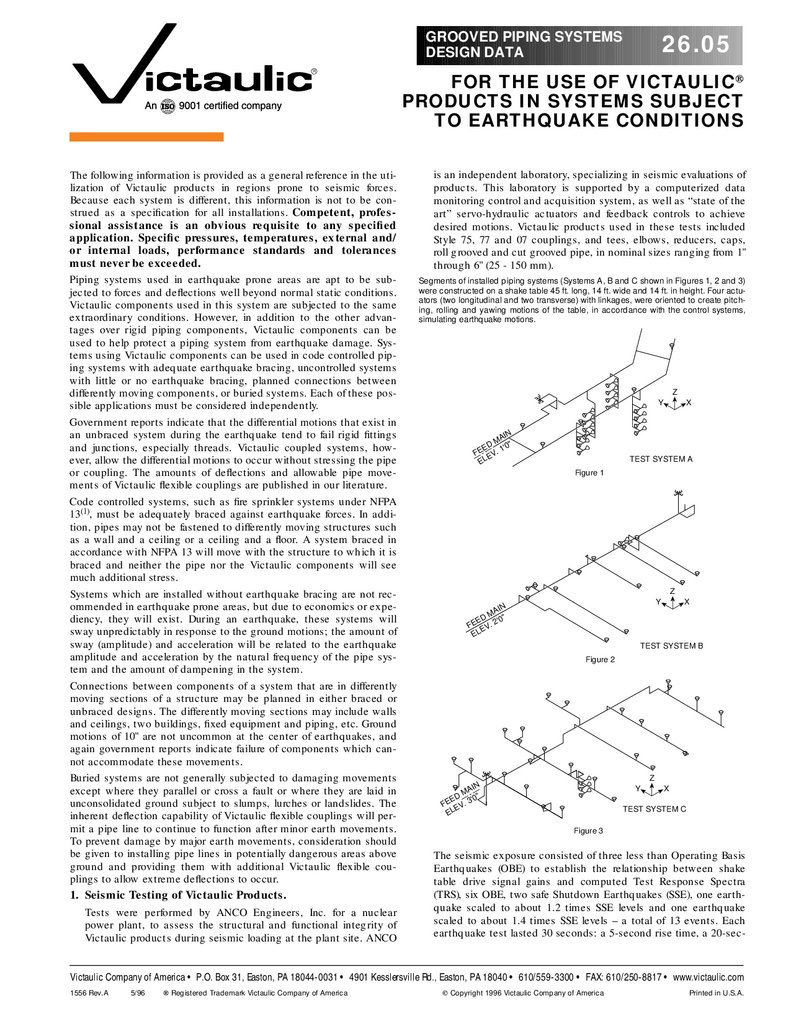
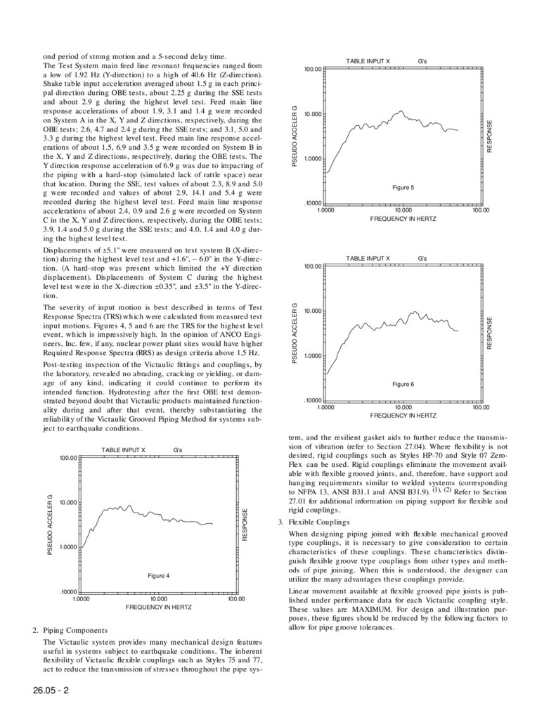
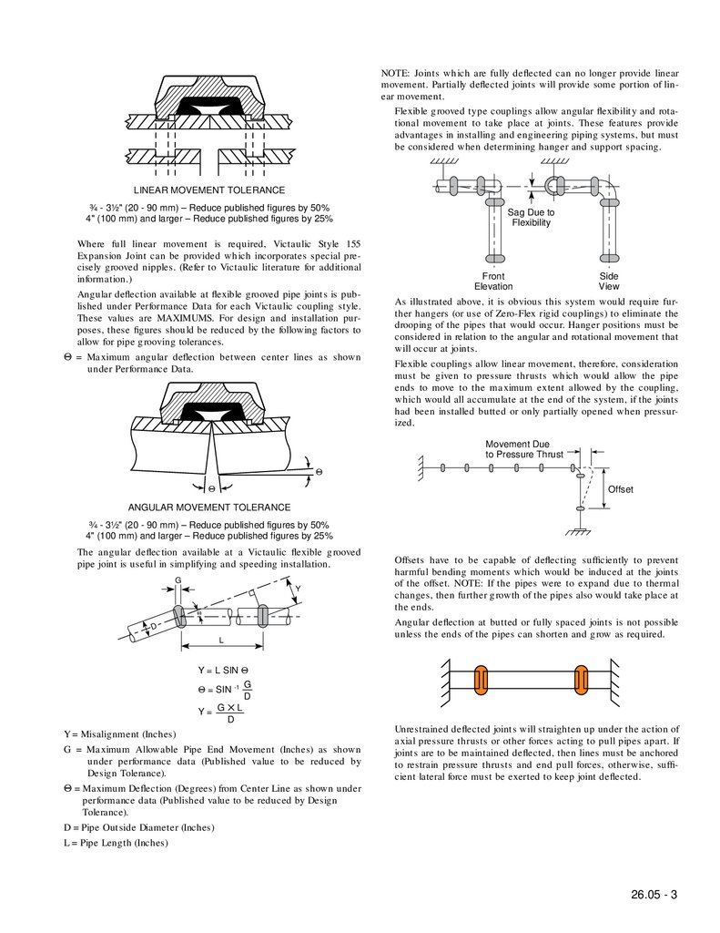
Segments of installed piping systems (Systems A, B and C shown in Figures 1, 2 and 3)
were constructed on a shake table 45 ft. long, 14 ft. wide and 14 ft. in height. Four actuators (two longitudinal and two transverse) with linkages, were oriented to create pitching, rolling and yawing motions of the table, in accordance with the control systems,
simulating earthquake motions.
Z
Y
IN
MA "
ED . 1'0
E
F EV
EL
X
TEST SYSTEM A
Figure 1
Z
Y
IN
MA
ED '0"
FE EV. 2
EL
X
TEST SYSTEM B
Figure 2
Z
IN
MA
ED . 3'0"
E
F EV
EL
Y
X
TEST SYSTEM C
Figure 3
The seismic exposure consisted of three less than Operating Basis
Earthquakes (OBE) to establish the relationship between shake
table drive signal gains and computed Test Response Spectra
(TRS), six OBE, two safe Shutdown Earthquakes (SSE), one earthquake scaled to about 1.2 times SSE levels and one earthquake
scaled to about 1.4 times SSE levels – a total of 13 events. Each
earthquake test lasted 30 seconds: a 5-second rise time, a 20-sec-
Victaulic Company of America • P.O. Box 31, Easton, PA 18044-0031 • 4901 Kesslersville Rd., Easton, PA 18040 • 610/559-3300 • FAX: 610/250-8817 • www.victaulic.com
1556 Rev.A
5/96
Ò Registered Trademark Victaulic Company of America
Ó Copyright 1996 Victaulic Company of America
Printed in U.S.A.
2.
TABLE INPUT XG's
10.000
RESPONSE
PSEUDO ACCELER G
100.00
1.0000
Figure 4
.10000
1.0000
10.000
FREQUENCY IN HERTZ
100.00
2. Piping Components
The Victaulic system provides many mechanical design features
useful in systems subject to earthquake conditions. The inherent
flexibility of Victaulic flexible couplings such as Styles 75 and 77,
act to reduce the transmission of stresses throughout the pipe sys-
26.05 - 2
TABLE INPUT X
G's
10.000
RESPONSE
PSEUDO ACCELER G
100.00
1.0000
Figure 5
.10000
1.0000
10.000
FREQUENCY IN HERTZ
TABLE INPUT X
100.00
G's
100.00
10.000
RESPONSE
PSEUDO ACCELER G
ond period of strong motion and a 5-second delay time.
The Test System main feed line resonant frequencies ranged from
a low of 1.92 Hz (Y-direction) to a high of 40.6 Hz (Z-direction).
Shake table input acceleration averaged about 1.5 g in each principal direction during OBE tests, about 2.25 g during the SSE tests
and about 2.9 g during the highest level test. Feed main line
response accelerations of about 1.9, 3.1 and 1.4 g were recorded
on System A in the X, Y and Z directions, respectively, during the
OBE tests; 2.6, 4.7 and 2.4 g during the SSE tests; and 3.1, 5.0 and
3.3 g during the highest level test. Feed main line response accelerations of about 1.5, 6.9 and 3.5 g were recorded on System B in
the X, Y and Z directions, respectively, during the OBE tests. The
Y direction response acceleration of 6.9 g was due to impacting of
the piping with a hard-stop (simulated lack of rattle space) near
that location. During the SSE, test values of about 2.3, 8.9 and 5.0
g were recorded and values of about 2.9, 14.1 and 5.4 g were
recorded during the highest level test. Feed main line response
accelerations of about 2.4, 0.9 and 2.6 g were recorded on System
C in the X, Y and Z directions, respectively, during the OBE tests;
3.9, 1.4 and 5.0 g during the SSE tests; and 4.0, 1.4 and 4.0 g during the highest level test.
Displacements of ±5.1" were measured on test system B (X-direction) during the highest level test and +1.6", – 6.0" in the Y-direction. (A hard-stop was present which limited the +Y direction
displacement). Displacements of System C during the highest
level test were in the X-direction ±0.35", and ±3.5" in the Y-direction.
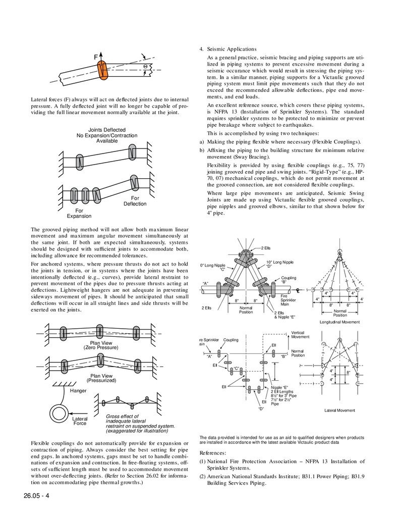
The severity of input motion is best described in terms of Test
Response Spectra (TRS) which were calculated from measured test
input motions. Figures 4, 5 and 6 are the TRS for the highest level
event, which is impressively high. In the opinion of ANCO Engineers, Inc. few, if any, nuclear power plant sites would have higher
Required Response Spectra (RRS) as design criteria above 1.5 Hz.
Post-testing inspection of the Victaulic fittings and couplings, by
the laboratory, revealed no abrading, cracking or yielding, or damage of any kind, indicating it could continue to perform its
intended function. Hydrotesting after the first OBE test demonstrated beyond doubt that Victaulic products maintained functionality during and after that event, thereby substantiating the
reliability of the Victaulic Grooved Piping Method for systems subject to earthquake conditions.
1.0000
Figure 6
.10000
1.0000
10.000
FREQUENCY IN HERTZ
100.00
tem, and the resilient gasket aids to further reduce the transmission of vibration (refer to Section 27.04). Where flexibility is not
desired, rigid couplings such as Styles HP-70 and Style 07 ZeroFlex can be used. Rigid couplings eliminate the movement available with flexible grooved joints, and, therefore, have support and
hanging requirements similar to welded systems (corresponding
to NFPA 13, ANSI B31.1 and ANSI B31.9). (1), (2) Refer to Section
27.01 for additional information on piping support for flexible and
rigid couplings.
3. Flexible Couplings
When designing piping joined with flexible mechanical grooved
type couplings, it is necessary to give consideration to certain
characteristics of these couplings. These characteristics distinguish flexible groove type couplings from other types and methods of pipe joining. When this is understood, the designer can
utilize the many advantages these couplings provide.
Linear movement available at flexible grooved pipe joints is published under performance data for each Victaulic coupling style.
These values are MAXIMUM. For design and illustration purposes, these figures should be reduced by the following factors to
allow for pipe groove tolerances.
3.
NOTE: Joints which are fully deflected can no longer provide linearmovement. Partially deflected joints will provide some portion of linear movement.
Flexible grooved type couplings allow angular flexibility and rotational movement to take place at joints. These features provide
advantages in installing and engineering piping systems, but must
be considered when determining hanger and support spacing.
LINEAR MOVEMENT TOLERANCE
³⁄₄ - 3¹⁄₂" (20 - 90 mm) – Reduce published figures by 50%
4" (100 mm) and larger – Reduce published figures by 25%
Where full linear movement is required, Victaulic Style 155
Expansion Joint can be provided which incorporates special precisely grooved nipples. (Refer to Victaulic literature for additional
information.)
Angular deflection available at flexible grooved pipe joints is published under Performance Data for each Victaulic coupling style.
These values are MAXIMUMS. For design and installation purposes, these figures should be reduced by the following factors to
allow for pipe grooving tolerances.
Q = Maximum angular deflection between center lines as shown
under Performance Data.
Sag Due to
Flexibility
Front
Elevation
Side
View
As illustrated above, it is obvious this system would require further hangers (or use of Zero-Flex rigid couplings) to eliminate the
drooping of the pipes that would occur. Hanger positions must be
considered in relation to the angular and rotational movement that
will occur at joints.
Flexible couplings allow linear movement, therefore, consideration
must be given to pressure thrusts which would allow the pipe
ends to move to the maximum extent allowed by the coupling,
which would all accumulate at the end of the system, if the joints
had been installed butted or only partially opened when pressurized.
Movement Due
to Pressure Thrust
Q
Q
Offset
ANGULAR MOVEMENT TOLERANCE
³⁄₄ - 3¹⁄₂" (20 - 90 mm) – Reduce published figures by 50%
4" (100 mm) and larger – Reduce published figures by 25%
The angular deflection available at a Victaulic flexible grooved
pipe joint is useful in simplifying and speeding installation.
G
Y
Q
D
L
Offsets have to be capable of deflecting sufficiently to prevent
harmful bending moments which would be induced at the joints
of the offset. NOTE: If the pipes were to expand due to thermal
changes, then further growth of the pipes also would take place at
the ends.
Angular deflection at butted or fully spaced joints is not possible
unless the ends of the pipes can shorten and grow as required.
Y = L SIN QŸ
Q = SIN -1 G
D
Y= G✕L
D
Y = Misalignment (Inches)
G = Maximum Allowable Pipe End Movement (Inches) as shown
under performance data (Published value to be reduced by
Design Tolerance).
Q = Maximum Deflection (Degrees) from Center Line as shown under
performance data (Published value to be reduced by Design
Tolerance).
D = Pipe Outside Diameter (Inches)
L = Pipe Length (Inches)
Unrestrained deflected joints will straighten up under the action of
axial pressure thrusts or other forces acting to pull pipes apart. If
joints are to be maintained deflected, then lines must be anchored
to restrain pressure thrusts and end pull forces, otherwise, sufficient lateral force must be exerted to keep joint deflected.
26.05 - 3
4.
FQ
Lateral forces (F) always will act on deflected joints due to internal
pressure. A fully deflected joint will no longer be capable of providing the full linear movement normally available at the joint.
Joints Deflected
No Expansion/Contraction
Available
For
Deflection
For
Expansion
The grooved piping method will not allow both maximum linear
movement and maximum angular movement simultaneously at
the same joint. If both are expected simultaneously, systems
should be designed with sufficient joints to accommodate both,
including allowance for recommended tolerances.
For anchored systems, where pressure thrusts do not act to hold
the joints in tension, or in systems where the joints have been
intentionally deflected (e.g., curves), provide lateral restraint to
prevent movement of the pipes due to pressure thrusts acting at
deflections. Lightweight hangers are not adequate in preventing
sideways movement of pipes. It should be anticipated that small
deflections will occur in all straight lines and side thrusts will be
exerted on the joints.
4. Seismic Applications
As a general practice, seismic bracing and piping supports are utilized in piping systems to prevent excessive movement during a
seismic occurance which would result in stressing the piping system. In a similar manner, piping supports for a Victaulic grooved
piping system must limit pipe movements such that they do not
exceed the recommended allowable deflections, pipe end movements, and end loads.
An excellent reference source, which covers these piping systems,
is NFPA 13 (Installation of Sprinkler Systems). The standard
requires sprinkler systems to be protected to minimize or prevent
pipe breakage where subject to earthquakes.
This is accomplished by using two techniques:
a) Making the piping flexible where necessary (Flexible Couplings).
b) Affixing the piping to the building structure for minimum relative
movement (Sway Bracing).
Flexibility is provided by using flexible couplings (e.g., 75, 77)
joining grooved end pipe and swing joints. “Rigid-Type” (e.g., HP70, 07) mechanical couplings, which do not permit movement at
the grooved connection, are not considered flexible couplings.
Where large pipe movements are anticipated, Seismic Swing
Joints are made up using Victaulic flexible grooved couplings,
pipe nipples and grooved elbows, similar to that shown below for
4" pipe.
2 Ells
10" Long Nipple
“D”
0" Long Nipple
“C”
Coupling
“B”
“A”
8"
2 Ells
Fire
Sprinkler
Main
8"
Normal
Position
4"
4"
4"
4"
8"
8"
Normal
Position
2 Ells
& Nipple “E”
Longitudinal Movement
Plan View
(Zero Pressure)
re Sprinkler
ain
Vertical
Movement
Coupling
Ell
“A”
“B”
Ell
Normal
Position
“C”
4"
Plan View
(Pressurized)
Ell
Hanger
Ell
“D”
Lateral
Force
Nipple “E”
2 Ell Lengths
8¹⁄₂" for 3" Pipe
7¹⁄₂" for 2¹⁄₂"
Pipe
Lateral Movement
Gross effect of
inadequate lateral
restraint on suspended system.
(exaggerated for illustration)
Flexible couplings do not automatically provide for expansion or
contraction of piping. Always consider the best setting for pipe
end gaps. In anchored systems, gaps must be set to handle combinations of expansion and contraction. In free-floating systems, offsets of sufficient length must be used to accommodate movement
without over-deflecting joints. (Refer to Section 26.02 for information on accommodating pipe thermal growths.)
26.05 - 4
8"
4"
The data provided is intended for use as an aid to qualified designers when products
are installed in accordance with the latest available Victaulic product data
References:
(1) National Fire Protection Association – NFPA 13 Installation of
Sprinkler Systems.
(2) American National Standards Institute; B31.1 Power Piping; B31.9
Building Services Piping.