


 Строительство
Похожие презентации:


")


The goal of this testing was to demonstrate the suitability of Victaulic Grooved Mechanical Couplings
1.
26.13DESIGN DATA – GROOVED PIPING SYSTEM
Seismic Testing Program
Test Summary
Victaulic in Seismic Conditions
Seismic Testing was completed on 4”/DN100, 8”/DN200, and 16”/
DN400 Victaulic grooved mechanical pipe couplings and fittings
installed on standard wall carbon steel pipe. The testing proved
that Victaulic couplings are most suitable for use on piping systems
subjected to earthquakes. The test program was developed in
accordance with an internationally recognized current shake table
standard for testing nonstructural building components. The piping
assemblies were subjected to input amplitudes of ±3”/76mm in both
x and y horizontal directions, input accelerations of up to 1.3g and
a frequency range of 1.3 to 33Hz. Braced rigid and flexible sections
performed flawlessly under the test conditions which saw peak
accelerations of the piping to be recorded at over 7g’s. The water filled
assemblies were pressurized to 200 psi/1375 kPa for the duration of all
tests and no pressure loss or leakage was noted during or after any of
the tests.
The use of Victaulic flexible grooved couplings in areas subject to
seismic events has been traced back to the early 1940’s where they
were used to provide stress relief at equipment connections. Since that
time grooved products have become a standard joining method due
to their unique design benefits in being able to provide both rigid and
flexible pipe joints based upon a specific system’s design requirements.
Victaulic products have had many years of successful performance in
areas that have experienced seismic events such that they have become
the standard method for joining pipe on many projects in seismic
areas. There have also been a number of in-house and third party tests
performed in order to qualify the performance capabilities of Victaulic
products when subjected to adverse conditions such as seismic events,
shipboard piping systems and high pressure cycling. The results of
these various tests have proven the reliability and integrity of Victaulic
products under these adverse conditions.
Victaulic Company
Purpose of Testing
Victaulic realized the need for state of the art testing on our products
in order to demonstrate conformance to new code requirements and
prove they provide a sustainable system that will withstand the forces
generated during a seismic event and maintain system integrity when
subjected to real time seismic events. Testing was designed to provide
analytical data in support of the successful “real-world” performance
during past earthquakes.
Piping or building damage occurs due to differential movement between
the pipe and the building; and at locations where the piping crosses
a building seismic joint, where piping crosses between two separate
structures, or piping is supported or fixed to independent support
structures within a building, (IE: supported from the roof truss then
drops into racks). The former is addressed, within a given “structural
area”, by fixing the pipe (seismically bracing) to the building structure
so it moves in concert with the building. Bracing and clearances must
be designed for the specified seismic accelerations and amplitudes
of movement. The latter is addressed, where piping crosses from one
“structural area” to another. Piping should be installed with a flexible
component (seismic isolation assembly) sufficient to accommodate
the differential movement that will occur between pipes that are joined
but supported from or anchored to different “seismic structures”. The
flexible element permits these structures and the piping attached to
each structure to move independently within the building, without
damaging each other, or other equipment, during the seismic event.
Victaulic, founded in 1925, is the world leader in mechanical pipe
joining systems. Victaulic introduced a radical concept in joining
pipe—a mechanical bolted coupling that would engage into grooves and
uses an elastomer gasket to seal the joint.
The grooved piping method, which dramatically reduces the amount of
installation time as compared to welding, threading or flanging is used
extensively in HVAC, plumbing, fire protection, mining, industrial utilities,
oilfield piping, plus water and wastewater systems.
Victaulic products are found in major landmarks and buildings the world
over. With the ability to provide both rigid and flexible joints the Victaulic
system provides design versatility not found on other types of pipe
joining systems
The goal of this testing was to demonstrate the suitability of Victaulic
Grooved Mechanical Couplings and Fittings to be used to install and
maintain operational integrity of piping systems during seismic events.
The test program was designed to show seismic performance in two
conditions sited above. First, testing was conducted to prove that
rigid or flexible Victaulic couplings installed on code compliant braced
piping will maintain full performance when subjected to seismic events.
Second, testing was conducted to confirm the ability of our flexible
couplings in seismic swing joints or in offset pipe configurations, to
provide sufficient freedom of movement in order to accommodate the
differential movement of pipe between structures or at building seismic
separation joints.
www.victaulic.com
VICTAULIC IS A REGISTERED TRADEMARK OF VICTAULIC COMPANY. © 2008 VICTAULIC COMPANY. ALL RIGHTS RESERVED.
REV_A
26.13_1
2.
26.13DESIGN DATA – GROOVED PIPING SYSTEM
Seismic Tests
ATLSS Testing Facility
The minimum response spectra specified in AC156 were based upon
the seismic design loads specified in the current building codes. The
2006 International Building Code (IBC) was used for this test program.
The IBC 2006 references seismic loads as specified in ASCE 7-05
“Minimum Design Loads for Buildings and Other Structures” by the
American Society of Civil Engineers. The design of the piping and other
nonstructural components was based on the equivalent static load
method, similar to that used for building design.
Test Configuration
Lehigh University’s ATLSS Lab, Advanced Technology for Large
Structural Systems a national engineering research center, was chosen
to perform the required testing. The ATLSS Center is a member of the
Network for Earthquake Engineering Simulation (NEES), established
by the US National Science Foundation as a national networked
collaboration of geographically-distributed, shared-use experimental
research equipment sites. The Lehigh NEES Equipment Site was
developed with the capabilities to perform real-time testing using
effective force method, pseudo-dynamic testing method, or the pseudodynamic hybrid testing method for the testing of large-scale structural
components, structural subassemblages, and superassemblages
under earthquake excitations. Thus it is well suited to perform and
analyze simulated real-time multi-direction earthquake effects on
piping systems. Victaulic and Lehigh consulted with an internationally
recognized designer and supplier of seismic bracing systems, who
provided the design support for the hanging and bracing of the pipe test
assemblies.
Test Requirements
A test configuration was developed that could accommodate a large
pipeline and impose the required motions. The tests required the
capability of imposing large accelerations, displacements and velocities
on the piping and couplings. A horizontal truss was designed to serve
as a rigid diaphragm or “building ceiling” from which the piping would
be supported. The seismic motion was imposed on this “ceiling” which
in turn was transferred to the piping. Three NEES actuators were used
to impose the seismic motion required in both the longitudinal and
transverse directions. To record all pertinent test data accelerometers,
displacement sensors, and strain gauges were strategically placed in
pre-determined locations to provide an accurate record of the testing
program.
The piping layout consisted of a 40’/ 12m run (consisting of two 20’/6m
pipe lengths) with a 90° elbow and then a 10’/3m run on either end,
all joined with Victaulic Style 07 or W07 rigid couplings. This section
of piping was seismically braced in accordance with standard industry
code requirements and was referred to as the “braced rigid zone”.
On each end of the “braced rigid zone” there was a “flexible zone”
comprised of a Victaulic seismic isolation assembly. These displacement
assemblies were then connected to the ATLSS reaction wall that allowed
no movement. Therefore, movement of the piping in the “rigid zone”
generated relative displacements in the seismic isolation assemblies.
Rigid Zone Piping
Flexible
Braced Rigid
The test program was developed in accordance with current shake table
testing standards. Artificial ground motions were developed for this test
program. These randomly generated ground motions were generated to
satisfy a specified minimum response spectra.
The ICC Evaluation Service, Inc. report AC156 “Acceptance Criteria
for Seismic Qualification by Shake-table Testing of Nonstructural
Components and Systems” was used to develop the testing protocol.
This document establishes the minimum requirements for shaketable tests of non-structural components which includes piping. This
document specifies a minimum response spectra that is derived from
the code specified nonstructural component design seismic load. The
response spectrum of the input motion to the shake testing was greater
than the minimum spectrum specified in AC156.
www.victaulic.com
VICTAULIC IS A REGISTERED TRADEMARK OF VICTAULIC COMPANY. © 2008 VICTAULIC COMPANY. ALL RIGHTS RESERVED. .
26.13_2
REV_A
3.
26.13DESIGN DATA – GROOVED PIPING SYSTEM
Seismic Tests
Seismic Swing Joint
4”/DN100 Test Assembly
Seismic Loop
8”/DN200 Test Assembly
Seismic Loop- Rigid/Flexible Zones
NORTH
FIXED CONNECTION
@ REACTION WALL
20’
16”/DN400 Test Assembly
SWING JOINT
(W/FLEXIBLE
COUPLINGS)
Z-TYPE OFFSET
(W/FLEXIBLE
COUPLINGS)
RIGID ZONE
10’
10’
VERTICAL RISER
RIGID COUPLINGS
40’
Two different seismic isolation assemblies were utilized, one on each
end of the “rigid zone”. One assembly was a Z-Type offset configuration
and the other was a seismic swing joint. Both of these configurations
used the deflection and rotational characteristics of Victaulic Styles
77 and W77 flexible couplings to accommodate the differential piping
movement between the “rigid zone” and the reaction wall.
www.victaulic.com
VICTAULIC IS A REGISTERED TRADEMARK OF VICTAULIC COMPANY. © 2008 VICTAULIC COMPANY. ALL RIGHTS RESERVED.
REV_A
26.13_3
4.
26.13DESIGN DATA – GROOVED PIPING SYSTEM
Seismic Tests
Three pipe sizes were selected for testing: 4”/DN100, 8”/DN200
and 16”/DN400. Each size was tested individually as a complete
layout. A number of tests were performed on each piping assembly
to demonstrate the ability of Victaulic couplings to handle a variety of
seismic demands. The same couplings and pipe were used for all three
tests. These tests included a static displacement test, sinusoidal sweep
test and shake tests. The piping was water filled and pressurized to 200
psi/1375 kPa throughout the duration of all tests.
The static displacement test subjected each assembly to ± 4”/102mm
of movement in both x and y horizontal directions. The sinusoidal sweep
test subjected each assembly to a sinusoidal acceleration record with a
frequency range from 1.3Hz to 33Hz. The shake tests subjected each
assembly to three levels of seismic motion. The maximum inputs during
the shake tests were ± 3”/76 mm of horizontal movement and 1.3g
acceleration.
Two additional tests were performed. The first involved the 8”/DN200
piping assembly. Following the shake tests, the rigid couplings were
replaced with flexible couplings and all tests performed again. The
second involved the 16”/DN400 piping assembly. Following the standard
program tests, a real-time multi-directional hybrid simulation of the
Northridge Earthquake was performed. This testing was performed in
order to study the response of the piping system installed in a three story
building subjected to a real earthquake. Two tests were performed during
Pipe
Accelerations- was
g
thisSize-In./mm
testing. First the assembly
subjected to ½ of the calculated
4"/100mm
6.51
amplitude of the Northridge Earthquake.7.70
Second, the assembly was
8"/200mm
16"/400mm
6.71
subjected
to
1.07
times
the
calculated
amplitude.
16"/400mm - Northridge Simulati
4.17
Test Results
Performance of the Victaulic couplings was excellent. There was no
evidence of any pipe joint leakage throughout all of the tests. The 200
psi/1375 kPa internal pressure was always maintained. The piping and
couplings exhibited a very robust behavior even after the failure of a large
number of seismic bracing elements.
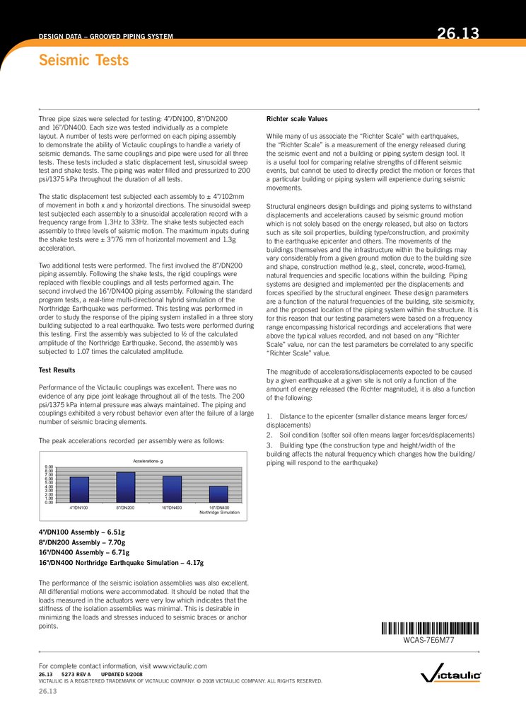
The peak accelerations recorded per assembly were as follows:
Accelerations- g
9.00
8.00
7.00
6.00
5.00
4.00
3.00
2.00
1.00
0.00
4"/DN100
8"/DN200
16"/DN400
Richter scale Values
While many of us associate the “Richter Scale” with earthquakes,
the “Richter Scale” is a measurement of the energy released during
the seismic event and not a building or piping system design tool. It
is a useful tool for comparing relative strengths of different seismic
events, but cannot be used to directly predict the motion or forces that
a particular building or piping system will experience during seismic
movements.
Structural engineers design buildings and piping systems to withstand
displacements and accelerations caused by seismic ground motion
which is not solely based on the energy released, but also on factors
such as site soil properties, building type/construction, and proximity
to the earthquake epicenter and others. The movements of the
buildings themselves and the infrastructure within the buildings may
vary considerably from a given ground motion due to the building size
and shape, construction method (e.g., steel, concrete, wood-frame),
natural frequencies and specific locations within the building. Piping
systems are designed and implemented per the displacements and
forces specified by the structural engineer. These design parameters
are a function of the natural frequencies of the building, site seismicity,
and the proposed location of the piping system within the structure. It is
for this reason that our testing parameters were based on a frequency
range encompassing historical recordings and accelerations that were
above the typical values recorded, and not based on any “Richter
Scale” value, nor can the test parameters be correlated to any specific
“Richter Scale” value.
The magnitude of accelerations/displacements expected to be caused
by a given earthquake at a given site is not only a function of the
amount of energy released (the Richter magnitude), it is also a function
of the following:
1. Distance to the epicenter (smaller distance means larger forces/
displacements)
2. Soil condition (softer soil often means larger forces/displacements)
3. Building type (the construction type and height/width of the
building affects the natural frequency which changes how the building/
piping will respond to the earthquake)
16"/DN400
Northridge Simulation
4"/DN100 Assembly – 6.51g
8"/DN200 Assembly – 7.70g
16"/DN400 Assembly – 6.71g
16"/DN400 Northridge Earthquake Simulation – 4.17g
The performance of the seismic isolation assemblies was also excellent.
All differential motions were accommodated. It should be noted that the
loads measured in the actuators were very low which indicates that the
stiffness of the isolation assemblies was minimal. This is desirable in
minimizing the loads and stresses induced to seismic braces or anchor
points.
WCAS-7E6M77
For complete contact information, visit www.victaulic.com
26.13
5273 REV A
UPDATED 5/2008
VICTAULIC IS A REGISTERED TRADEMARK OF VICTAULIC COMPANY. © 2008 VICTAULIC COMPANY. ALL RIGHTS RESERVED.
26.13