


 Медицина
Похожие презентации:


Nanoknife. Overview. Physician training
1.
Overview & UpdateDieter Klimke
May 3, 2011
2.
AgendaWhat is Nanoknife?
The system
Peri-Operative Considerations
Nanoknife Treatment Planning
Software Planning
Procedure, Tips & Tricks
Clinical Update
3.
WHAT IS NANOKNIFE?4.
NanoKnife® Therapy: What is It?• The NanoKnife® System is indicated for the surgical ablation of
soft tissue.
• An ablation procedure that uses low energy electrical pulses to
create defects in cell membranes.
• Uses high voltage, but low energy direct current (LEDC) – does not
rely on heat to ablate tissue.
• The process with which LEDC ablates soft tissue is known as
electroporation or irreversible electroporation (IRE).
• Well-suited for patients who have non-resectable soft tissue
disease near critical structures.
MLC 375 US Rev A
5.
How NanoKnife® Technology WorksThe function of a cell membrane
is to separate the intracellular and
extracellular milieu and to control
the transport processes between
the interior and the exterior of the
cell according to the cell needs.
Electroporation is a way to
increase cell membrane
permeability by subjecting it to an
electrical field.
MLC 375 US Rev A
6.
How The NanoKnife® System Works• Rapid series of short,
electrical pulses
• Low energy direct current
(LEDC)
• High voltage, but low energy
(Ablation zone)
• Does not rely on heat to
ablate tissue
• Defects (“pores”) created in
cell membrane
Notes:
• White area represents irreversible electroporation (i.e. ablation zone).
• Diagram developed from a mathematical model.
• Cell death occurs in the
ablation zone
7.
IrreversibleElectroporation
-
+
Reversible Electroporation
Note: Cell death occurs
in the pink zones.
-
+
-
+
Electroporation
No Electroporation
S. Dev, D. Rabussay, D. Widera, G. Hoffman, IEEE Trans. Plasma Sci, 2000
MLC 375 US Rev A
8.
NanoKnife® SystemClinical Advantages
Uses high voltage, low energy electrical pulses to achieve tissue effect
Does not rely on heat to ablate tissue
Poses no heat sink issues
Provides predictable zone of ablation
Allows real-time CT/US imaging of ablated zones
Provides ability to ablate soft tissue at or near critical structures (e.g.,
blood vessels, bile ducts, other tissues containing collagen/elastin)
Provides potential to spare critical structures – vasculature and ducts
remain intact
Ablated tissue removed by the body’s natural processes within weeks
(mimics natural cell death)
Patients report experiencing minimal to no post-procedural pain
MLC 375 US Rev A
9.
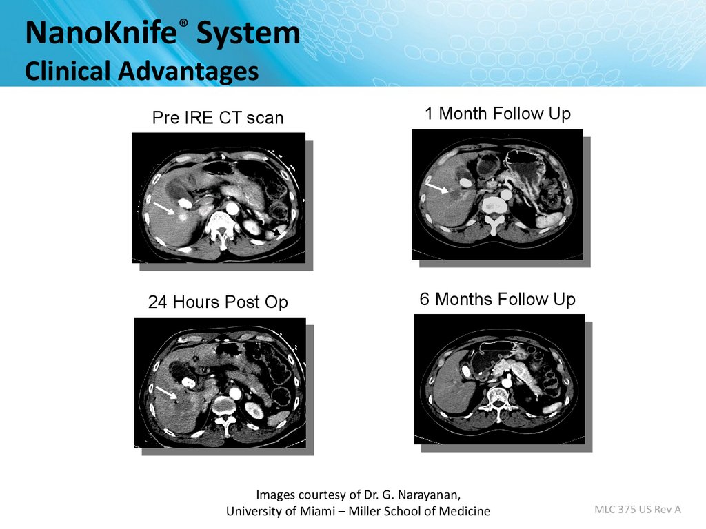
NanoKnife® SystemClinical Advantages
Pre IRE CT scan
1 Month Follow Up
24 Hours Post Op
6 Months Follow Up
Images courtesy of Dr. G. Narayanan,
University of Miami – Miller School of Medicine
MLC 375 US Rev A
10.
Predictable Zone of AblationNanoKnife lends itself very well to ablation planning
The mathematical model calculates the programmed ablation
zone which correlates to the hypo echoic image immediately
post-ablation and to gross pathology.
Mathematical model of
ablation zone
Ultrasound post-ablation
Gross pathology of ablation
Image Source: B Rubinsky et al, Technology in Cancer Research and Treatment, 2007
11.
Predictable and Reproducible Ablation1.5cm Probe Spacing
Two Electrodes, 15 mm space, 2500 volt
1.6cm by 2.6cm
Image Source: AngioDynamics pre-clinical research
porcine liver post-ablation.
12.
Visualized Under UltrasoundImmediately Post-Ablation
Image Source: AngioDynamics pre-clinical research porcine liver post-ablation.
13.
THE NANOKNIFE SYSTEM14.
NanoKnife® System• FDA 510(k) clearance for the surgical
ablation of soft tissue.
– It has not received clearance for the therapy or
treatment of any specific disease or condition.
• The NanoKnife System consists of the
generator (pictured at right), footswitch,
power cord, and a line of single-use
disposable electrodes. System has:
– Up to 6 outputs with programmable, automatic
switching between each output.
– USB port to download patient data.
• System also carries the CE mark.
15.
NanoKnife® System: the electrodesMonopolar Electrode
• Single Electrode
• Disposable
• 15 cm length
• 25 cm length
– In the event insufflation is used
– Obese patients
MLC 375 US Rev A
16.
NanoKnife® SystemMonopolar Electrode
Key Features
• 19 gauge needle with depth markings
• Echogenic needle surface
• Active electrode length adjustable in
0.5 cm increments from 0 – 4 cm
• Maximum insertion depth – 15 cm
• 8 foot connection cable
MLC 375 US Rev A
17.
Activation Probe18.
NanoKnife® System: Accusync• External synchronization device.
• The ECG Trigger Monitor
automatically detects the R Wave
(when energy is delivered) with
precision and reliability per its
manufacturer.
• A synchronization system that is
compatible with NanoKnife is
provided with each generator.
MLC 375 US Rev A
19.
Energy DeliverySynchronized (assume HR=60BPM)
90 pulses per ablation sequence – delivered in trains of 10 pulses.
100µS per pulse, ~1000 ms between pulses, 3500ms between trains.
Pulse amplitudes up to 3 kV @ 50 Amperes.
Delivery rate of 60/min, 1 energy pulse per R-Wave.
3kV
max
0
0
15
30
45
60
75
90
105
120
135
Seconds
1
2
R-R ~1000ms
3 …….
10
R-R ~1000ms
…….
100µs
100µs
MLC 375 US Rev A
20.
Why NanoKnife® Therapy?• Differentiate your institution from competing hospitals
• On the cutting edge of defining new treatments and applications
to expand patient care
–
–
–
–
Yet another reason why patients should come to your hospital
Leading efforts to integrate the NanoKnife procedure into clinical practice
Early adopter – will have more experience than others
Opportunity to speak and publish on the NanoKnife procedure – will
continue to build the institution’s reputation
• Market leadership in NanoKnife therapy to referral and patient
communities
– Drive patient referrals to your institution
– Patients seek out physicians who are published, speak, and have the most
experience with a particular therapy/procedure
MLC 375 US Rev A
21.
University of LouisvillePERI-OPERATIVE CONSIDERATIONS
22.
Objectives• NanoKnife Components
• Room Set Up
• Patient Set Up
• Anesthesia Considerations
• Treatment Planning
• Procedural Overview
23.
NanoKnife® System• NanoKnife System consists of the
Generator
Monopolar Electrodes
AccuSync 72 Trigger Monitor
24.
NANOKNIFE ROOM PREPARATION25.
Room Preparation• General anesthesia cart
– All monitoring & resuscitation equipment required for
general anesthesia per ASA guidelines
– This includes defibrillator
• NanoKnife generator & electrodes
– Position generator for optimal access to patient and
visibility of monitor to physician
• AccuSync system in place – hand leads to anesthesia
• For O.R. - Confirm availability of sterile ultra sound transducer
26.
Patient Set up• Position patient for optimal access
– Consider type of access; percutaneous, laparoscopic, open
– Consider gantry clearance
– Supine, prone, head first/feet first into gantry, etc
• Place AccuSync leads before draping
– Confirm R trigger indicators, compatible HR
– Compare to anesthesia’s ECG monitor
• Defib pads recommended
27.
Patient Set Up (Cont’d)• Physician to discuss with anesthesiologist
– Muscle blockade required during energy delivery
– Alert anesthesia 10 min before test pulse
– 0 to 1 twitches is optimal
– High energy pulses will interfere with ECG monitor
– BP and HR can be monitored during pulse generation by fast
pulse oximeter or arterial line
• Consider Foley
– initial cases may last ≥ 3 hours
28.
ECG Sync Device –Patient Lead Set Up
29.
AccuSync Set UpHold “Size” button
for 3 sec to get filter
menu.
Pink dots indicate
R-wave output.
Lead III is selected in
this example
Set delay to
zero.
Connect BNC cable to
BOTTOM jack labeled
“R-Trig”
30.
PROCEDURAL OVERVIEW31.
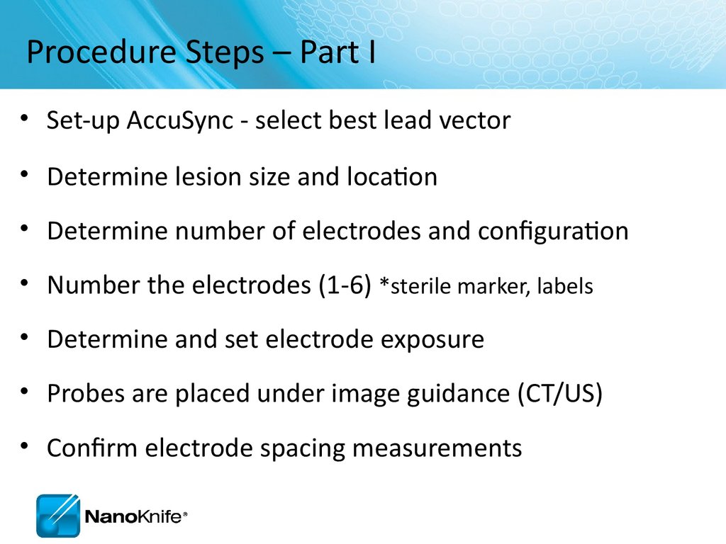
Procedure Steps – Part I• Set-up AccuSync - select best lead vector
• Determine lesion size and location
• Determine number of electrodes and configuration
• Number the electrodes (1-6) *sterile marker, labels
• Determine and set electrode exposure
• Probes are placed under image guidance (CT/US)
• Confirm electrode spacing measurements
32.
Procedure Steps – Part II• Update treatment planning software with actual inter-probe
measurements
– Re-position & Re-measure electrodes as needed
• Connect numbered electrodes to numbered generator outputs
• Review treatment parameters to ensure accuracy
– Very important! Especially if changing the pre-set
electrode numbering schema
Confirm 0 to 1 twitches
Physician delivers IRE energy
Monitor AccuSync display
Following completion of the procedure, review Pulse
Generation Treatment Parameters and Results Graph
33.
SOFTWARE PLANNING34.
Getting Started• Confirm the updated software is in place during start up
35.
Information Screen• There are five sections in the Information screen
1
2
3
4
5
36.
Patient InformationMandatory
information
Pop-up
Window
37.
Case InformationAuto populates
date
Key information
about the case
(e.g. type of
chemotherapy
they completed
etc. )
38.
Clinical DataEnter lesion type
Enter
dimensions
Select if the organ is prostate
39.
Tool BarExport Data
Change Language
40.
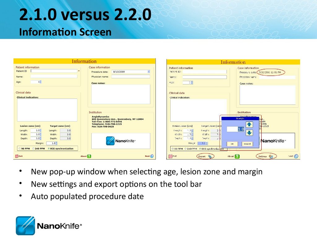
2.1.0 versus 2.2.0Information Screen
• New pop-up window when selecting age, lesion zone and margin
• New settings and export options on the tool bar
• Auto populated procedure date
41.
Objective:Accurately Correlate 3 Phases
Probes in Tissue
Needle 1
Needle 2
Needle 3
Probes on Grid Plot
Needle 4
Probes in Cross Sectional Image
42.
Labeling Length,Width, Depth
Width and Depth Orientation Change with Anatomical Approach
1.5 x 3.0 x 1.5 cm lesion in segment VIII
With long axis running axial (green line)
Length Craniocaudal—Yellow line
Depth
Width
Corresponds to probe orientation; probe axis
Lateral Probe Placement: D= Axial plane (green)
If D= Axial then W= AP
Anterior Probe Placement: D= AP axis (red)
IF D= AP then W= Axial
43.
NanoKnife Treatment PlanningEstimate Number of Probes...
Based on longest axis of lesion
3 probe array : 1- 1.2 cm lesion + 1 cm margin
4 probe array: 1.3-1.7 cm lesion + 1 cm margin
4 probe array: 1.8-2.0 cm lesion + (<1cm margin)
5 probe array: 1.8-2.0 cm lesion + 1cm margin
6 probe pentagonal array: 2.0- 2.5 cm lesion (0.9 margin)
6 probe rectangular array or “chevron” shaped array
44.
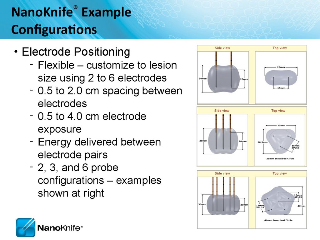
NanoKnife® ExampleConfigurations
• Electrode Positioning
‐ Flexible – customize to lesion
size using 2 to 6 electrodes
‐ 0.5 to 2.0 cm spacing between
electrodes
‐ 0.5 to 4.0 cm electrode
exposure
‐ Energy delivered between
electrode pairs
‐ 2, 3, and 6 probe
configurations – examples
shown at right
45.
Probe Selection Screen46.
Probe Selection ScreenActivator
probe
47.
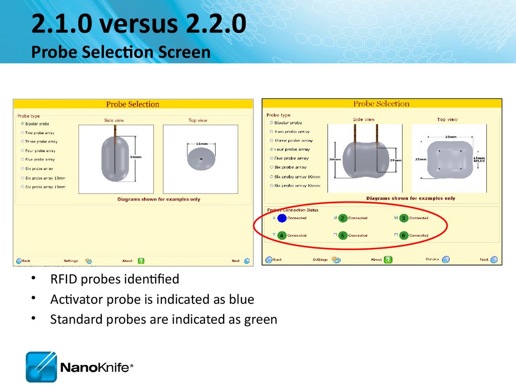
2.1.0 versus 2.2.0Probe Selection Screen
• RFID probes identified
• Activator probe is indicated as blue
• Standard probes are indicated as green
48.
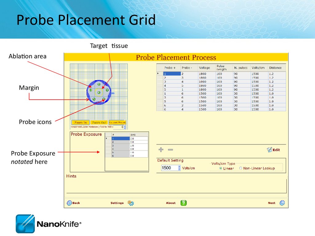
Probe Placement GridTarget tissue
Ablation area
Margin
Probe icons
Probe Exposure
notated here
49.
Orient Grid toAnatomical Approach
Anterior Probe Placement into 1.5 x 3.0 x 1.5 lesion
Head
1
2
Right
4
3
Depth = AP axis (front to back)
• Not an active value in grid model; only notated as “probe exposure”
Ablation with 4 electrodes in this orientation has local miss.
Left
50.
Orient Grid toAnatomical Approach
Lateral Probe Placement 1.5 x 3.0 x 1.5 lesion
Head
1
4
Ant.
2
3
Depth = Axial (Pt’s right to left/side to side)
• Not an active value in grid model; only notated as “probe
exposure”
• Probe exposure and pull backs address this dimension
4 electrodes ablates the lesion in 2 steps with 1 pull back.
Post.
51.
Probe Placement Process Screen2
1
3
4
5
52.
Probe Placement GridTarget tissue
(yellow)
Ablation area (gray)
Margin (blue)
Skipped Ablation
Probes
Fiducials
53.
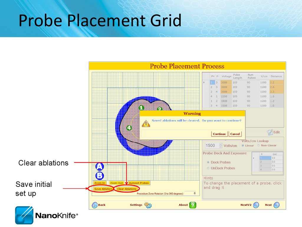
Probe Placement GridClear ablations
Save initial
set up
54.
Ablation SpreadsheetAllows the
user to
add/remov
e pulse
sequence
Values may
be changed
Enter probe
distances and
have them
automatically
placed on the
grid
55.
Adjusting VoltageChange
setting to
obtain
required
Volts/cm
Select if organ
is prostate
56.
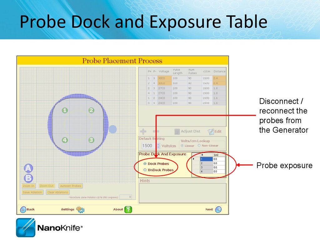
Probe Dock and Exposure TableDisconnect /
reconnect the
probes from
the Generator
Probe exposure
57.
Hint BoxHints box
provides
additional
instructions
58.
2.1.0 versus 2.2.0Probe Placement Screen
Probe Placement Grid is larger
Skipped lesions identified
Overlapping Ablation saved
Probe Distance Adjuster included
59.
Pulse Generation Screen• Where the ablation is delivered
Prepares,
controls, and
runs the ablation
delivery.
60.
Run SectionIf unsuccessful, the system will guide the user to check
the probe connections to ensure they are connected.
61.
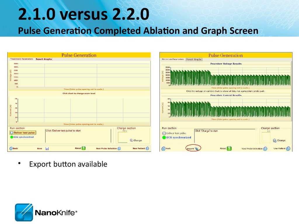
2.1.0 versus 2.2.0Pulse Generation Screen
• Different progress bar
• Export button available
62.
Ablation Delivery Completed63.
2.1.0 versus 2.2.0Pulse Generation Completed Ablation and Graph Screen
• Export button available
64.
Pulse Generation screenConfirm level of neuromuscular blockade now
Prepares, controls,
runs the ablation
delivery.
65.
Run SectionIf unsuccessful, the system will guide the user to check the probe
connections to ensure they are connected.
66.
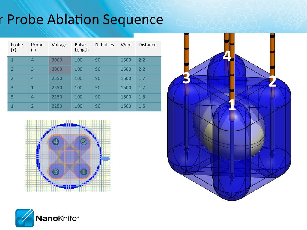
r Probe Ablation SequenceProbe
(+)
Probe
(-)
Voltage
Pulse
Length
N. Pulses
V/cm
Distance
1
4
3000
100
90
1500
2.2
2
3
3000
100
90
1500
2.2
2
4
2550
100
90
1500
1.7
3
1
2550
100
90
1500
1.7
3
4
2250
100
90
1500
1.5
1
2
2250
100
90
1500
1.5
4
3
2
1
67.
e Generation Completed68.
View Results Graph69.
NANOKNIFE TREATMENT PLANNING –PRACTICAL CONSIDERATIONS
USING 2.1.0 LESION ESTIMATOR
For Training Purpose Only- Not For Dissemination to Customers
70.
The StartTarget organs
–
–
–
–
Liver
Pancreas
Lung
Kidney
Manageable starting points
Endophytic lesions ≤ 2cm
Single probe groupings initially
Possibility to overlap later as user becomes established
For Training Purpose Only- Not For Dissemination to Customers
71.
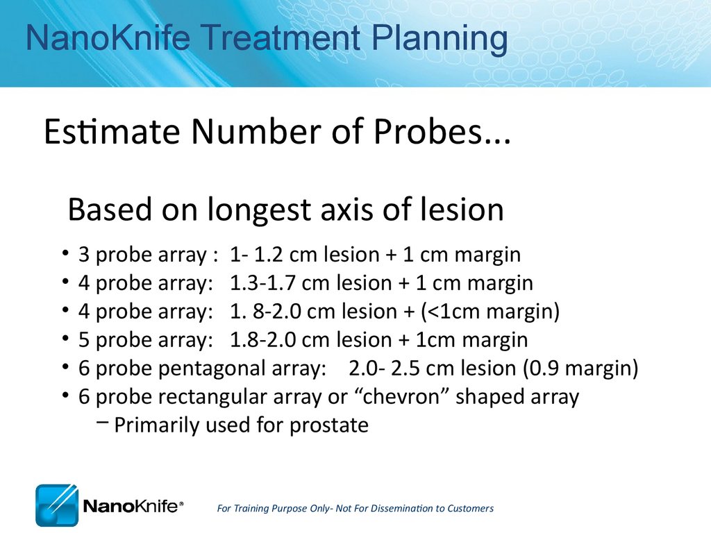
NanoKnife Treatment PlanningEstimate Number of Probes...
Based on longest axis of lesion
3 probe array : 1- 1.2 cm lesion + 1 cm margin
4 probe array: 1.3-1.7 cm lesion + 1 cm margin
4 probe array: 1. 8-2.0 cm lesion + (<1cm margin)
5 probe array: 1.8-2.0 cm lesion + 1cm margin
6 probe pentagonal array: 2.0- 2.5 cm lesion (0.9 margin)
6 probe rectangular array or “chevron” shaped array
– Primarily used for prostate
For Training Purpose Only- Not For Dissemination to Customers
72.
Optimum Electrode Placement• Keep electrodes parallel
• Avoid convergence
– Tips are closer together
• Avoid divergence
– Tips are further apart
---------
1.7 cm
-----
1.2 cm
----
1.2 cm
-------
1.7 cm
• Equal penetration depth
– Probe handles should be at same level
– Can adjust exposure while in tissue
• 1-2 mm from critical structures
For Training Purpose Only- Not For Dissemination to Customers
73.
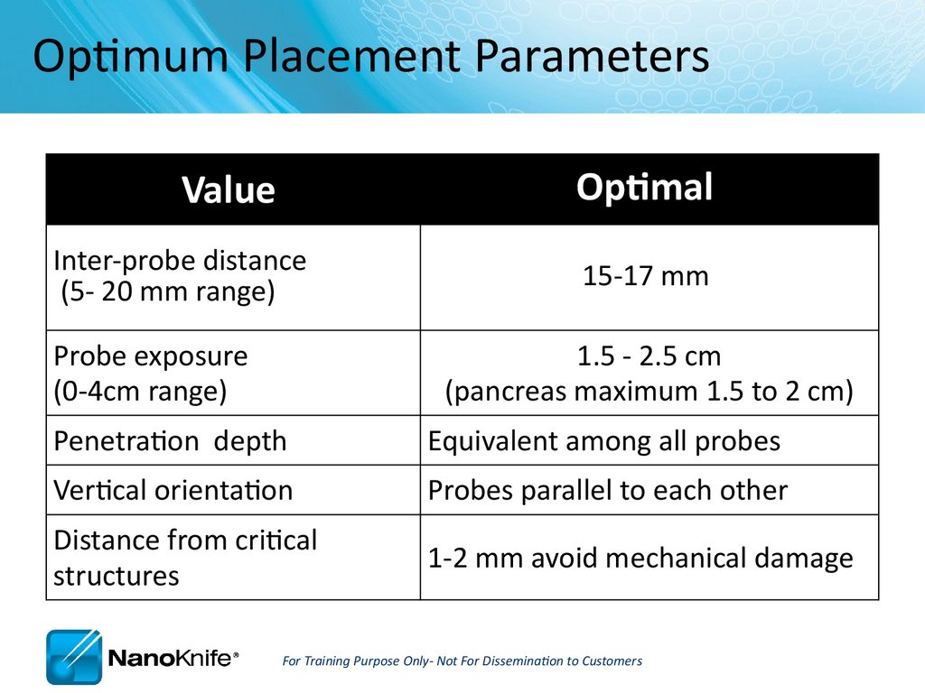
Optimum Placement ParametersOptimal
Value
Inter-probe distance
(5- 20 mm range)
Probe exposure
(0-4cm range)
15-17 mm
1.5 - 2.5 cm
(pancreas maximum 1.5 to 2 cm)
Penetration depth
Equivalent among all probes
Vertical orientation
Probes parallel to each other
Distance from critical
structures
1-2 mm avoid mechanical damage
For Training Purpose Only- Not For Dissemination to Customers
74.
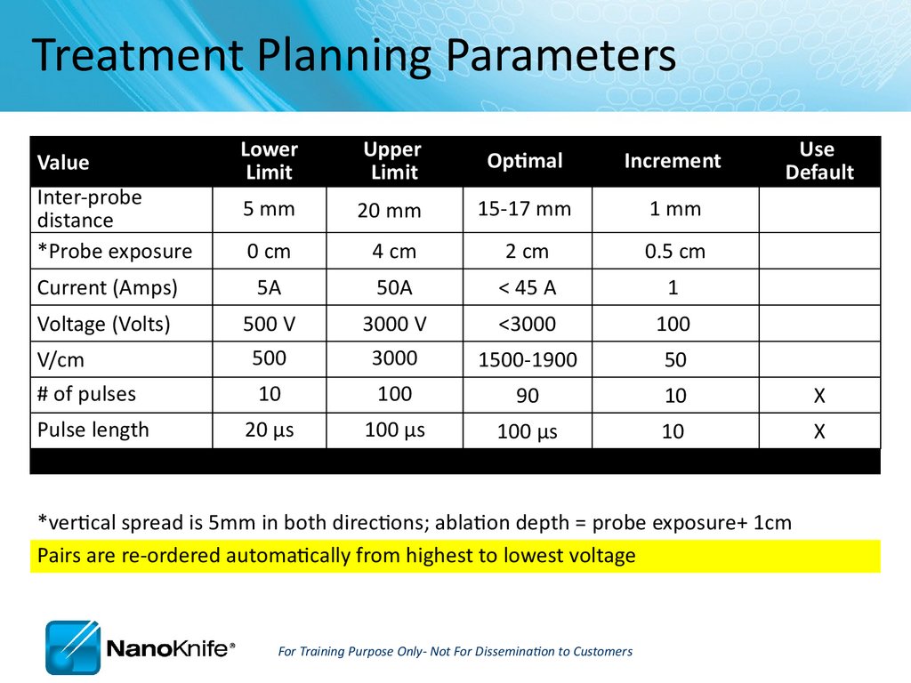
Treatment Planning ParametersLower
Limit
Upper
Limit
Optimal
Increment
5 mm
20 mm
15-17 mm
1 mm
0 cm
4 cm
2 cm
0.5 cm
Current (Amps)
5A
50A
< 45 A
1
Voltage (Volts)
500 V
3000 V
<3000
100
500
3000
1500-1900
50
10
100
90
10
X
20 µs
100 µs
100 µs
10
X
Value
Inter-probe
distance
*Probe exposure
V/cm
# of pulses
Pulse length
Use
Default
*vertical spread is 5mm in both directions; ablation depth = probe exposure+ 1cm
Pairs are re-ordered automatically from highest to lowest voltage
For Training Purpose Only- Not For Dissemination to Customers
75.
Relative Indicators of ElectroporationHow can you tell if you got an effective treatment?
Short answer:
There are no certain indicators
other than pathology.
There are relative indicators
–
–
–
–
–
–
–
Hypo echoic image (immediately)
Hyperchoic image after 24 hours
During treatment, tissue density changes; “softens”
Current outputs increase as tissue becomes electroporated
Saw tooth current output graph trends up from left to right
Contrast enhanced CT immediately after
At least 80 pulses completed
For Training Purpose Only- Not For Dissemination to Customers
76.
High Current and Popping• Hydrolysis is the dissociation of water molecules
– A ‘muffled’ sound during pulses is common and benign
– Loud popping may require adjustment
• Probes may be arcing or outside organ capsule
• Common in cystic, fluid-filled areas i.e. kidney
• High current and possibly heating
• Recommended adjustments
–
–
–
–
Reposition probe tips within organ capsule
Decrease exposed electrode
Retract probe(s) to a shallower penetration depth
Decrease amplitude V/cm
For Training Purpose Only- Not For Dissemination to Customers
77.
Trouble shooting- first line assessmentIt’s always a good idea to…
RE-IMAGE when probe placement,
inter-probe distance or relative
ablation zone is in question.
78.
Organ-Specific Considerations• Liver
– Good starting place
– Possibility for combined treatment on larger lesions
(IRE at/near critical structures +
thermal, embolic or chemical)
– 2.5 cm max electrode exposure
– Bile very conductive; high current
• Pancreas
– Risk to benefit ratio favors IRE
– Pancreatitis is probable but manageable
– Limit punctures when possible
For Training Purpose Only- Not For Dissemination to Customers
79.
Organ-Specific Considerations• Kidney
–
–
–
–
Very conductive ( draws 20-23 Amps)
2-2.5 max probe exposure
Pulses into adrenal gland can cause elevated BP > 200
Circuits across collecting system create high current, smaller than expected
ablation
– Dbl -J stents have been placed (by Thompson, Pech) to maintain ureteral
patency
• Lung
–
–
–
–
–
–
Poor conductivity in normal lung
CT imaging preferred
Place probes into (solid) lesion at peripheral edges for best conductivity
Pneumothorax is common
Multiple punctures increase pneumo risk
Atelectatic lung more conductive than aerated lung
For Training Purpose Only- Not For Dissemination to Customers
80.
Procedure Tips, Tricks, and TroubleshootingSeptember 16, 2010
81.
Learning ObjectivesNanoKnife Set-Up
AccuSync 72 Set-Up
ECG Synchronized Pulse Delivery
Proper Sync Function
ECG Sync Device Lead Set-Up
Signs of Saturation
Other ECG Sync Problems
Trouble Shooting
Physics (Voltage/Current/Resistance)
Optimal Parameters
For Training Purpose Only- Not For Dissemination to Customers
82.
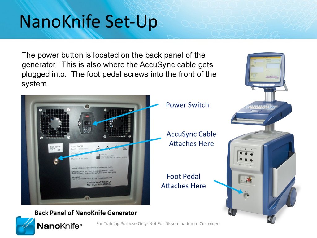
NanoKnife Set-UpThe power button is located on the back panel of the
generator. This is also where the AccuSync cable gets
plugged into. The foot pedal screws into the front of the
system.
Power Switch
AccuSync Cable
Attaches Here
Foot Pedal
Attaches Here
Back Panel of NanoKnife Generator
For Training Purpose Only- Not For Dissemination to Customers
83.
Demo ModeIn the event the system boots in demo mode, check
to make sure the STOP button is not depressed.
The “Button Status” light should be on (Green)
For Training Purpose Only- Not For Dissemination to Customers
84.
AccuSync Set-UpCable Connected to
BOTTOM jack labeled
“R-Trig”
Power Switch
Power Cord
Lead Pair
Sync Marks
Patient Leads
For Training Purpose Only- Not For Dissemination to Customers
85.
AccuSync Set UpRecommend attaching
AccuSync Leads before
preparing sterile field
AccuSync Pad Placement Diagram
For Training Purpose Only- Not For Dissemination to Customers
86.
Software with AccuSync• The generator will start in ECG Synchronization mode
(default setting)
• You won’t be able to leave the patient screen until the
sync signal is connected and consistent
For Training Purpose Only- Not For Dissemination to Customers
87.
AccuSync Tips• Select 2-3 leads with the Biggest R wave and smallest T wave
Maximize
Minimize
• Tip: Use same lead as anesthesiologist (I, II, III, aVF, aVL, aVR, or C)
• They will most likely choose the best waveform.
• Right before Test Pulse, Verify that the:
• Sync pulses are on R wave—not the p-wave
Not Here
Here
• Tip: No Defect should appear in the Arterial Pressure
For Training Purpose Only- Not For Dissemination to Customers
88.
ECG Synchronized Pulse DeliveryLEDC Pulse
Vulnerable
Period
Refractory
Period
50ms (0.05 sec)
Sync device (e.g. AccuSync 72) senses the rising slope of the R-wave,
and sends a signal to the NanoKnife. The NanoKnife waits 50
milliseconds (.05 sec) and delivers 1 LEDC pulse. The LEDC pulse is
delivered during (or just before) the refractory period.
For Training Purpose Only- Not For Dissemination to Customers
89.
No SaturationFor Training Purpose Only- Not For Dissemination to Customers
90.
Heavy SaturationRecommend changing lead pair to resolve saturation
For Training Purpose Only- Not For Dissemination to Customers
91.
Trouble Shooting SaturationRemove the BNC Cable from the back of the AccuSync Box
For Training Purpose Only- Not For Dissemination to Customers
92.
Trouble Shooting SaturationWarning Message will Appear on Generator Screen
For Training Purpose Only- Not For Dissemination to Customers
93.
Trouble Shooting SaturationAfter 15 seconds, a new window appears giving you 120 seconds before the
procedure self aborts
For Training Purpose Only- Not For Dissemination to Customers
94.
Trouble Shooting SaturationPress the “MAIN” button. (just tap it, don’t hold it down)
For Training Purpose Only- Not For Dissemination to Customers
95.
Trouble Shooting SaturationYou will see the “LEAD” field highlighted, if it’s not, keep
pressing main until you see “LEAD” highlighted.
For Training Purpose Only- Not For Dissemination to Customers
96.
Trouble Shooting SaturationThen press the “+” or “-” arrow to change the lead pair.
(Remember, just tap it, don’t hold it down)
For Training Purpose Only- Not For Dissemination to Customers
97.
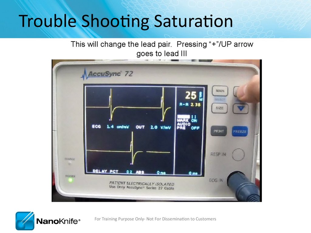
Trouble Shooting SaturationThis will change the lead pair. Pressing “+”/UP arrow
goes to lead III
For Training Purpose Only- Not For Dissemination to Customers
98.
Trouble Shooting SaturationAfter a second or two, you can start to see nice waveform
For Training Purpose Only- Not For Dissemination to Customers
99.
Trouble Shooting SaturationReattach the BNC Cable to the back of the AccuSync Box
After verifying proper waveform
For Training Purpose Only- Not For Dissemination to Customers
100.
Trouble Shooting SaturationClicking Resume will continue the treatment from where it left off.
For Training Purpose Only- Not For Dissemination to Customers
101.
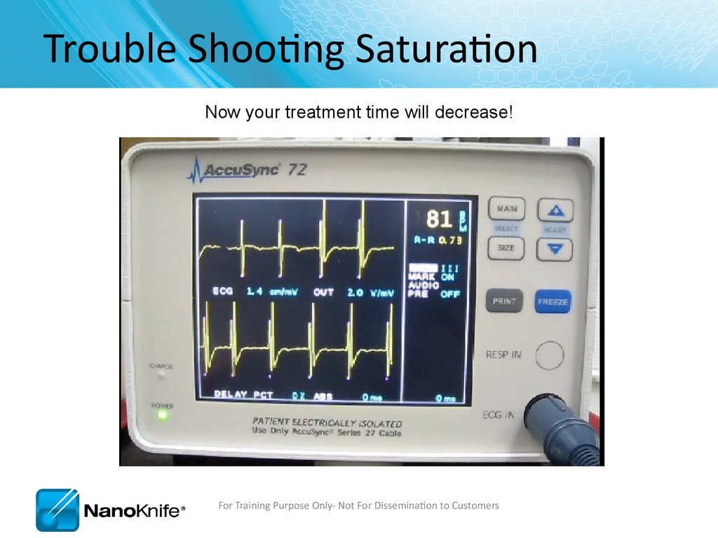
Trouble Shooting SaturationNow your treatment time will decrease!
For Training Purpose Only- Not For Dissemination to Customers
102.
AccuSync TroubleshootingProblem
Solution
NanoKnife does not see sync
signals during setup.
(“Sync Lost” alarm)
• Check that the BNC cable on the back of the AccuSync is
connected to “R-Trig” (and not ‘ECG out’).
• Is the cable connected to the NanoKnife?
“Sync Lost” alarm during
treatment
• Did an ECG lead fall off? (“lead off” on sync device display)
• Sync device missing R-waves after LEDC pulse. Switch leads.
“Noisy ECG”
AccuSync saturates
• Change lead setting.
• Move ECG buttons further from treatment area.
• Use different button locations.
Anesthesia Monitor ECG
interference
Monitor arterial pressure wave or monitor fast response SPO2 wave.
Recommend Stopping pulse delivery if BP drops.
Can’t get aVF, aVR, or aVL
Check connections on RL and V1 leads. These 2 can locate anywhere
on the body (including siamesed w/ RA, LA, or LL).
High HR > 120 bpm
Move AccuSync Cables away from Generator Panel Mount
Move bovie pencil away from patient.
Switch leads on AccuSync (II, III, and aVf seem to work best).
Plug NanoKnife into a different circuit.
Check AccuSync filter is set to 60Hz (hold size button 3 sec)
For Training Purpose Only- Not For Dissemination to Customers
103.
NanoKnife TroubleshootingProblem
Solution
Starts up in
Demo Mode
• Reset red Emergency Stop button on front of console.
• Green light indicates Emergency Button is Reset
NanoKnife Does not
turn on (plugged in).
• Replace BOTH Fuses. Quick ‘Off/On’ cycling can blow the fuses. ‘Off /
Wait ~5 sec / On’ prevents blown fuses. Carry spare fuses!
Can not leave the
patient info screen
• Must enter a patient ID Number (Upper left of screen).
Can not arm, or can not
activate
• Is the foot pedal plugged in? Wiggle cord at connector. Possible
faulty foot pedal.
“Failure to Charge /
Discharge”
• Go back to probe layout screen, forward to delivery screen. If that does
not work, then shut down and restart.
USBFPGA communication
error
• Shut down and restart. Unit will prompt shutdown.
For Training Purpose Only- Not For Dissemination to Customers
104.
Procedure TroubleshootingProblem
Solution
Loud popping during
pulse delivery; may also
have over-current alarm.
** Stop ablation**
• Reduce exposed electrode and treat at 2 depths.
• Reduce treatment voltage. Try Reducing Electrode Exposure First
• Is the entire exposed electrode INSIDE the target tissue?
Current too low
• Are electrodes plugged into the generator and in the right number
socket?
• Low current may be normal if low voltage (<1500V) and short probe
exposure (<1.5 cm).
• Normal in lung.
Current too high
Reduce probe exposure, perform duplicate treatment at 2 depths, reposition probes further apart, shorten pulse to 70usec.
Treatment aborted due
to high current
Repeat aborted pulse trains at a lower voltage; OR
Reduce probe exposure, repeat aborted trains at 2 depths.
Repeat pulse delivery until 70-90 pulses have been delivered.
Patient movement
Suggest muscle blockade similar to that used for a thoracotomy.
Paralytic half life is usually 20 min. Additional dose may be needed prior
to LEDC pulse delivery
For Training Purpose Only- Not For Dissemination to Customers
105.
Procedure TroubleshootingProblem
Solution
Probes are migrating out
during pulse delivery
** Stop ablation**
• Check to ensure cables are clamped to sterile drape to reduce weight
Probes are migrating
inwards during pulse
delivery
• Is the patient fully paralyzed? 0-1 twitches?
• Use a tuohy borst adapter or steri-strip flag to prevent probe
migration
Missing ablations in
lesion estimation
software
Verify the treatment table is accurate, pulses will be delivered according to
table, not image. You can select different probe icons to visualize the
missing lesion, usually this makes another pair disappear.
Charge “flutters” prior
to test pulse
Press back, then forward. If this does not work, change configuration to
include 1 extra probe, add treatment pair including extra probe, set
spacing > 2cm from other probes, reduce pulse for that one pair to 10, it
will result in low current warning, proceed with treatment.
Narrow pulse widths on
output graph
IGBT2 Calibration Error, Service Required. Operate in low current range to
get through case (i.e. reduce probe exposure).
Pulse delivery stalls midtreatment
Must abort treatment, treat like any other high current condition. (e.g.
reduce electrode exposure, reduce pulse width, reduce voltage)
For Training Purpose Only- Not For Dissemination to Customers
106.
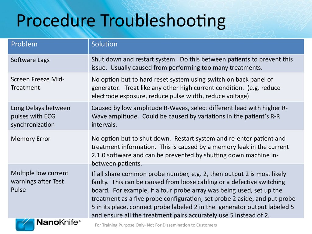
Procedure TroubleshootingProblem
Solution
Software Lags
Shut down and restart system. Do this between patients to prevent this
issue. Usually caused from performing too many treatments.
Screen Freeze MidTreatment
No option but to hard reset system using switch on back panel of
generator. Treat like any other high current condition. (e.g. reduce
electrode exposure, reduce pulse width, reduce voltage)
Long Delays between
pulses with ECG
synchronization
Caused by low amplitude R-Waves, select different lead with higher RWave amplitude. Could be caused by variations in the patient’s R-R
intervals.
Memory Error
No option but to shut down. Restart system and re-enter patient and
treatment information. This is caused by a memory leak in the current
2.1.0 software and can be prevented by shutting down machine inbetween patients.
If all share common probe number, e.g. 2, then output 2 is most likely
faulty. This can be caused from loose cabling or a defective switching
board. For example, if a four probe array was being used, set up the
treatment as a five probe configuration, set probe 2 aside, and put probe
5 in its place, connect probe labeled 2 in the generator output labeled 5
and ensure all the treatment pairs accurately use 5 instead of 2.
Multiple low current
warnings after Test
Pulse
For Training Purpose Only- Not For Dissemination to Customers
107.
Ohms Law V=IR• V= Voltage (Volts) – “The Input”
• R = Resistance (Ohms) - “Tissue Dependent”
• I = Current (Amps) – “The Output”
High HIGHER
Resistance resistance
• Lung has
HIGHER
(Insulator/Dielectric)
Low Resistance
(Conductive)
• Connective
Air
Metals
(Copper/Gold)
Tissue has HIGHER
resistance
Plastics (Polyimide/Silicone)
Water (Saline)
Elastin & Collagen
Urine
• Urine Non-Metals
has LOWER resistance Bile
• Electroporated Tissue has LOWER
LOWER resistance
For Training Purpose Only- Not For Dissemination to Customers
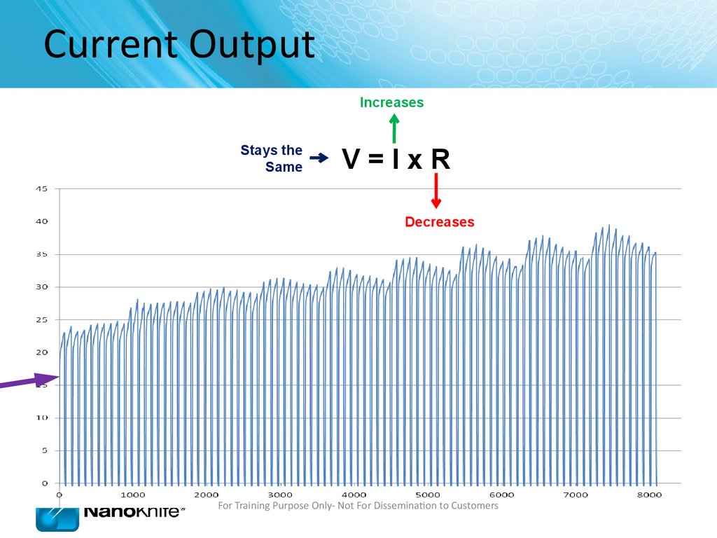
108.
Current OutputIncreases
Stays the
Same
V=IxR
Decreases
For Training Purpose Only- Not For Dissemination to Customers
109.
Current OutputFor Training Purpose Only- Not For Dissemination to Customers
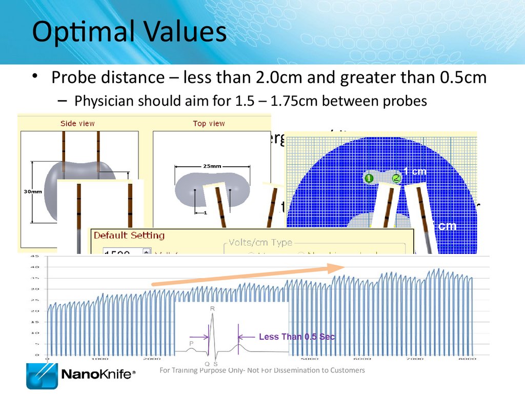
110.
Optimal Values• Probe distance – less than 2.0cm and greater than 0.5cm
– Physician should aim for 1.5 – 1.75cm between probes
• Parallel probes – avoid convergence/divergence
• Voltage – 1500 V/cm
1 cm
• Current- rising slope of current graph is a good indicator
1.5 cm
of effective treatment
• AccuSync works best when HR is between 50 – 70 bpm
and Q-T interval is less than 0.5 sec during
treatment
3 cm
GOOD
BAD
Less Than 0.5 Sec
For Training Purpose Only- Not For Dissemination to Customers
BAD
111.
Review Questions1.
What options are available to solve an over-current condition?
Reduce Probe Exposure / Reduce Pulse Length (70 µsec) / Reduce Voltage
2.
How do you solve AccuSync saturation?
Change Lead Pair (a.k.a. Vector) / Move Buttons Further from Treatment Area
3.
What do you check if the NanoKnife does not recognize a sync signal?
BNC Cable is connected to “R-Trig” / HR below 120 bpm / Change Lead Pair
4.
How can you tell if AccuSync is sending signals?
Triggering is indicated by pink marks on AccuSync Display Monitor
5.
What can cause low current errors?
Probes too far apart / Short Electrode Exposure / Low Input Voltage / Probe Not Connected
For Training Purpose Only- Not For Dissemination to Customers
112.
Highlights• Make sure:
• BNC Cable is Attached to “R Trig”
• Pink Marks Indicates Proper Sync Output
• The Generator has ECG Sync Enabled (default setting)
• Select lead with the Biggest R wave and smallest T wave
• Recommend attaching AccuSync Leads before preparing sterile field
• Saturation can be corrected:
• Change lead setting.
• Move ECG buttons further from treatment area.
• Use different button locations.
• V=IxR
• Trouble Shooting
• Optimal Parameters
For Training Purpose Only- Not For Dissemination to Customers
113.
Thank youFor Training Purpose Only- Not For Dissemination to Customers