
 Информатика
 Программное обеспечение
Похожие презентации:


")

")


Surface modelling. Lecture 5
1.
Surface modellingAiganym Soltiyeva
2.
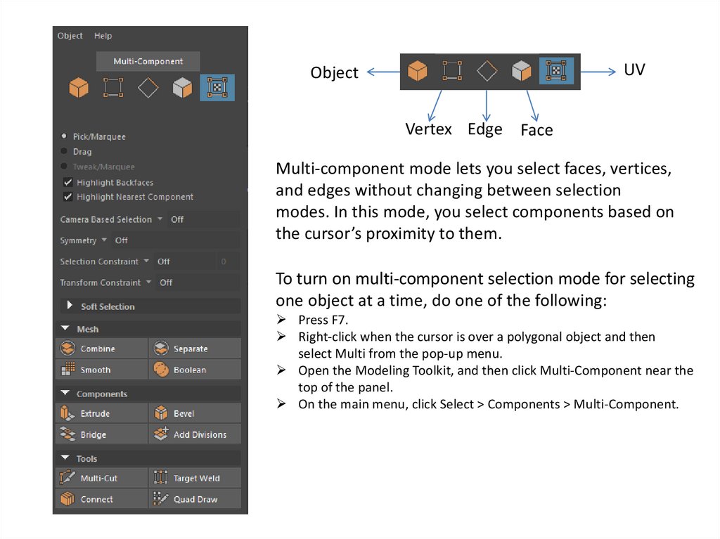
UVObject
Vertex Edge Face
Multi-component mode lets you select faces, vertices,
and edges without changing between selection
modes. In this mode, you select components based on
the cursor’s proximity to them.
To turn on multi-component selection mode for selecting
one object at a time, do one of the following:
Press F7.
Right-click when the cursor is over a polygonal object and then
select Multi from the pop-up menu.
Open the Modeling Toolkit, and then click Multi-Component near the
top of the panel.
On the main menu, click Select > Components > Multi-Component.
3.
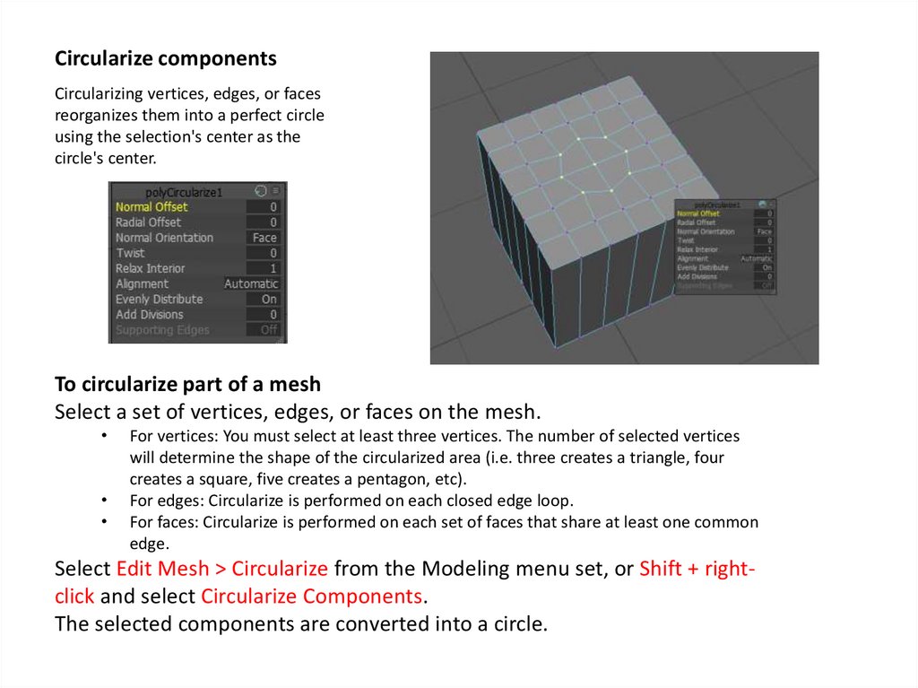
Circularize componentsCircularizing vertices, edges, or faces
reorganizes them into a perfect circle
using the selection's center as the
circle's center.
To circularize part of a mesh
Select a set of vertices, edges, or faces on the mesh.
For vertices: You must select at least three vertices. The number of selected vertices
will determine the shape of the circularized area (i.e. three creates a triangle, four
creates a square, five creates a pentagon, etc).
For edges: Circularize is performed on each closed edge loop.
For faces: Circularize is performed on each set of faces that share at least one common
edge.
Select Edit Mesh > Circularize from the Modeling menu set, or Shift + rightclick and select Circularize Components.
The selected components are converted into a circle.
4.
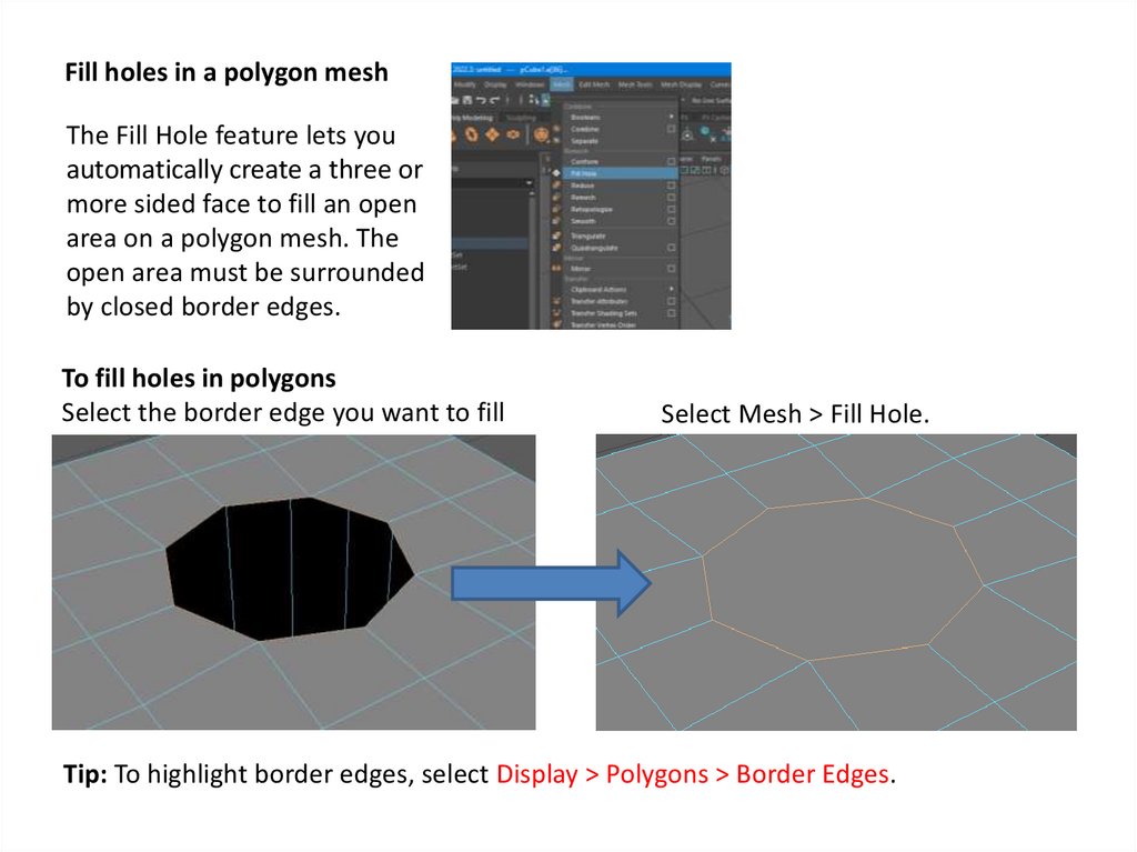
Fill holes in a polygon meshThe Fill Hole feature lets you
automatically create a three or
more sided face to fill an open
area on a polygon mesh. The
open area must be surrounded
by closed border edges.
To fill holes in polygons
Select the border edge you want to fill
Select Mesh > Fill Hole.
Tip: To highlight border edges, select Display > Polygons > Border Edges.
5.
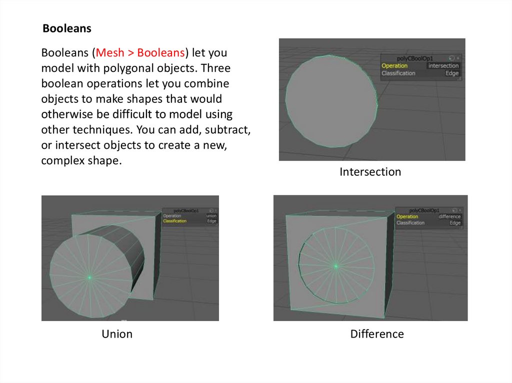
BooleansBooleans (Mesh > Booleans) let you
model with polygonal objects. Three
boolean operations let you combine
objects to make shapes that would
otherwise be difficult to model using
other techniques. You can add, subtract,
or intersect objects to create a new,
complex shape.
Union
Intersection
Difference
6.
Bridge CommandYou can construct faces between pairs of
border edges using the Bridge command. The
resulting bridged faces are merged into the
original mesh. Bridge is useful when you need
to connect two sets of edges together with a
piece of mesh.
Use one of the following methods to access
the Bridge command:
•Select Edit Mesh > Bridge in the main menu bar
•Select Bridge from the marking menu (Shift +
right-click)
•Click
in the Modeling Toolkit