

 Программное обеспечение
Похожие презентации:


Diagnostic tool introduction
1.
Diagnostic Tool IntroductionKeeway Aftersale Service Division
2012/11/01
2.
Index1.Diagnostic tool Appearance/Measurement
2.Features
3.Connection method
4.Function overview
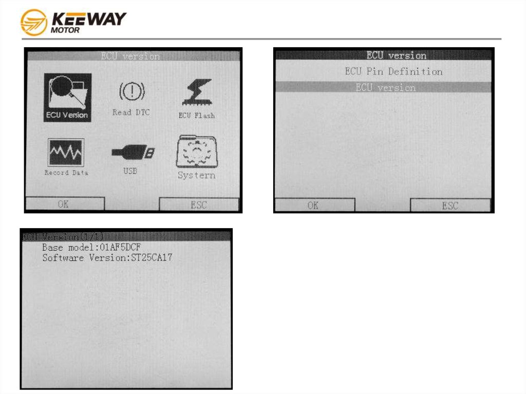
a) ECU version
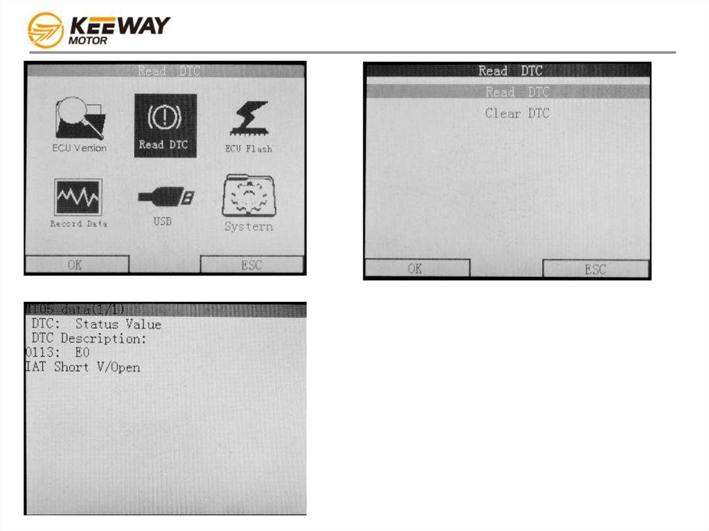
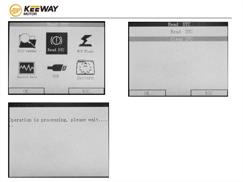
b) Read DTC
c) ECU flash
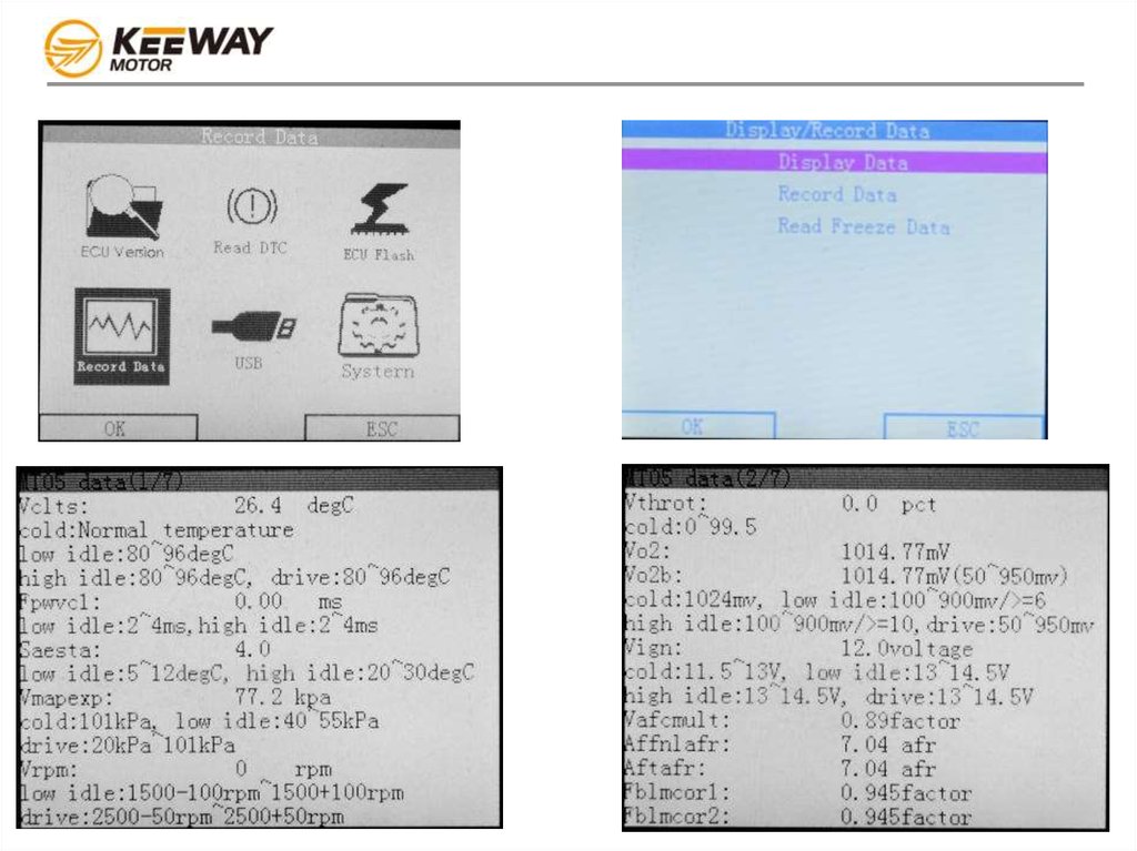
d) Record data
e) USB connection
f) System
3.
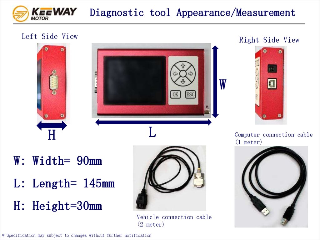
Diagnostic tool Appearance/MeasurementLeft Side View
Right Side View
W
H
L
W: Width= 90mm
L: Length= 145mm
H: Height=30mm
Vehicle connection cable
(2 meter)
* Specification may subject to changes without further notification
Computer connection cable
(1 meter)
4.
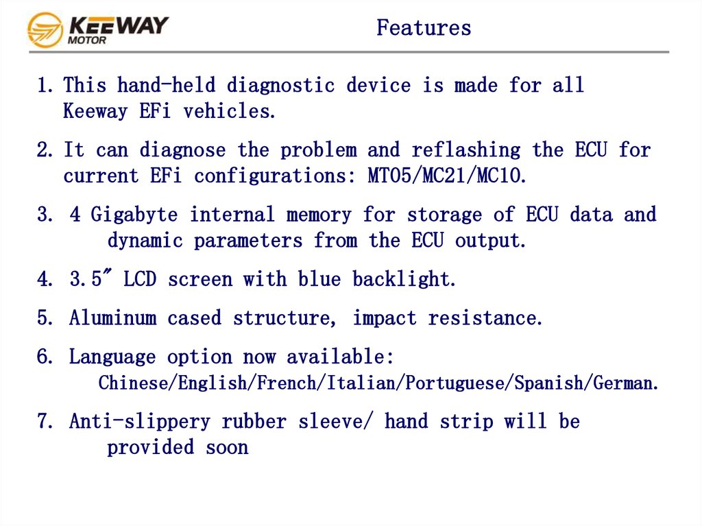
Features1. This hand-held diagnostic device is made for all
Keeway EFi vehicles.
2. It can diagnose the problem and reflashing the ECU for
current EFi configurations: MT05/MC21/MC10.
3. 4 Gigabyte internal memory for storage of ECU data and
dynamic parameters from the ECU output.
4. 3.5" LCD screen with blue backlight.
5. Aluminum cased structure, impact resistance.
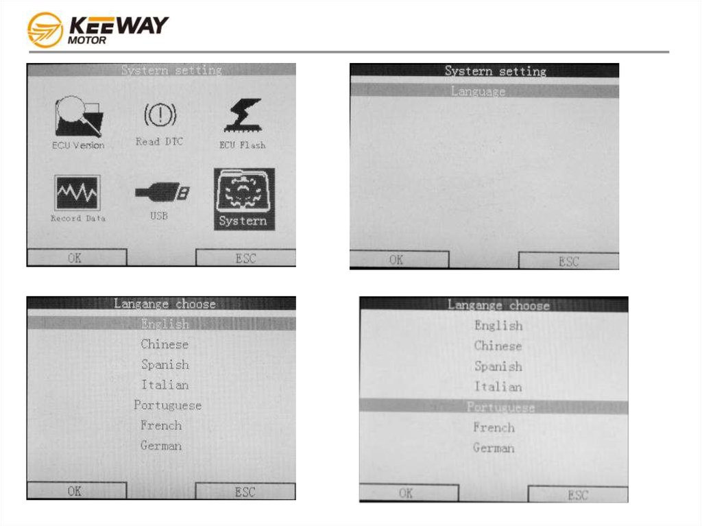
6. Language option now available:
Chinese/English/French/Italian/Portuguese/Spanish/German.
7. Anti-slippery rubber sleeve/ hand strip will be
provided soon
5.
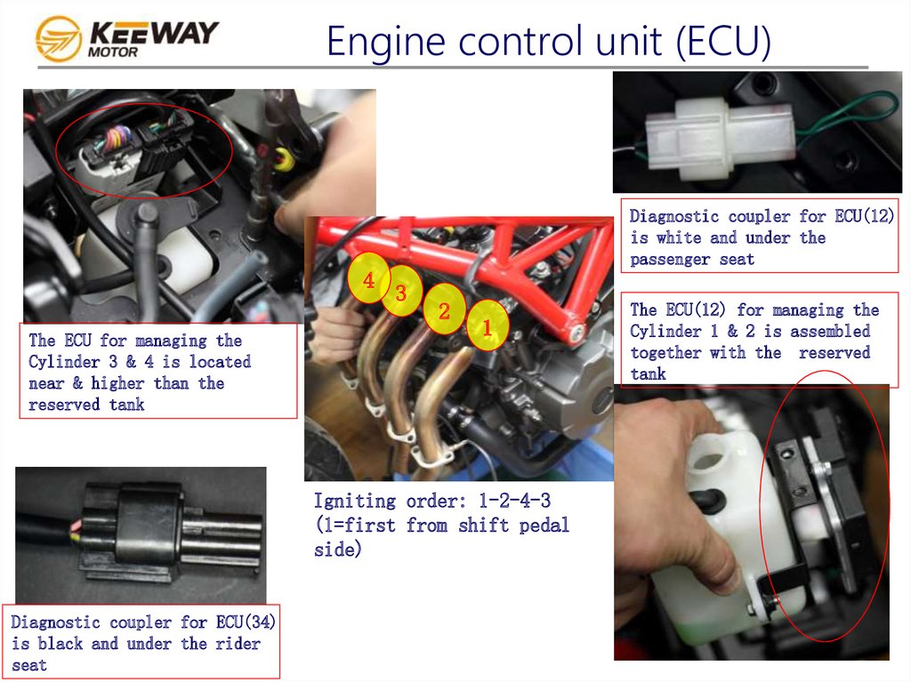
Engine control unit (ECU)Diagnostic coupler for ECU(12)
is white and under the
passenger seat
4
The ECU for managing the
Cylinder 3 & 4 is located
near & higher than the
reserved tank
3
2
1
Igniting order: 1-2-4-3
(1=first from shift pedal
side)
Diagnostic coupler for ECU(34)
is black and under the rider
seat
The ECU(12) for managing the
Cylinder 1 & 2 is assembled
together with the reserved
tank
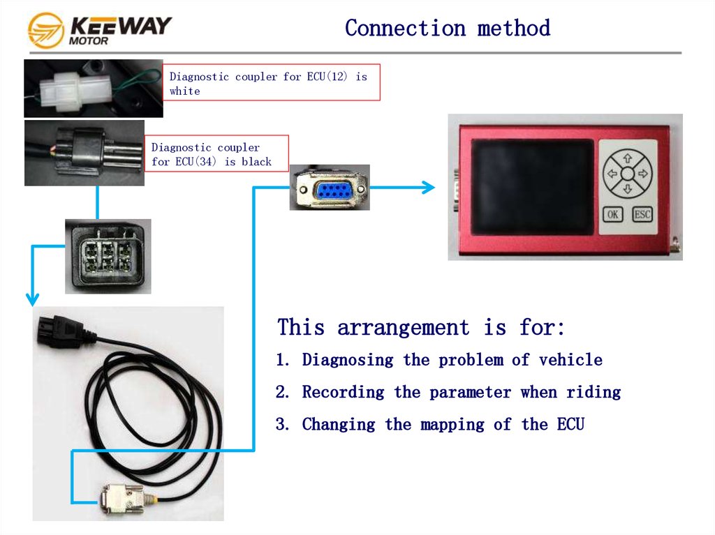
6.
Connection methodDiagnostic coupler for ECU(12) is
white
Diagnostic coupler
for ECU(34) is black
This arrangement is for:
1. Diagnosing the problem of vehicle
2. Recording the parameter when riding
3. Changing the mapping of the ECU
7.
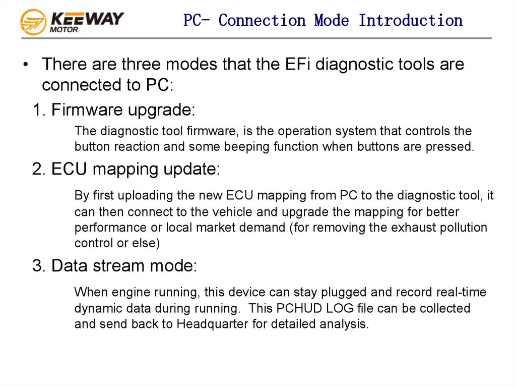
PC- Connection Mode Introduction• There are three modes that the EFi diagnostic tools are
connected to PC:
1. Firmware upgrade:
The diagnostic tool firmware, is the operation system that controls the
button reaction and some beeping function when buttons are pressed.
2. ECU mapping update:
By first uploading the new ECU mapping from PC to the diagnostic tool, it
can then connect to the vehicle and upgrade the mapping for better
performance or local market demand (for removing the exhaust pollution
control or else)
3. Data stream mode:
When engine running, this device can stay plugged and record real-time
dynamic data during running. This PCHUD LOG file can be collected
and send back to Headquarter for detailed analysis.
8.
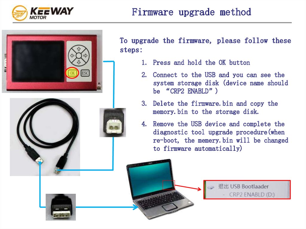
Firmware upgrade methodTo upgrade the firmware, please follow these
steps:
1. Press and hold the OK button
2. Connect to the USB and you can see the
system storage disk (device name should
be “CRP2 ENABLD”)
3. Delete the firmware.bin and copy the
memory.bin to the storage disk.
4. Remove the USB device and complete the
diagnostic tool upgrade procedure(when
re-boot, the memery.bin will be changed
to firmware automatically)
9.
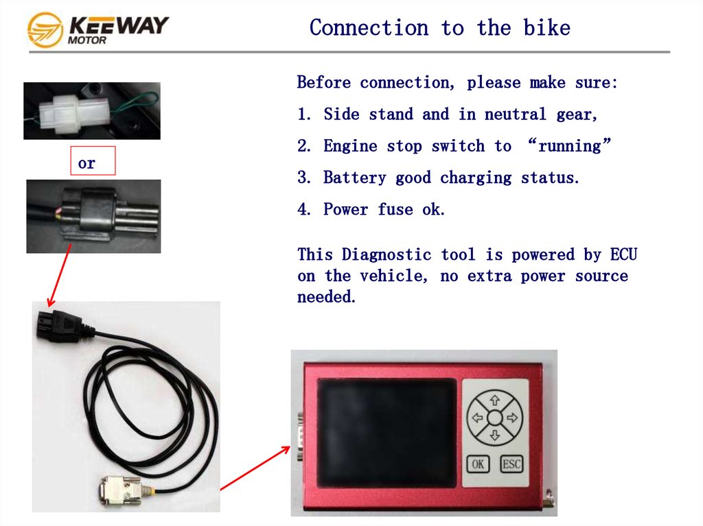
Connection to the bikeBefore connection, please make sure:
1. Side stand and in neutral gear,
or
2. Engine stop switch to “running”
3. Battery good charging status.
4. Power fuse ok.
This Diagnostic tool is powered by ECU
on the vehicle, no extra power source
needed.
10.
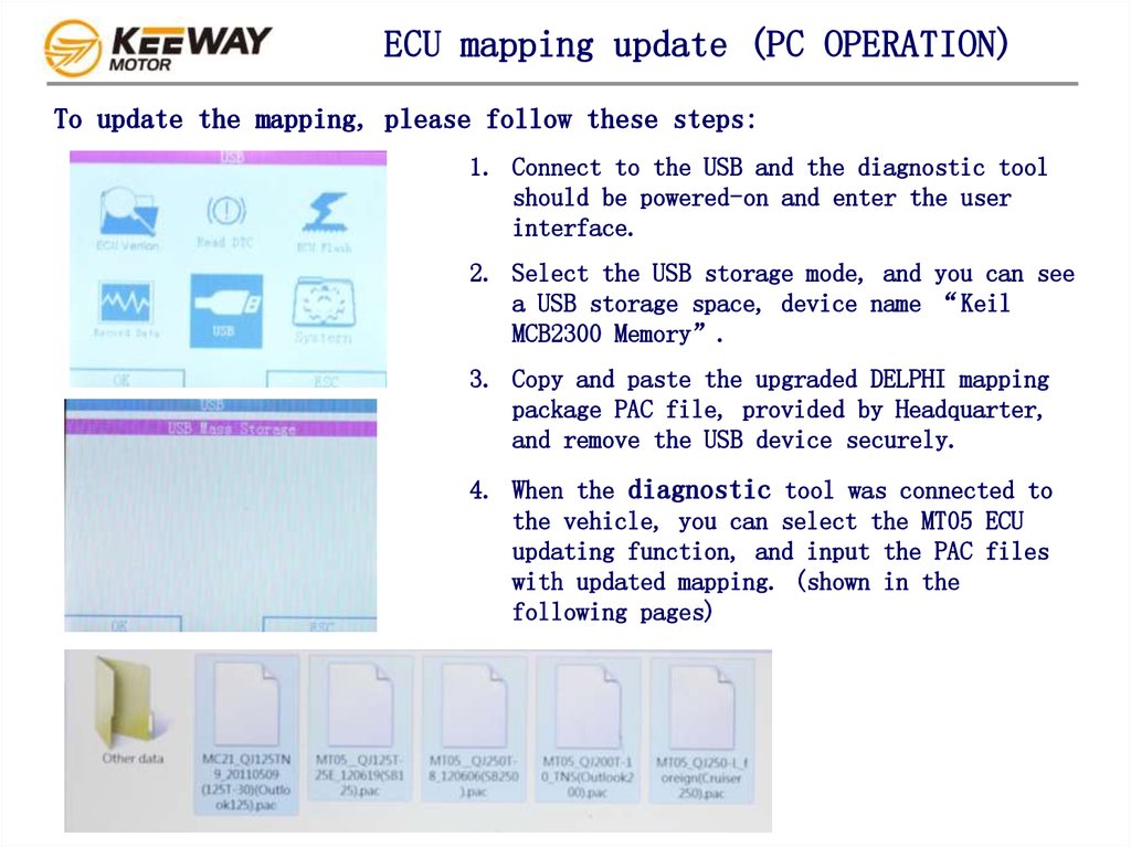
ECU mapping update (PC OPERATION)To update the mapping, please follow these steps:
1. Connect to the USB and the diagnostic tool
should be powered-on and enter the user
interface.
2. Select the USB storage mode, and you can see
a USB storage space, device name “Keil
MCB2300 Memory”.
3. Copy and paste the upgraded DELPHI mapping
package PAC file, provided by Headquarter,
and remove the USB device securely.
4. When the diagnostic tool was connected to
the vehicle, you can select the MT05 ECU
updating function, and input the PAC files
with updated mapping. (shown in the
following pages)
11.
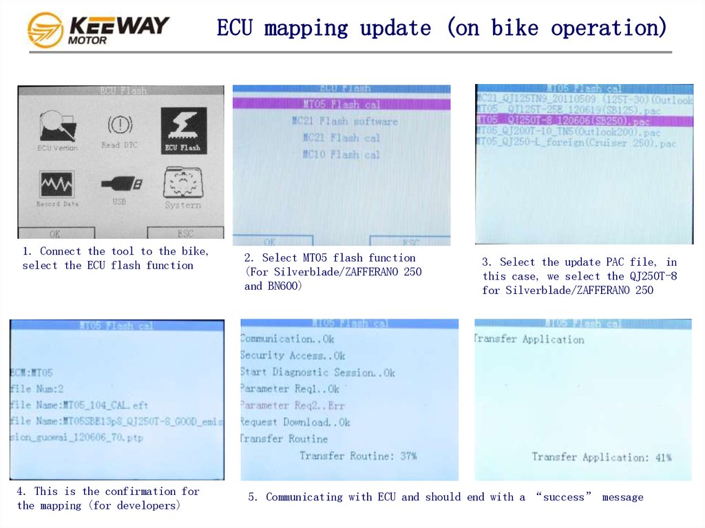
ECU mapping update (on bike operation)1. Connect the tool to the bike,
select the ECU flash function
4. This is the confirmation for
the mapping (for developers)
2. Select MT05 flash function
(For Silverblade/ZAFFERANO 250
and BN600)
3. Select the update PAC file, in
this case, we select the QJ250T-8
for Silverblade/ZAFFERANO 250
5. Communicating with ECU and should end with a “success” message
12.
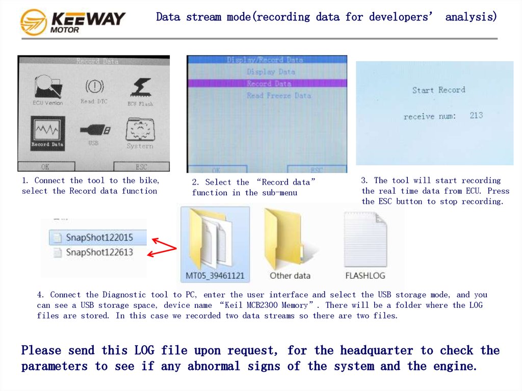
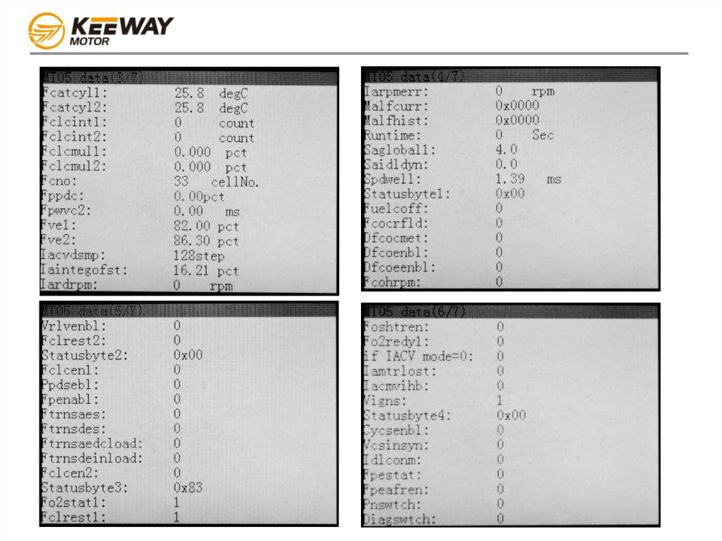
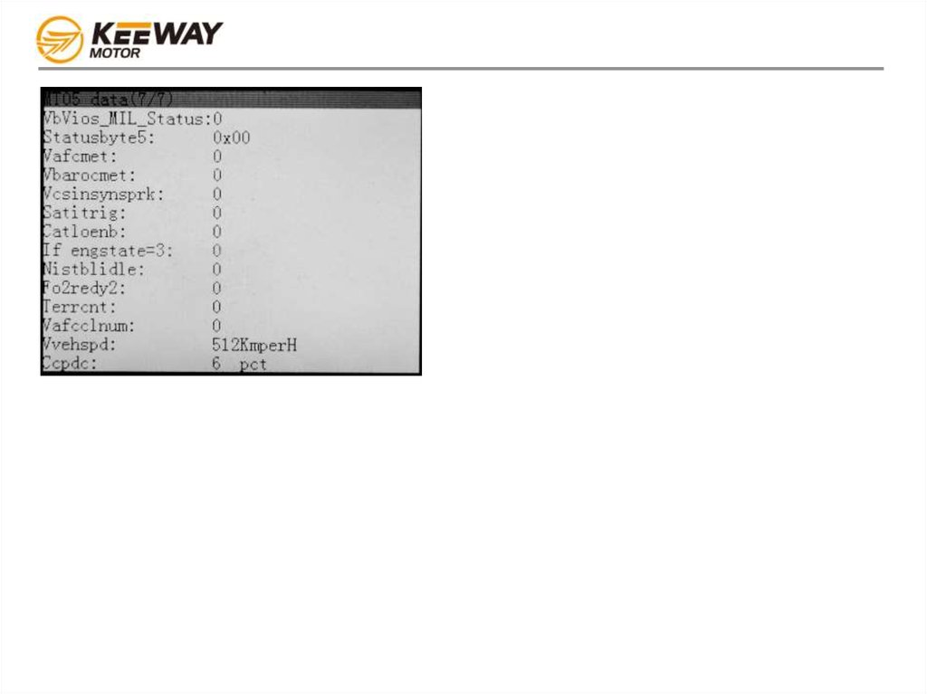
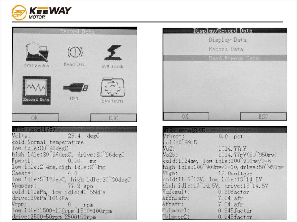
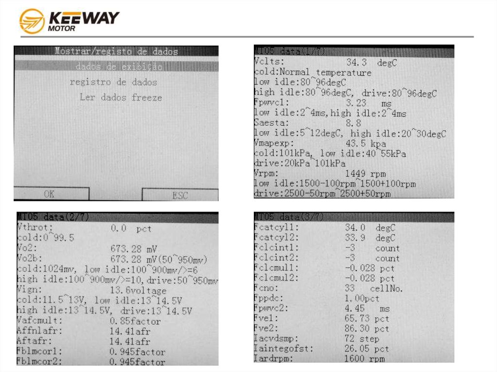
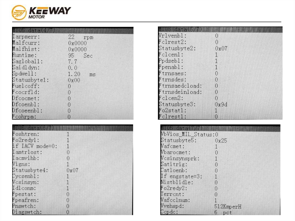
Data stream mode(recording data for developers’ analysis)1. Connect the tool to the bike,
select the Record data function
2. Select the “Record data”
function in the sub-menu
3. The tool will start recording
the real time data from ECU. Press
the ESC button to stop recording.
4. Connect the Diagnostic tool to PC, enter the user interface and select the USB storage mode, and you
can see a USB storage space, device name “Keil MCB2300 Memory”. There will be a folder where the LOG
files are stored. In this case we recorded two data streams so there are two files.
Please send this LOG file upon request, for the headquarter to check the
parameters to see if any abnormal signs of the system and the engine.